Scatter radiation considerably affects radiographic image quality by reducing image contrast and contributing to a non-uniform background. Images containing a large portion of scatter radiation may result in an incorrect diagnosis. In the past few years, many efforts have been made to reduce the effects of scatter radiation on radiographic images. The purpose of this study is to accurately measure scatter fractions and evaluate the effectiveness of beam-stop arrays. To measure scatter fraction accurately, a beam-stop array and the SFC (Scatter Fraction Calculator) program were developed. Images were obtained using the beam-stop array for both an anti-scatter technique with an anti-scatter grid and an air gap technique. The scatter fractions of the images were measured using the SFC program. Scatter fractions obtained with an anti-scatter grid were evaluated and compared to scatter fractions obtained without an anti-scatter grid. Scatter fractions were also quantitatively measured and evaluated with an air gap technique. The effectiveness of the beam-stop array was demonstrated by quantifying scatter fractions under various conditions. The results showed that a beam-stop array and the SFC program can be used to accurately measure scatter fractions in radiographic images and can be applied for both developing scatter correction methods as well as systems.
Key Words: Scatter fraction, Beam-stop array, SFC program
This research sponsored by the Development Center of Mobile Emer- gency Medical Information System, Ministry of Health and Welfare (02-PJ3-PG6-EV08-0001).
Submitted November 3, 2009, Accepted December 17, 2009 Corresponding Author: Hee-Joung Kim, Department of Radiological Science, Institute of Health Science, Yonsei University, 234, Maeji-ri, Heungeop-myeon, Wonju 220-710, Korea
Tel: 033)760-2963, Fax: 033)760-2562 E-mail: [email protected]
INTRODUCTION
As an X-ray beam passes through a substance, five types of interactions can occur, including Compton effect, photoelectric effect, Raleigh scattering, pair production, and nuclear photoeffect. The Compton effect and Raleigh scattering result in the emission of scatter radiation, which causes many prob- lems in radiography.
1,2)Scatter radiation can account for more than 90% of X-ray flux detected in the mediastinum region of chest radiographs and more than 70% on lung radiographs ac- quired without an anti-scatter grid.
3)This scatter radiation con- tributes to reducing contrast and causes image fog in clinical
radiographs. Because of these harmful effects of scatter radia- tion, it is important to find techniques for its reduction.
4)As a first step toward reducing scatter, one should carefully compress the object to be imaged and use tight collimation.
However, especially in clinical situations, additional techniques
for scatter reduction are still necessary. These may include the
use of an anti-scatter grid, an air gap technique, or a slot tech-
nique,
2)the first two of which are the most common techni-
ques for reducing scatter. The anti-scatter grid consists of a
periodic array of radio-opaque foil strips (usually lead), sepa-
rated by strips of radiolucent spacing material (typically paper
or aluminum).
5)It can transmit the primary radiation, and also
block scatter x-rays from all directions.
5)The air gap technique
is based on the application of a certain distance, between the
patient and the image recording system.
2)The reduction of the
scatter at the image receptor with increasing distance from the
patient’s body has been described by various authors.
6)To improve image quality and reduce radiation exposure by
reducing scatter radiation, we must accurately measure the
scatter fraction, which is defined as the ratio of the intensity
Fig. 1. (a) The photography of the
beam-stop array. (b) Schematic diagram of the beam-stop array.Fig. 2. Schematic diagram of photon trajectories for the
beam-stop scatter measurement.of the scatter radiation to that of the total radiation. Accurate evaluation of the scatter fraction requires an accurate estima- tion technique. We used a beam-stop array technique, which allows for scatter fraction measurements over various anatomic regions on radiographic images.
The goals of this study were to measure scatter fractions by developing an SFC (Scatter Fraction Calculator) program and to evaluate the effectiveness of the beam-stop array technique.
MATERIALS AND METHODS
1. Beam-stop array and FDA phantom
Scatter radiation measurements of a digital radiographic sys- tem were evaluated in terms of scatter fractions by using a beam-stop array and a geometric phantom.
To measure the scatter fractions, a beam-stop array was manufactured. The beam-stop array was constructed by 224 lead cylinders used as beam stops and 41.7×47.3 cm acrylic sheet. Each beam stop consisted of a 3 mm diameter and 6 mm height embedded in a 6 mm thickness sheet of acrylic.
The intervals between the edges of each lead cylinder were 25 mm (Fig. 1).
The thickness (which represents more than 20 half-value layers: a transmission of 10
−6at diagnostic X-ray energies) of the beam-stop array effectively blocked all primary X-ray beams (Fig. 2).
4,7)The phantom was manufactured based on a design by the Food and Drug Administration (FDA) for use in the Nation- wide Evaluation of X-ray Trends (NEXT) program (Fig. 3a).
This FDA phantom, representing the chest of an average sized adult patient, was designed to assess the effects of at-
tenuation and scatter characteristics. The phantom includes blocks of acrylic, Lucite and aluminum. The geometry of the FDA phantom is shown in Fig. 3b.
8,9)2. Imaging system
Images were acquired using a digital radiographic system.
Table 1 lists the physical specifications of the imaging system.
3. Geometry and image acquisition
The distances from focus to detector and object were 180 cm and 153.3 cm, respectively. The beam-stop array was placed in front of the FDA phantom (Fig. 4, 5).
The uses of an anti-scatter grid and an air gap technique
have been the most common techniques for reducing scatter
radiation. The scatter fractions were measured using both of
these techniques.
Fig. 3. (a) The manufactured FDA
chest phantom. (b) Schematic dia- gram of the FDA phantom in side view. Al indicates aluminum.Table 1. The physical specifications of the imaging system.
Characteristic Value
Imaging system TOSHIBA E7239X generator with a DRTECH FDXD-1417 detector Capture element Flat panel detector (direct conversion)
TFT- amorphous selenium Detecting area 356×427 mm
Image matrix size 2,560×3,072 Dynamic range 16,000:1 Image pixel size 0.139×0.139 mm
Filtration 1.8 mm Al
Focal spot size 2.0/1.0 mm
1) Measurement of scatter fractions with and without an anti-scatter grid: We measured scatter fractions both with and without an anti-scatter grid.
8,9)Exposures were made at 80 kV and 120 kV for an average sized adult chest. Fixed exposure factors were 320 mA, 0.01 sec exposure time and a distance of 180 cm from focus to detector. The anti-scatter grid had a density of 215 lines/inch and a ratio of 8:1 (Jungwon Precision Ind. Co., Ltd, South Korea).
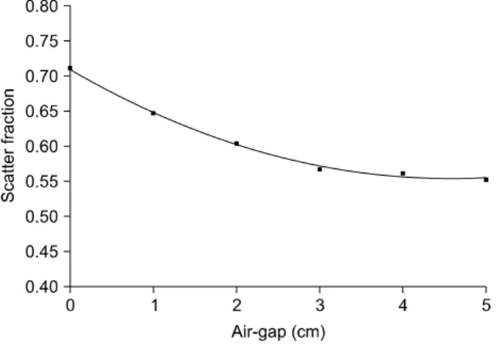
2) Measurement of scatter fractions using an air gap technique: We measured the scatter fraction by increasing the air gap (increased from 0 to 5 cm with 1 cm spacing) without using an anti-scatter grid. Exposures were made at 80 kV, 320 mA and 0.01 sec exposure time. Fig. 5 shows the ge- ometry for the scatter fraction measurement made by increas- ing the air gap.
4. Data analysis
A total of ten images were acquired in digital radiography.
We used 16 bits to represent the intensity values of the image, making it possible to register 65,536 different gray levels.
Images were obtained using a beam-stop array for both the an- ti-scatter grid and air gap techniques.
The scatter fraction is defined as the ratio of the intensity of scatter radiation to total radiation
7):
To calculate the scatter fraction, an SFC program was devel- oped using MATLAB. The SFC program allowed extraction of mean ROI values behind the beam-stop shadow (the “scatter”
value) and extracted the mean ROI values in between the beam-stops (“total” or “nonscatter+scatter” radiation). To re- duce the error of mean ROI values, the region of interest (15×15 pixels) was set to exclude the pixels bordering the beam-stop edges.
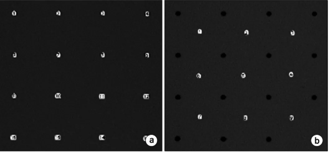
7)Fig. 6 illustrates the ROI (15×15 pixels) behind the beam stop shadow in the radiographic images.
The mean value of scatter radiations at the range of 16
beam-stop arrays and total radiations at the range of 9 ROI
(15×15 pixels) values were calculated (Fig. 7). This number of
beam-stops was adequate to characterize the scatter frac-
tion.
10-13)The blue circles on the Fig. 7 show the ROIs for
measurement of mean gray value.
Fig. 4. Schematic diagram of the
anti-scatter grid technique.Fig. 5. Schematic diagram of the
air-gap technique. The air-gap was increased from 0 to 5 cm with 1 cm spacing by moving the de- tector.Fig. 6. ROI (15×15 pixels) behind the beam stop shadow. The
area of a rectangular indicates the ROI for measurement of mean gray value.For each beam-stop array image, the scatter fraction was then measured using the SFC program.
RESULTS
1. Measurement of scatter fractions with and without an anti-scatter grid
At 80 kVp and 120 kVp, the differences between the scatter fractions with and without the anti-scatter grid are show in Table 2 and 3, respectively.
With the anti-scatter grid, scatter fractions were approx- imately 0.55 and 0.55 at 80 kVp and 120 kVp, respectively.
Without the anti-scatter grid, the scatter fractions were approx- imately 0.71 and 0.71 at 80 kVp and 120 kVp, respectively.
The reference and experimental data at 80 kV and 120 kV without the anti-scatter grid were compared.
2)Fig. 8 shows a similarity between the reference and ex-
Fig. 7. (a) ROIs behind the beam
stop (for the scatter value), (b) ROIs in between beam stops (for the "total," or "nonscatter+scatter,"value).
Table 2. Scatter fractions with and without an anti-scatter grid at 80 kVp.
Scatter radiation Total radiation Scatter fraction Mean pixel value of the ROI (m±SD)
With 188±3.13 344±16.53 0.55
Without 582.7±22.55 815.6±31.45 0.71
Table 3. Scatter fractions with and without an anti-scatter grid at 120 kVp.
Scatter radiation Total radiation Scatter fraction Mean pixel value of the ROI (m±SD)
With 367±4.69 667±5.84 0.55
Without 1,053±32.32 1,484±46.89 0.71
Fig. 8. Comparison of the reference data
2) with the experimental data.Table 4. Scatter fractions using the air gap technique.
Air-gap (cm)
Scatter radiation Total radiation Scatter fraction Mean pixel value of the ROI (m±SD)
0 579.0±11.23 815.6±8.78 0.71
1 524.7±17.32 812.4±13.01 0.65
2 470.4±26.33 780.8±33.87 0.60
3 432.6±12.95 764.2±31.60 0.57
4 419.0±7.97 748.0±4.65 0.56
5 400.4±16.98 725.2±28.55 0.55
perimental data. The scatter fraction depends on the X-ray tube voltage adapted from Reiss and Steinle 1973.
2)2. Measurement of scatter fractions using an air gap technique
Scatter fractions were measured using an air-gap technique in order to assess the usefulness of the beam-stop array and SFC program. Scatter fractions using the air-gap technique are shown in Table 4.
As for the beam-stop array technique, scatter fractions de- creased as the air-gap distance between the phantom and the detector increases. This effect is shown in Fig. 9.
DISCUSSION AND CONCLUSION
In this study, the effectiveness of the beam-stop array tech-
nique and SFC program in measuring and evaluating the scat-
ter effect in radiographic images was demonstrated. Scatter
fractions measured using the beam-stop array and SFC pro-
Fig. 9. Scatter fractions as a function of air gap size.
gram were in good agreement with previously reported values.
2)Scatter fractions are lower with the anti-scatter grid than without grid as shown in Table 2 and 3. Anti-scatter grids were able to reduce the scatter fraction to about 0.15 times.
The scatter fraction with a 5 cm air-gap was approximately 0.16 times lower than the scatter fraction with a 0 cm air-gap, which suggests that air-gap techniques are useful for scatter reduction.
The beam-stop array technique together with the SFC pro- gram may help in the study of scatter characteristics in radio- graphic images. To get a reasonable signal on the detector, a suitable patient dose would be required and the system needs to be optimized.
2)Based on these results, measured scatter ra- diation and total radiation were lower at 80 kVp than at 120 kVp. In previous studies, a low kilovoltage was recommended for chest imaging with CR. This is consistent with clinical practices in the United Kingdom.
8)In order to demonstrate that 80 kVp without an anti-scatter grid gives suitable exposure,
8)scatter fractions need to be measured with varying mAs.
Quantifying the exact scatter fraction may contribute to en- hance the image quality and to develop both scatter correction
45-56 (2003)
3. Samei E, Lo JY, Yoshizizymi TT, et al: Comparative scat- ter and dose performance of slot-scan and full-field digital chest radiography Systems. Radiology 235:940-949 (2005)
4. Floyd CE, Baker JA, Lo JY, Ravin CE: Posterior beam- stop method for scatter fraction measurement in digital radio- graphy. Investigate Radiology 27:119-123 (1992)
5. Tang CM, Stier E, Fischer K, Guckel H: Anti-scattering X-ray grid. Microsystem Technologies 4:187-192 (1998) 6. Sorenson JA, Floach J: Scatter rejection by air-gaps: an
empirical model. Medical Physics 1:308-316 (1985)
7. Floyd CE, Lo JY, Chotas HG, Ravin CE: Quantitative scatter measurement in digital radiography using a photo- stimulable phosphor imaging system. Medical Physics 18:
408-413 (1991)
8. Ertan F, Mackenzie A, Urbanczyk HJ, Ranger NT, Samei E: Use of effective detective quantum efficiency to opti- mize radiographic exposures for chest imaging with computed radiography. The International Society for Optical Engineering, Bellingham, 2009, pp. 153-163
9. Samei E, Ranger NT, MacKenzie AM, et al: Detector or system? Extending the concept of detective quantum efficiency to characterize the performance of digital radiographic imaging systems. Radiology 249:926-937 (2008)
10. Chotas HG, Van Metter RL, Johnson GA, Ravin CE:
Small object contrast in AMBER and conventional chest radiography. Radiology 180:853-859 (1991)
11. Jordan LK, Floyd CE, Lo JY, Ravinl CE: Measurement of scatter fractions in erect posteroanterior and lateral chest radiography. Radiology 188:215-218 (1993)
12. Baydush AH, Ghem WC, Floyd CE: Anthropomorphic ver- sus geometric chest phantoms: a comparison of scatter properties. Medical Physics 27:894-897 (2000)
13. Samei E, Saunders RS, Lo JY, et al: Fundamental imag- ing characteristics of a slot-scan digital chest radiographic system. Medical Physics 31:2687-2698 (2004)