A Study on Heat and Mass Transfer with the Different Flows in a Solar Desiccant Cooling System
Eflita, Yohana* Choi, Kwang-Hwan**
*Graduate school, Dept. of Refrigeration and Air Conditioning Engineering, Pukyong National University
**Dept. of Refrigeration and Air Conditioning Engineering, College of Mechanical Engineering, Pukyong National University
태양열제습냉방시스템에서의 유량에 따른 열전달 및 물질전달에 관한 연구
에프리타 요한나*, 최광환**
*부경대학교 냉동공조공학과 대학원
**부경대학교 공과대학 냉동공조공학과([email protected])
요약문
태양열 제습냉방은 액체흡수제를 이용한 냉각효과로 기존의 전기에너지를 가능케 하는 해결책 중 하나이다. 따라서 태양열을 거의 활용하지 않는 여름에 가열온수를 열원으로 활용하여 쾌적조건을 구현하는 본 연구의 대상인 태양열냉 방시스템은 제습기와 재생기로 크게 이루어져 있다. 본 논문은 제습기의 유량 변화에 따른 열전달 및 물질전달의 변 화를 실험과 이론적 해석으로 규명하고 있는데, 흐름의 양상은 병렬형과 대향류형을 대상으로 하고 있다.
실험결과와 이론해석이 비교적 잘 일치하였으며, 대향류형이 병렬형보다도 물질전달 면에서 유리하게 나타났으며, 입·출구의 엔탈피 차이에서도 크서 열전달에서도 우수한 것으로 나타났다. 또한 그 차이를 본 논문에서는 나타내었으 며, 일정한 높이나 길이 이상에서는 항상 일정함을 알 수 있었다. 따라서 본 논문의 결과들은 제습기의 유동흐름을 통 한 태양열냉방시스템 중 제습기의 설계 및 성능 향상에 도움을 줄 것이다.
Keywords: Dehumidifier(제습기), Heat transfer(열전달), Mass transfer(믈질전달), Lithium chloride(염화리튬), Packed tower(충진층)
Nomenclature
Ts = saturated temperature of moist air, oF(oC)
= relative humidity (%)
= Humidity ratio of saturated moist air
= mole fraction of water vapor
= water vapor in a saturated moist air sample
= specific enthalpy of dry air
= specific enthalpy of water vapor [논문] 한국태양에너지학회 논문집
Journal of the Korean Solar Energy Society
Vol. 30, No. 5, 2010 IS S N 1 5 9 8 - 6 4 1 1
투고일자 : 2010년 6월 3일, 심사일자 : 2010년 6월 20일, 게재확정일자 : 2010년 10월 15일 교신저자 : 최광환([email protected])
1. Introduction
One of the critical issues in this world is a energy crisis. Saving energy, especially electrical energy, is the one of solutions to solve the energy crisis. In summer, electrical energy tends to be consumed at very high rate. Electricity is used for operating conventional air conditioning system in order to create human comfort zone. The damp air (hot temperature and high humidity) can bring up uncomfortable condition to the occupants.
Many researchers had tested experimentally the performance of packed bed dehumidifier and regenerator [1 - 3]. Liquid desiccant air conditioning system [2 - 5] has been proposed as an alternative to replace conventional vapor compression cooling system in the hot and humid area. The packed tower is the most significant component to advance heat and mass transfer in the dehumidifier. Moisture is transferred from unconditioned air to the desiccant.
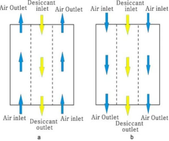
Figure 1. Flowing types counter flow type (a) and parallel flow type (b) in the packed tower
The outlet air temperature or humidity ratio may exceed the range of the inlet air when there is an inverse situation between both side parameters. Because of the interaction in heat and mass transfer process, the inlet air and inlet desiccant condition can generate this inverse. Hence knowing reachable outlet condition will greatly contribute to the design and optimization of a solar liquid desiccant system.
Previous experiments had been focused on the counter flow [2–5] or the cross flow patterns [6]. Almost no reported experiment has been performed on parallel flow type. In a sensible heat exchange, the counter flow configuration outperformed, and the parallel flow configuration performs lower than that of the counter flow type at the same conditions.
Several significant effects to the heat and mass transfer are decided by controlling variables. They are inlet air temperature, air humidity, air flow rate from the air side and desiccant temperature, concentration and liquid flow rate. This paper describes combined conditions which should be considered to get optimal mass transfer with working region. Working region is a range of temperature and humidity of inlet air condition, where mass transfer still exists between humid air and thick liquid desiccant. By using working region diagram, design for the optimal packed tower capacity can be performed to get greater heat and mass transfer effect consuming low electrical energy. It will also contribute to design of the packed tower and optimization of a solar liquid desiccant cooling system.
2. Experiment set-up and apparatus A solar liquid desiccant air‐conditioning system has been proposed as an alternative to replace conventional vapor compression cooling system for controlling air humidity.
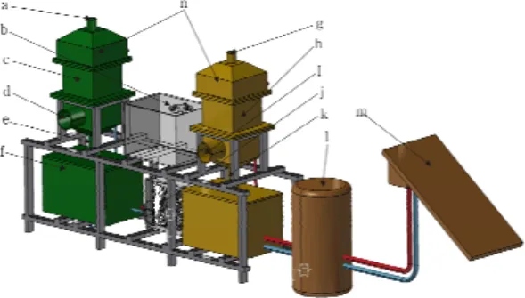
In this experiment, lithium chloride is used as the desiccant. Fig. 2 shows a schematic diagram of the solar desiccant cooling system, with a three dimensional view, suggested by Choi, et al[6].
Figure 2. Three dimensional view of a solar desiccant cooling system
Where is,
a. Air inlet of a parallel flow type or air outlet of a counter flow type in dehumidifier b. Transferring storage tank
c. Packed tower in dehumidifier
d. air outlet of a parallel flow type or air inlet of a counter flow type in dehumidifier e. Outlet of desiccant solution
f. Solution storage tank in dehumidifier g. Air inlet of a parallel flow type or air outlet
of a counter flow type in regenerator h. Packed tower in regenerator
i. Air outlet of a parallel flow type or air inlet of a counter flow type in regenerator j. Chiller
k. Inlet of solution
l. Thermal storage tank m. Solar collector
n. Solution distributing tank
The experiment procedures of the dehumidifier in both types are as the following:
Lithium chloride (Licl) as a strong liquid desiccant tank is cooled by a chiller in the storage. Licl temperature was kept at 18oC uniformly by a chiller. A small pump located in between chiller and storage tank was supported to circulate 4 l/min of Licl solution. 15 liters of Licl solution in the storage tank only circulated during the experiment. This volume was relatively small, because of monitoring the changes within working range of Licl solution in short time. Also because of the acid property of Licl liquid desiccant, the experimental apparatus needs to be made of the non‐metallic to avoid corrosive problems.
So the packed layer was made of acrylic material and dimension holds 400mm in width, 400mm in length, and 400mm in height. The structure of packing material imbedded inside the packed layer keeps a uniform shape. A Licl sprayer was installed at the packed layer and Licl distribution from the storage tank to the sprayer was supported by a small pump. With gravity force, Licl solution dropped through the packed layer without depending on any additional energy and back to the storage tank.
To make the humid air contact with a liquid desiccant, a blower was adopted at outlet of the duct. The air speed was
supplied with 10 m/s circulating inside the room with no inducing the outside air.
In pattern of the parallel flow type, inlet position of the humid air is located at upper part of the packed layer and lower part of the packed layer with the counter flow.
Behavior of heat and mass transfer between humid air and Licl desiccant was monitored inside of the packed layer during the experiment.
In addition, the carryover of the desiccant at the terminal of the dehumidifier caused by much of air volume has been reduced by putting demister into the outlet of air.
3. Experiment instruments and method The apparatus was set up as described at the above and appropriate instruments were provided to measure the various values from the experiment.
Liquid desiccant flow rate was measured by Dewier placed before the sprayer, after pumped to the packed tower. Air flow rate was measured by a Tesco anemometer, a digital vane type, acquisitioning the velocity directly in meter per second.
Air temperature and humidity were recorded by TandD, digital thermo―
recorder, respectively which has accuracy by 0.1oC and 0.1% difference.
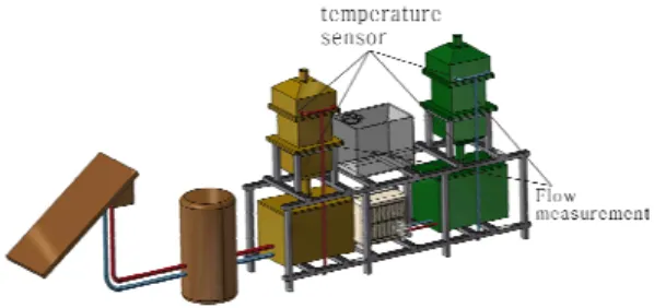
Specific gravity was measured by a hydrometer. The reading has been taken at several points as indicated in Fig. 3. All of the experiment data were acquired through Fluke Net Data Acquisition System (DAQ) with accuracy by 0.1oC difference after measured at inlet and outlet of the packed layer.
Figure 3. Instrument location in the dehumidifier experiment
4. Experiment analysis
When it comes to the calculation of heat and mass transfer in the packed tower, the air side gives more simple but accurate analysis than that of the liquid side. The humidity ratio, enthalpy, and moist volume of air can be calculated as follows.
Humidity ratio of the saturated moist air,
, on the psychometric chart, can also be founded by the following simpler polynomial.
The humidity ratio of the saturated air at the dry‐bulb temperature is obtained by the following equation:
Ws = a1+a2Ts+a3Ts2+a4Ts3+a5Ts4 (1) Where
a1 = 0.00080264 a3 = 2.542e-06 a2 = 0.014299 a4 =2.5855e-08 a5 = 4.038e-10
The saturated water vapor pressure of the air is determined by the following fraction:
=
(2)
The relative humidity of moist air, , is defined as the ratio of the mole fraction of the water vapor, , in a moist air to the mole fraction of the water vapor, , in a saturated moist air at the same temperature and pressure. The water vapor pressure of the air is calculated by the following equation.
= (3)
Then the humidity ratio of air would be as following:
(4)
The following assumptions are suggested for the enthalpy calculation of moist air:
1. The ideal gas equation and Gibbs‐
Dalton law are valid.
2. The enthalpy of dry air is equal to zero at 0oF(17.8oC).
3. All water vapor contained in the moist air is vaporized at 0oF(17.8oC).
4. The enthalpy of saturated water vapor at 0oF(17.8oC) is 1061 Btu/lb (2468 kJ/kg).
5. For convenience in calculation, the enthalpy of moist air is taken to be equal to the enthalpy of mixture of dry air and water vapor in which the amount of dry air is exactly equal to 1 lb (0.454 kg).
Based on the preceding assumptions, the enthalpyh of moist air can be calculated as follows:
(5)
Here, specific enthalpy of the dry air, , is given by following equation:
(6)
On the other hand, specific enthalpy of the water vapor, , at constant pressure can be approximated by the following:
(7)
Then enthalpy of the moist air can be evaluated as the following:
(8)
Here, by replacing measured values directly with symbols in the above equation, the equation can be transformed as equation (9):
(9)
In moist air, the dry air, water vapor and moist air is supposed to occupy the same volume. If the ideal gas equation can be applied, the moist volume of the air is transformed as follows:
(10)
Density of the moist air can be also obtained:
(11)
In addition, mass transfer between moist
air and liquid desiccant is given as follows:
(12)
5. Results and discussion
Contacting effect between air and liquid in the packed layer with two different flow patterns, counter flow pattern and parallel flow pattern, was evaluated from the measuring data. Performance on the solar desiccant cooling system was analyzed from the view of heat and mass transfer.
5.1 Counter flow type
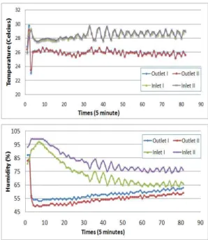
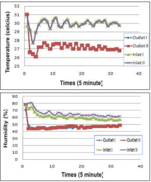
In the counter flow type experiment, air was circulated inside the room by a blower and the direction of liquid flow was reverse to the air. The variation on the humidity and temperature of air was shown in Fig. 4.
This result has shown that the humidity and temperature decrease in the room took place when this system was adopted practically.
In general, the comfortable relative humidity at 27℃ is about 60%. The result also shows that the air in the room reached the human comfort boundary at 270 seconds after strating the experiment with 15 liters of liquid desiccant.
It is significantly quick when considering the human comfort standard..
In the counter flow type, inlet and outlet solution temperature didn't show a large difference and also both air temperatures had same trend in Fig. 4. However, it had showed that humidity changes became constant in the reign of comfort 60%(R.H) after dehumidification.
Enthalpy difference between inlet and outlet had became less after losing the absorbing potential as time paseed by as shown in
Fig. 5, In addition, mass transfer rate also became smaller than that of the starting time.
Figure 4. Changes on air temperature (above) and humidity (below) in the counter flow type
Figure 5. Enthalpy (above) and mass transfer (below) in the counter flow type
5.2 P arallel flow type
In the parallel flow type, the blower suction direction was changed while it stayed the same in the counter flow type.
Fig. 6 shows the experiment result of temperature and humidity variation.
Figure 6. Changes on air temperature (above) and humidity (below) in the parallel flow type
In the parallel flow type, both inlet and outlet temperature of air and solution didn't show any changes. Also, humidity showed very slight difference starting, but didn't show any difference afterwards. Enthalpy difference between inlet and outlet also showed the same trend as humidity.
These results indicated that heat and mass transfer rate in the counter flow type are superior to the parallel flow type. As a result, compared to the counter flow type, enthalpy and mass transfer changing rates in the parallel flow type are lower than the
ones in the counter flow type.
Figure 7. Enthalpy and mass transfer in the parallel flow type
6. Conclusions
The experiments were performed based on the performance of dehumidifying ability with two different flowing types in a dehumidifier. This analysis was also performed from a point of dehumidifying capability and the conclusions are as follows;
(1) In the counter flow type, inlet and outlet solution temperature didn't show a large difference, but humidity changes became constant keeping stay in the reign of comfort zone within short time after dehumidification.
(2) Enthalpy difference in between inlet and outlet had became less after losing the absorbing potential and mass transfer
rate also became smaller than that of the starting time in the counter flow type.
(3) In the parallel flow type, humidity, temperature, enthalpy and mass transfer rate from both sides, inlet and outlet, had no significant difference compared to the ones in the counter flow type.
(4) These results indicated that the performance of heat and mass transfer in the counter flow type is superior to the parallel flow type by showing significant difference.
Acknowledgement
This work was supported by the Pukyong National University Research Fund in 2008(P3-2006-018) and we especially thank Mr. Sukmaji for this work.
7. References
1. Waugman D G, Kini A Kettleborough C F. A review of desiccant cooling system, J Enegy Resource Technology, Vol 8, 1993
2. Chung T W, Ghosh T K, Hines A L.
Comparison between random and structure packing for dehumidification, .IND Chem Res, 35(1), 1996
3. Patnik S, Lenz T G, Lof G O G.
Performers studies for an experiment solar open‐liquid desiccant air dehumidification system, Solar Energy, 123-135, vol 44(3), 1990
4. Li W Y, Dong Y, Fang C C. The experimental research of liquid dehumidifying system, Acta Energ Solaris Sinica, 2000[in Chinese]
5. Fumo N, Goswani D Y. Study of an aqueous lithium chloride desiccant system:
air dehumidification and desiccant regeneration, Solar Energy, 351-356, vol 72(4), 20002
6. Choi, K. H. et al., Development of solar/air conditioning system using hot water from solar collectors. Refrigeration and Air Conditioning Seminar, Pukyong National University, 70-78, 2004