Technical considerations for engineering of crane pedestal operated in North-Western Australia Offshore
7
0
0
전체 글
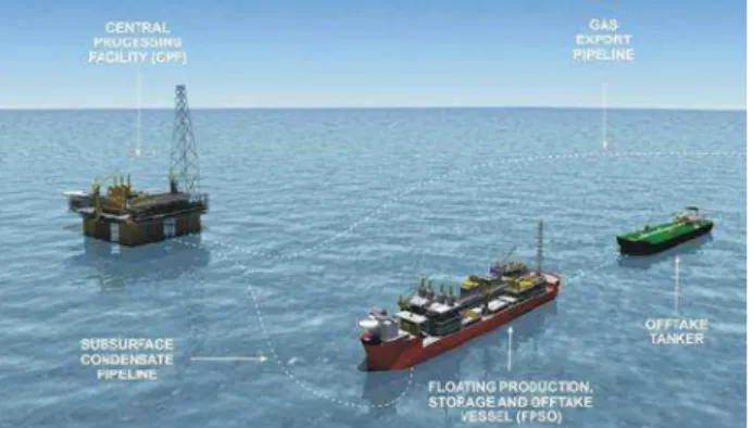
(2) 송준호・김용운・이경석・김만수. Gas from the Ichthys Field will undergo preliminary. The Hull appurtenances together with their foundations. processing at the offshore central processing facility (CPF). constitute “Offshore areas”. The remaining parts of the Hull. to remove water and raw liquids, including a large proportion. named "Ship areas".. of the condensate. This condensate will be pumped to a. Offshore areas inside the Hull will generally correspond. floating production, storage and offloading (FPSO) facility. to the reinforced zone. Typical sketch showing the principle. anchored nearby, from which it will be transferred to shuttle. of offshore Areas is attached hereafter in Fig. 3.. tankers by tandem offloading system for delivery to markets. These FPSO facilities include mercury removal from condensate, flash gas compression, MEG regeneration / reclamation and produced water treatment facilities.. Fig. 3 Typical Sketch for Offshore Area. Fig. 2. Offshore Facilities Layout. “Offshore areas” will be designed, built and controlled according to the CLASS Offshore Rules and Project General Specification.. The purpose of this project is to design, construct, assemble and test for the new built Ichthys FPSO, to be. FPSO Hull will be designed in accordance with CLASS offshore standard “DNV-OS-C102” for ship areas design,. used in the development of Ichthys field offshore Australia.. “DNV-OS-C101” for offshore areas design and overall FPSO design.. 1.2 Segregation Ship/Offshore Areas 1.3 Description of crane pedestal foundations Offshore areas designate all major appurtenances crane pedestal foundations fixed on the hull. A crane is a type of machine, generally equipped with a. structure, which are specific to FPSO and do not exist as such on ships. The offshore area includes its supports and. hoist, wire ropes or chains, and sheaves, that can be used both to lift and lower materials. It is mainly used for lifting. the corresponding hull reinforcements which are influenced. heavy things and transporting them to designated location.. by relevant loads. These areas carry significant loads through hull plating. As a general principle, supports for. This project uses the board and offshore cranes with maximum dynamic overturning moment 6000tm for crane. these interfaces shall be arranged in compliance with the. system, maximum lifting capacity of 75 tons and diesel. main framing of the hull structure. Sharp transitions between supports, reinforcements and the hull main structure shall. engine as prime mover for hydraulic system as shown in Fig. 4. A pedestal is located on the cargo deck. In FPSO, the. always be avoided. Qualified plates of through- thickness. crane is located at a higher position to avoid any. (Z-direction) shall be used on hull plating when required. Hull appurtenances designate all structural appendages. interference with topside module, etc. For this project, three (3) crane pedestal foundations are. connected to the Hull deck or more generally connected to. located in FWD, MID and AFT parts of FPSO and the design. the Hull structure which are specific to the FPSO Hull. The foundations of the Hull appurtenances are the structural. of its supporting structures is integrated with module support structures respectively.. including. reinforcements inside the FPSO Hull required to carry the. The crane pedestals shall be designed in accordance. forces and moments from the appurtenances and spread them into the FPSO structure.. with CLASS rules, requirements of Project specifications and API 2C shall also be fulfilled.. Special Issue of SNAK, September 2015. 35.
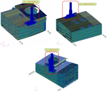
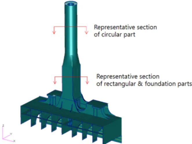
(3) North-Western Australia 해상에 운용되는 Offshore Crane Pedestal 설계. deflection because the pedestal structure is a cantilever beam and there is high value of crane reaction force relatively. From this circumstance, it needed to optimize the weight and control appropriate deflection. The configuration of pedestal structure obtained from the feasibility study is shown in Fig. 5.. Fig. 4 Configuration of Board and Offshore Crane There are two (2) design cases for which the cranes shall be designed; Crane operating and Crane Stowed.. Fig. 5 Configuration of Pedestal Structure. 2.2 Structural model extent and properties. The structures for crane pedestals and their supports are. The extent of crane pedestals has to be modeled to avoid. mainly categorized as special and first so the material selection and welding have to be carefully paid attention at. a boundary effect. The elements in FE model are properly. the detail design stage. The relative deflection between pedestal top and cargo deck shall be checked according to Project Specification. Deck structure shall be adequately reinforced for local buckling in way of the connection of pedestals and cargo deck, with thick insert plates and additional stiffening. The material either cargo deck plate or MSS top plate shall be considered with Z-grade material. The pedestals shall be designed with rectangle shape as. represented by shell, beam and rod elements and the mesh size is determined enough to represent the structural detail geometry. For the offshore area, the fine mesh is to be applied in general. And the very fine mesh is considered at high stressed areas. For the ship area, the longitudinal stiffener spacing mesh size is generally used and the fine mesh elements or very fine mesh elements are modeled if necessary. The hull scantling and FE analysis is based on net scantling approach. The structural evaluation is performed on the basis of the project net strength characteristic. The details are shown in Fig. 6.. high as possible to take some advantages of main traffic, deflection, etc. points of views and those are connected to the cylindrical shaped upper support with a smooth transition of conical pieces. The crane pedestal and associated hull internal reinforcements shall comply with the requirement of CLASS rules for offshore units and offshore standard API Spec 2C for Offshore Pedestal Mounted Cranes, whichever is the most stringent.. 2. Characteristics of Crane Pedestal 2.1 Feasibility study for configuration of pedestals For operation of crane, the pedestal structure has abt. 35 meters high for this unit. This characteristic causes excessive. 36. Fig. 6 Crane Pedestal FE Model. 대한조선학회 특별논문집 2015년 9월.
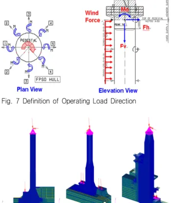
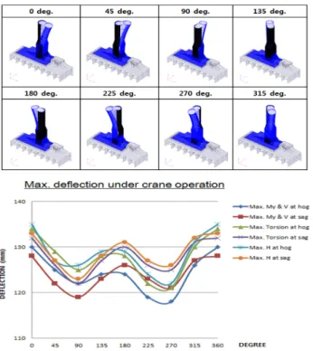
(4) 송준호・김용운・이경석・김만수. 3. Load Application 3.1 General The design loads for crane pedestal foundation were made on the basis of Project specification. Environment conditions used in the calculation are shown in Table 1.. Table 1 Environments for Cranes Crane condition Stowed Operating Stowed Stowed Not operating. Loading Condition Towing Survival Normal Extreme On-site Survival MARPOL Damaged. and vertical force are considered according to the load directions with 45 degree interval. And the limit states of LRFD method and the requirement of project specification such as the minimum dynamic coefficient are taken into consideration. Moreover, the additional safety factor 1.5 is applied to the reaction force of crane operating condition as per API spec 2C. As shown on Fig. 7, assumed maximum loads are imposed on the hull structure in eight (8) different directions for each 45 degree interval.. Regarding the applied crane reaction loads under Serviceability Limit State (SLS) condition in the calculation, the maximum combination values of all components to the pedestal structure in accordance with API spec 2C and Project specification are used for the strength analysis of crane pedestal structures. The maximum reactions to the. Fig. 7 Definition of Operating Load Direction. pedestal are including the dynamic coefficient, which is min. 2.0 for off-board lift and min. 1.33 for on-board lift, and additional safety factor 1.5. However, the above design loads are so conservative for deflection check of crane pedestals because the maximum combination of all components to the pedestal will never happen simultaneously in the actual operation of crane. Therefore, the load cases corresponding to the maximum value of each component provided by the crane vendor have to consider to the deflection check of pedestal structure. The values for deflection check are the actual load combinations which are. Fig. 8 Crane Loads Applied on FE model. expected to happen during the crane’s operation and based on API spec 2C. From this reason, the two(2) different load combinations for the structural strength evaluation (i.e.. 3.3 Reaction load for deflection check of pedestal foundation. maximum combination of all components) and deflection check (i.e. load combination with max. values of each component) for Crane pedestal structures. Additionally, the. In order to verify the serviceability of crane pedestal against the deflection corresponding to crane reaction force. reaction loads of Module Support Stools are combined in. and the related load, the load combinations with the. the FE analysis to ensure a sufficient strength of crane pedestal structures integrated with module support structures.. maximum value of each component are applied to the FE analysis according to the load directions with 45 degree interval. The practical behavior of the structure is to be. 3.2 Crane reaction load for strength of pedestal foundation. considered to crane reaction loads for deflection check of crane pedestal and the criteria of serviceability may be recommended by a crane vendor or operator. The plots and. In order to verify the structural strength of Crane Pedestal, the over-turning moment, torsional moment, horizontal force. Special Issue of SNAK, September 2015. graph of maximum deflection according to directions of applied loads are shown in Fig. 9.. 37.
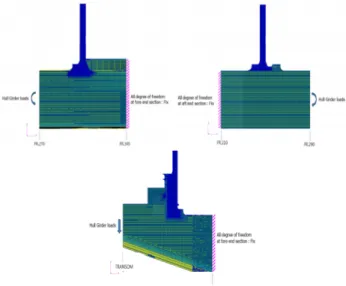
(5) North-Western Australia 해상에 운용되는 Offshore Crane Pedestal 설계. 3.6 Hull girder design loads Hull girder effect including still water and wave hull girder load is taken into account to maximize the longitudinal stress on cargo deck in way of the crane pedestal foundations. The applied total hull girder loads of each analysis model are derived from “Hull girder load calculation” at the respective target position.. 3.7 Hull acceleration Combinations of accelerations should be done taking into account the phase shifts between the different motions and the location to the motion center.. 4. Boundary Condition Fig. 9 Maximum Deflection during Crane Operations. 3.4 Topside module reaction adjacent to crane pedestals. For Forward Crane Pedestal, the target location for hull girder load is at fore end section in way of the crane pedestal foundation and the target bending moments are applied at the after end section of FE model because the configuration of respective sections at the considered area is not changed rapidly. All nodes of fore end section of FE. Some module support stools are integrated with Crane pedestal structures. In order to ensure a sufficient strength of crane pedestal structures combined with module support structures, the reaction loads of Module Support Stools in way of crane pedestal foundations are take into account in the FE model.. 3.5 Wind load According to DNV-RP-C205, the wind speed and pressure with 1 minute mean value is considered as per respective environment conditions and pedestal heights. The wind loads act on the external surface of pedestal structures according to the load directions with 45 degree interval.. model are considered as all fixed conditions for translation and rotation. For Mid Crane Pedestal, the target location for hull girder load is at fore end section in way of the crane pedestal foundation and the target bending moments are applied at the fore end section of FE model. All nodes of after end section of FE model are considered as all fixed conditions for translation and rotation. For Aft Crane Pedestal, the hull girder effect is considered by applying the vertical forces at the aft end (i.e. Neutral axis of transom) area because the configuration of respective sections from transom to the fore end section of FE model is rapidly changed. The applied vertical forces are derived from dividing the hull girder bending moments into the longitudinal length from transom to the target position of aft end section in way of AFT crane pedestal foundation and these are to compensate practical hull girder effect along FPSO’s longitudinal distance of considered. And all nodes of fore end section of FE model are considered as all fixed conditions for translation and rotation. The boundary conditions applied to FE models of respective crane pedestal foundations are shown in the. Fig. 10 Wind Loads Applied on FE model. 38. Fig. 11.. 대한조선학회 특별논문집 2015년 9월.
(6) 송준호・김용운・이경석・김만수. In case of plated structures, the buckling strength for structural members in each limit state is to be verified by DNV-RP-C201. The strength criteria are as follows; . where, and . Where, = Acceptable usage factors. = Design load effect inclusive load factors = Ultimate strength exclusive safety factors In case of cylindrical shells, the buckling strength for. Fig. 11 Boundary Condition. 5. STRUCTURAL EVALUATION. structural members is to be verified by DNV-RP-C202. The plots of maximum stress according to directions of applied loads are shown in Fig. 12. The maximum nominal stress level is about 90 % of allowable value and Maximum peak stress has the value below 130% of allowable nominal stress based on DNV rule. The allowable criteria for yielding, buckling strength and. and project specification.. the relative deflection of crane pedestal structure is defined in accordance with DNV-OS-C102 and Project Specification considering the limit states of LRFD method and mesh size of element. The equivalent stresses derived from structural analysis results have to be complied with the yield criteria as following formula. Material factors for Ultimate Limit State(ULS) and Accidental Limit State(ALS) are applied as 1.15 and 1.0 respectively. For SLS condition, the material factor of 1.5 is applied in accordance with DNV-RP-C102. The equivalent stress (von-Mises stress) is defined as follows; . Where,. Fig. 12 Maximum Yielding Stress Plots. 6. Failure Mode Analysis. = Nominal normal stress in x-direction = Nominal normal stress in y-direction = Shear stress in the x-y-plane. In order to keep the crane operator’s safety during an accidental overloading of the crane, it shall be ensured that the crane pedestal and foundation remains intact during. According to DNV-OS-C102, the criteria of yield strength are follows; ≤ . Where, = Nominal equivalent stress. failure of other components of the crane. The failure loads resulted from the failure mode analysis according to “EN13852” code are provided by the crane vendor and the structure should be designed to withstand the failure loads resulted in an accidental overloading. If the maximum bending moment derived from reaction loads of failure mode. = Material factor, 1.15(ULS), 1.0(ALS), 1.5(SLS). is smaller than the ultimate moment at the considered pedestal foundation, it would be estimated that the structure. = Yield stress of the material (minimum of yield strength). does not form a plastic hinge which is no resistance to. Special Issue of SNAK, September 2015. 39.
(7) North-Western Australia 해상에 운용되는 Offshore Crane Pedestal 설계. 8. Conclusions. further bending. The representative plans of pedestal structure for failure mode check and shape factor of sections are shown in Fig. 13 and Fig. 14.. Traditionally, high quality and strict criteria for offshore structures are required according to Oil Major Client’s conservative inclination. In spite of this tough situation on engineering. and. fabrication. of. offshore. structures,. Contractor needs to have optimized solutions with Client’s satisfaction. Based on our valuable experience of the design for crane pedestal foundation operated in North-western. Australia. offshore,. the. technical. considerations are introduced in this paper. Of course, the huge amount of work volumes for strength analyses remains a risk on project schedule. If engineers take advantage of these valuable experiences, it would be a good practice for the future engineering of crane pedestal structure operated in the similar offshore area.. Fig. 13 Representative Plans for Failure Mode Check. References Det Norske Veritas (2011). “Offshore Standard C101 Design of Offshore steel Structures, General (LRFD Method)”. Det Norske Veritas (2008). “Offshore Standard C102 Structural Design of Offshore Ships”. Det Norske Veritas (2002). “Recommended Practice C102. Fig. 14 Shape Factor of Sections. 7. Fatigue Analysis. Structural Design of Offshore Ships”. Det Norske Veritas (2010). “Recommended Practice C201 Buckling strength of plated structures”. Det Norske Veritas (2010). “Recommended Practice C202. Fatigue analysis is carried out for the foundations of crane pedestal which are designed to meet the fatigue design requirements in API Spec. 2C. The stress range for fatigue check is calculated by the difference between onboard loads with 50% of SWL and unloaded. These loads including wind load are provided from crane vendor. The operation scenario and the probability of crane boom direction for cranes are applied based on API Spec. 2C. In order to determine the critical locations, all of the hot spots are sorted by their details and finally, the check. Buckling strength of Shells”. Det Norske Veritas (2010). “Recommended Practice C204 Design Against Accidental Loads”. Det Norske Veritas (2010). “Recommended Practice C205 Environmental Conditions and Environmental Loads”. Daewoo Shipbuilding Marine Engineering Co. (2014). “Fatigue Analysis for FPSO offshore parts: Crane Pedestal”. American Petroleum Institute (2012). “Specification 2C Seventh Edition October 2012: Offshore Pedestal-mounted Cranes”. locations are selected from the resultant stress level for each operating load and strength analysis results. Total fatigue damage of crane pedestal foundation is calculated by summing up all damages considering wave induced loads and crane operating loads. 송준호. 40. 김용운. 이경석. 김만수. 대한조선학회 특별논문집 2015년 9월.
(8)
수치
+3
관련 문서