Introduction
The chairside CAD/CAM system is widely used for single-visit restorations in dental clinics and con- tinually changes the paradigm of dental restoration procedures.1 It was introduced in the early 1980s and had critical limitations in terms of marginal fit and fracture resistance as compared to conventional restorations.2 However, continuous research and tri- als have resolved these problems currently.3-5 The
reported 3-year and 17-year survival rates of CAD/
CAM restorations are 97.0% and 88.7%, respectively.6,7 Because of technical progress, it has been easier, quicker, and lately, more accurate, for clinicians to place such restorations. CAD/CAM systems can re- duce the number of visits and chair-time, and more- over, allow for single-visit restorations.
Various materials have been developed for use with CAD/CAM systems.8 The use of contemporary materials has led to better performance with regard
*Correspondence to: Duck-Su Kim
Associate Professor, Department of Conservative Dentistry, School of Dentistry, Kyung Hee University, 26 Kyungheedae-ro, Dongdaemun-gu, Seoul, 02447, Republic of Korea
Tel: +82-2-958-9330, Fax: +82-2-960-5108, E-mail: [email protected] Received: February 26, 2020/Last Revision: April 6, 2020/Accepted: May 1, 2020
chairside computer-aided design/computer-aided manufacturing (caD/
caM)-based restoration of anterior teeth with customized shade and surface characterization: a report of 2 cases
Hyun-Jung Kim1, Ji-Hyun Jang2, Gil-Joo Ryu3, Kyoung-Kyu Choi2, Duck-Su Kim2*
1Department of Conservative Dentistry, Kyung Hee University Dental Hospital, Seoul, Republic of Korea
2Department of Conservative Dentistry, School of Dentistry, Kyung Hee University, Seoul, Republic of Korea
3GoodWill Dental Hospital, Busan, Republic of Korea
Over the last 30 years, the use of chairside computer-aided design (CAD) and computer-aided manufacturing (CAM) systems has evolved and has become increasingly popular in dentistry. Although CAD/CAM restorations have been used in the anterior dentition, satisfying the esthetic requirements of clinicians and patients, where the restorations are limited to the chairside, remains a challenge. To reproduce multi-shades of CAD/CAM restorations in the clinic, a preliminary experiment to express several shades on A2 lithium disilicate (LS2) blocks using a staining kit was performed. After measurement of the CIE L*a*b* value of specimens, it was compared with that of the commercial shade guide. This report presents two cases with individual customization of shade and surface characterization of the CAD/CAM restorations using predictable methods based on the preliminary experimental data.
The anatomical shape of restoration was obtained from ‘copy and paste technique’ and ‘mirror image acquisition technique’. All treatment procedures and fabrication of restorations performed in this report were executed in the clinic itself. (J Dent Rehabil Appl Sci 2020;36(2):128-37)
Key words: anterior dentition; computer-aided designing; computer-aided manufacturing; shade; surface characterization; shade characterization
Copyright© 2020 The Korean Academy of Stomatognathic Function and Occlusion.
It is identical to Creative Commons Non-Commercial License.
cc
to esthetic and mechanical properties compared with those used in the past. However, the monochromatic shade of contemporary materials creates difficul- ties for clinicians working in the clinic, who have to ensure that the CAD/CAM restorations mimic the natural appearance of teeth. Additional staining pro- cedures are often required to reproduce the natural shade.
In the case reports described herein, two predict- able methods were used to reproduce a natural-look- ing restoration in the anterior dentition. The “copy and paste technique; using an old restoration design image already acquired before operation,” and the
“mirror image acquisition technique; using a scanned image of the contralateral tooth” were used to ob- tain the required shape and contour.9 In addition, a preliminary experiment of shade difference analysis using CIE L*a*b* measurement was performed and utilized to mimic the natural shade.10
Case Report
Case 1
A 35-year-old man presented to the dental hospital
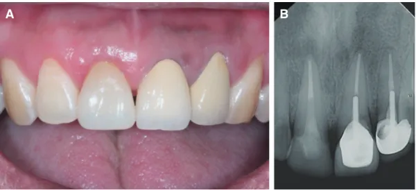
with intermittent gingival pain in the region of the maxillary right central incisor. The tooth had under- gone root canal treatment 8 - 9 years ago, followed by a ceramic crown restoration (Fig. 1A). On clinical examination, the teeth were tender to percussion, with tenderness on palpation of the buccal gingiva.
Radiographic examination revealed periapical radio- lucency of the maxillary right central incisor and an ill-fitting margin of the restoration (Fig. 1B). A diag- nosis of symptomatic apical periodontitis with recur- rent cervical caries was made. A non-surgical root ca- nal retreatment and placement of a new CAD/CAM restoration were planned. Preliminary scan of the old restoration was performed with an intraoral scanner (CEREC AC omnicam; Dentsply Sirona, Charlotte, USA) to copy the old restoration before removal of the old crown (Fig. 1C, 1D).
The neighboring teeth, maxillary left central and lateral incisors were previously restored with por- celain-fused-to-metal crowns, and the restorations showed a grayish hue along the gingival margin of the restorations. Replacement of both the maxillary central incisor restoration and left lateral incisor res- toration was recommended to the patient for esthetic purposes, but he declined the replacement of the
Fig. 1. Preoperative images. (A) Intraoral clinical photo and (B) Periapical radiograph. Note the periapical radiolucency on the apex of the maxillary right central incisor. (C) and (D) Occlusal and labial views of intraoral 3-dimensional scan images before removing the old restoration.
A B
C D
maxillary left central and lateral incisor restorations.
Thus, the replacement of only the maxillary right central incisor restoration was planned. Lithium disil- icate (LS2) block (IPS e.max CAD; Ivoclar Vivadent, Schaan, Liechtenstein) was selected because of its high mechanical properties,11 but its monochromatic shade would have impeded the ability of the restora- tion to mimic the natural shade of the adjacent teeth.
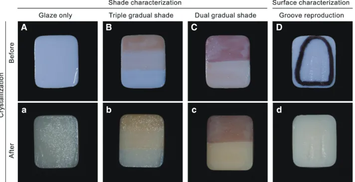
Therefore, to mimic the natural shade, a prelimi- nary experiment was performed on an A2 low trans- lucent (LT) LS2 block. Four 3-mm thick specimens were fabricated using a high-speed diamond saw (Isomet 5000; Buehler, Lake Bluff, USA). Shade cus- tomization, using glaze paste and staining kit (IPS e.max CAD Crystall/Shades, Stains, Glaze and Glaze Liquid; Ivoclar Vivadent), and surface characteriza- tion were performed on the block as follows (Fig. 2):
Color of the 4 specimens, before and after crystal- lization, was assessed by the CIE L*a*b* values ob-
Fig. 2. Experimental shade and surface characterization on lithium disilicate (LS2) blocks. (A) Glaze only; application of an even layer of glaze paste, (a) after crystallization. (B) Three-tone gradual shade; application of double and single coat of shade 1 in the cervical and middle third, respectively. Application of one coat of blue incisal shade in the incisal third, (b) after crystallization. (C) Two-tone gradual shade; application of one coat of mahogany stain on the upper half, and one coat of copper stain on the lower half of the A2 lithium disilicate block, (c) after crystallization. (D) Surface characterization; surface roughening of the restoration using diamond point (F102R; Shofu, Kyoto, Japan) to reproduce the developmental grooves, (d) after crystallization.
A B C D
a b c d
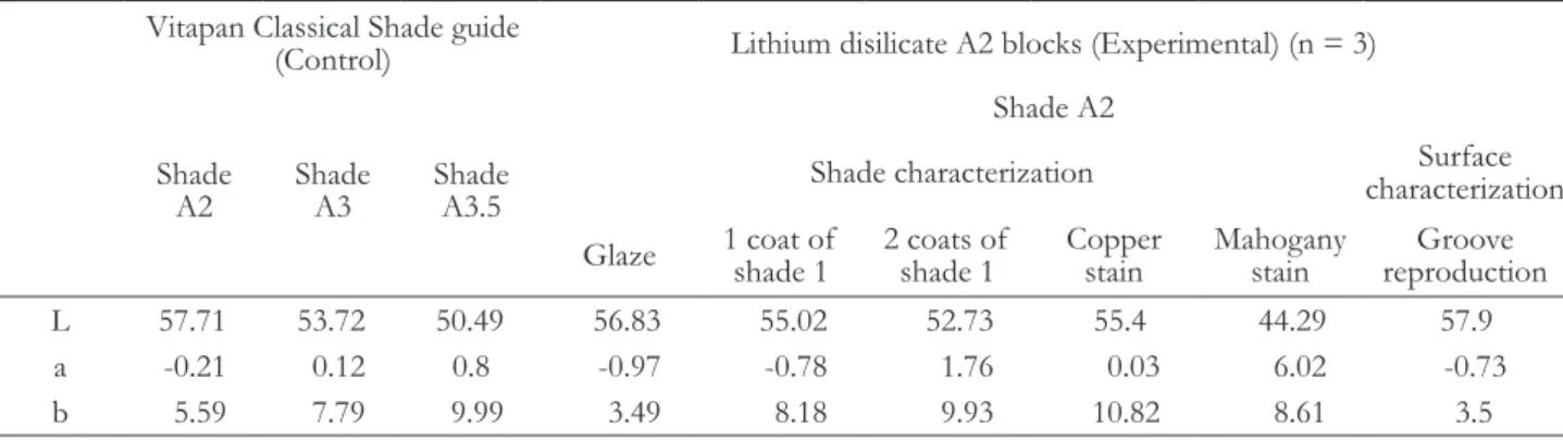
tained using a spectrophotometer (NF999; NIPPON DENSHOKU, Tokyo, Japan). The average CIE L*a*b* value obtained was compared with that of the Vitapan classical shade guide (Vita Zahnfabrik, Bad Säckingen, Germany).
In the following equation, E represents the CIE L*a*b* color value of the experimental block, and V represents that of the Vitapan shade guide tap.10
∆E = √(L*E - L*V)2 + (a*E - a*V)2 + (b*E - b*V)2
The results are shown in Tables 1 and 2. Briefly, the color value of 1 coat of shade 1 on the A2 LT LS2 block was most similar to that of the Vita A3 shade (∆E = 1.62), whereas 2 coats of shade 1 on the block were most similar to the Vita A3.5 shade (∆E = 2.44).12 In this experiment, the specimen that underwent surface characterization showed increased L* value as compared to the specimen that was only glazed. Copper and mahogany-colored stain-
ing caused severe discrepancy in values. In this case, surface characterization, for reproducing the micro- anatomy and application of shade 1 and for shade- matching of the restoration, was adopted according to the experimental results.
Non-surgical root canal retreatment was performed on the maxillary right central incisor (Fig. 3A, 3B) and followed with fiber post cementation (DT Light- Post; Bisco, Schaumburg, USA) and resin core resto- ration (Z100; 3M ESPE, St. Paul, USA). After crown preparation, an intraoral scan was performed and a conventional final impression of the maxillary right central incisor, using polyvinyl siloxane (Imprint 4;
3M ESPE), was taken. The cast model was fabricated from the conventional impression for experimental purpose. The shade of the maxillary right lateral incisor was recorded using a digital shade-matching device (Vita Easyshade V; VITA Zahnfabrik), as a reference for the shade determination of the LS2 crown. Under the “measurement on tooth area”
mode, the shades in the incisal, middle, and cervical
thirds of the maxillary right lateral incisor were re- corded. The shade in the cervical third was recorded as A3.5, middle third as A3, and incisal third as A2 with translucency. Thereafter, a provisional crown was fabricated for the maxillary right central incisor.
The new crown was fabricated with the CAD/
CAM system (CEREC MC X; Dentsply Sirona), us- ing the A2 LT LS2 block. According to the results obtained from the previous experiment, surface characterization was imparted to the middle third of the labial surface of the restoration, using a dia- mond point bur (F102R; Shofu, Kyoto, Japan). In the cervical third of the restoration, 2 coats of shade 1 were applied to reproduce the A3.5 shade. In the middle third of it, 1 coat of shade 1 was applied to reproduce the A3 shade. In the incisal third of it, a blue shade was applied for reproducing incisal trans- lucency (Fig. 3C). Thereafter, crystallization was per- formed in a ceramic furnace (Programat P310; Ivo- clar Vivadent), and the crown was allowed to cool for 10 min. Further, 9.5% hydrofluoric acid (Porcelain Table 1. Lab values of surface characterized lithium disilicate A2 blocks and Vita Shade guide
Vitapan Classical Shade guide
(Control) Lithium disilicate A2 blocks (Experimental) (n = 3)
Shade
A2 Shade
A3 Shade
A3.5
Shade A2
Shade characterization Surface
characterization Glaze 1 coat of
shade 1 2 coats of
shade 1 Copper
stain Mahogany
stain Groove reproduction
L 57.71 53.72 50.49 56.83 55.02 52.73 55.4 44.29 57.9
a -0.21 0.12 0.8 -0.97 -0.78 1.76 0.03 6.02 -0.73
b 5.59 7.79 9.99 3.49 8.18 9.93 10.82 8.61 3.5
Table 2. CIE L*a*b*-based color difference between the surface characterized lithium disilicate (LS2) A2 blocks and Vita
Shade guide (∆E value)
∆E determined with Vitapan guide taps
Shade characterization on A2 LS2 block Surface characterization Glaze 1 coat of
shade 1 2 coats of
shade 1 Copper
stain Mahogany
stain Groove
reproduction
∆E with A2 tap 2.40 3.78 6.9 5.73 15.11 2.16
∆E with A3 tap 5.41 1.62 2.88 3.47 11.16 6.05
∆E with A3.5 tap 9.25 5.13 2.44 5.04 8.23 9.97
etchant; Bisco) was applied to the internal surface of the restoration for 20 s; the surface was then washed with air-water spray and dried. Thereafter, a silane coupling agent (Monobond-S; Ivoclar Vivadent) was applied for 60 s, after which the surface was thor- oughly air-dried. 37% phosphoric acid (ETCH-37™;
BISCO) was applied to prepared tooth surface for 20 s;
the surface was then rinsed for 20 s and air-dried.
Thereafter, dentin adhesive (All-Bond Universal; Bis- co) was applied to the tooth surface according to the
manufacturer’s instructions. Dual-cure resin cement (Duo-Link; Bisco) was mixed in a spiral syringe and applied to the internal surface of the crown, and it was seated on the prepared tooth. Initial light curing was performed for 5 s, and the excess cement was removed with a dental explorer. The resin cement was polymerized from each margin using visible light with an irradiance of 1200 mW/cm2 (Bluephase G2;
Ivoclar Vivadent) (Fig. 4A, 4B). The occlusion was checked and adjusted after the crown was cemented.
Fig. 3. (A) Periapical radiographies of working length determination, (B) Periapical radiographies of the endodontic canal filling, (C) Photography of staining of the lithium disilicate crown.
A B C
Fig. 4. (A) Intraoral photo and (B) Periapical radiograph after final cementation.
A B
Case 2
An 81-year-old woman presented at the dental clinic with a fractured maxillary left central incisor.
Clinical and radiological examinations revealed a complicated crown fracture of the maxillary left cen- tral incisor (Fig. 5A, 5B). A non-surgical root canal treatment followed by a CAD/CAM crown restora- tion in a single visit were planned.
Single-visit root canal treatment was performed because there was no evidence of periapical pathosis (Fig. 5B). Fiber post (DT Light-Post) cementation, resin core (Z100) restoration, and crown preparation were performed on the maxillary left central incisor.
Digital impression of the tooth was taken with an intraoral scanner (CEREC AC omnicam) (Fig. 5C).
To determine the shade of the LS2 crown, a digital shade matching device (Vita Easyshade V) was used on the adjacent maxillary right central incisor. Shades of the cervical third and the mesial and distal mar- ginal ridges were recorded as A3.5, and those of the
middle and incisal third were recorded as A3.
The “copy and paste technique” could not be used because of the fractured maxillary left central incisor.
Instead, the “mirror image acquisition technique”
was performed on the intact maxillary right central incisor with the CAD/CAM software (Fig. 5D). A new LS2 crown was milled with the CAD/CAM system (CEREC MC X), using an A2 LT block. The newly fabricated crown was tried-in before crystal- lization. Occlusion of the pre-crystallized crown was checked and carefully adjusted. The surface texture of the maxillary right central incisor was referred to for the surface characterization of the maxillary left central incisor. It showed vertical striae and surface irregularity. The surface characterization of the pre- crystallized LS2 crown was performed with a high- speed diamond bur (F102R). Thereafter, the staining procedure was performed. One coat of shade 1 was applied to the entire labial surface to reproduce the A3 shade. An additional coat of shade 1 was ap- plied on the cervical third and both marginal ridges
Fig. 5. (A) Intraoral photo and (B) Periapical radiographs. (C) Intraoral scan image after tooth preparation and (D) Virtual placement of the crown on computer-aided designing software using the “mirror image acquisition technique.”
B A
D C
to reproduce the A3.5 shade. The characterized and glazed LS2 crown was crystallized in a ceramic fur- nace (Programat P310) and was allowed to cool for 10 min.
The internal surface of the crown was etched with 9.5% hydrofluoric acid (Porcelain etchant) and treat- ed with a silane coupling agent (Monobond-S). The prepared tooth surface was etched with 37% phos- phoric acid (ETCH-37™), rinsed with oil-free water for 20 s, and air-dried. Dentin adhesive (All-Bond Universal) was applied and light-cured. Final cemen- tation was performed with a dual-cure resin cement (Duo-Link) under visible light with an intensity of 1200 mW/cm2 (Bluephase G2) (Fig. 6A, 6B).
Discussion
There are 4 different methods for dental surface characterization in CAD/CAM restorations: cut- back and layering, polishing and glazing, internal characterization, and external characterization.13 In- ternal characterization has the possibility of decreas- ing cement space due to internal add-on of surface colorants, and therefore, is rarely used in monolithic CAD/CAM restorations.13 To reproduce the trans- lucency of the anterior teeth, the cut-back and lay- ering technique is often recommended.14 However,
this technique needs a dental technician’s assistance.
Thus, the ultimate purpose of a single-visit chairside CAD/CAM restoration is thwarted because of these complicated processes. The external characterization method provides a simple and convenient way to ac- complish superior esthetics in anterior dentition. For example, it is possible to mimic incisal translucency using an blue shade.15 Good understanding of the shade reproduction properties of the staining kit may enable the expression of multiple shades on the restoration.
According to the experimental design and results in this report, individual shade guide taps can be fabri- cated in clinics with ceramic blocks that are preferred by clinicians. This enables the prediction and esthetic fabrication of the CAD/CAM in clinics. In the two cases described here, we used only the A2 shade blocks. Using a staining kit, we reproduced darker shades like A3 and A3.5 on an A2 block. This tech- nique may be used in cases where perfectly matched LS2 block are unavailable. Moreover, in clinics, this technique will help express multi-shade of the natu- ral teeth on an LS2 monolithic crown.
LS2 staining material was composed of oxide and glycol.16 According to a recently published study, repeated staining applications might reduce the mechanical strength of LS2. Single step of staining Fig. 6. (A) Intraoral photo and (B) Periapical radiograph after final cementation.
A B
and crystallization would maintain a better mechani- cal property due to interaction between the staining paste and LS2 surface.16 The exact shade prediction used in this report will prevent the repeated staining for shade correction.
Another noteworthy finding in both the cases is that in an LS2 block, glazing after surface charac- terization can increase the brightness as compared to glazing alone. It has been postulated that surface characterization, which is mainly used in anterior composite resin restorations, may increase the bright- ness of the LS2 block.17 Brightness of the CAD/
CAM block is determined by two factors: the light transmission through the block and the scatter of re- flected light on its surface.18,19 According to Awad et al., surface roughness could decrease the translucency of the CAD/CAM materials.20 Surface characteriza- tion can directly increase the scattered reflection by increasing the surface roughness and also decrease the translucency and light transmission of the block.
Thus, the increase in brightness after surface char- acterization can be attributed to these factors. This effect may also be considered when surface charac- terization is necessary.
Other esthetic ceramic materials such as specific types of feldspathic ceramics and leucite-reinforced ceramics are available and are referred to as “multi- shade.” However, because these “multi-shade” blocks exhibit a gradual shade change from the cervical to incisal regions, they cannot reproduce abrupt shade changes or complex natural tooth shades.
When using the CAD/CAM systems, there are instances where the design proposed by the soft- ware does not perfectly mimic the adjacent teeth.
Most CAD/CAM systems provide different design algorithms. They offer a “pre-operative scan” that can be applied to conventional preliminary alginate impressions. In the CAD/CAM software, clinicians can use the pre-operative design of an old restora- tion or original natural anatomy as the new restora- tion design. This report described this technique as the “copy and paste technique”.9 It can be used in patients with an intact tooth structure before the procedure. In patients who have structural tooth loss, clinicians can scan and use the anatomy of the
contralateral tooth to digitally create a mirror image.
Here, it is called as the “mirror image acquisition technique”. These suggested designs maximized patient satisfaction and comfort and minimized the necessity for occlusal adjustment.12
Conclusion
In both the cases presented, CAD/CAM restora- tions were used to restore anterior teeth with high esthetic expectations. The anatomical shape of the restoration was conveniently and esthetically re- produced with the “copy and paste technique” and
“mirror image acquisition technique.” To reproduce a multi-shade nature of the restoration, surface char- acterization and staining procedure were utilized, ac- cording to the results of preliminary shade compari- son analysis. These methods can assist clinicians in fabricating esthetic and natural-looking restorations in the anterior dentition.
ORCID
Hyun-Jung Kim https://orcid.org/0000-0002-7674-9363 Ji-Hyun Jang https://orcid.org/0000-0002-4672-3381 Duck-Su Kim https://orcid.org/0000-0001-9386-6062
References
1. Mörmann WH. The evolution of the CEREC sys- tem. J Am Dent Assoc 2006;137 Suppl:7S-13S.
2. Siervo S, Pampalone A, Siervo P, Siervo R. Where is the gap? Machinable ceramic systems and con- ventional laboratory restorations at a glance. Quin- tessence Int 1994;25:773-9.
3. Kim JH, Jeong JH, Lee JH, Cho HW. Fit of lithium disilicate crowns fabricated from conventional and digital impressions assessed with micro-CT. J Pros- thet Dent 2016;116:551-7.
4. Tidehag P, Ottosson K, Sjögren G. Accuracy of ceramic restorations made using an in-office optical scanning technique: an in vitro study. Oper Dent 2014;39:308-16.
5. Abdel-Azim T, Rogers K, Elathamna E, Zandine- jad A, Metz M, Morton D. Comparison of the
marginal fit of lithium disilicate crowns fabricated with CAD/CAM technology by using conventional impressions and two intraoral digital scanners. J Prosthet Dent 2015;114:554-9.
6. Otto T, Schneider D. Long-term clinical results of chairside Cerec CAD/CAM inlays and onlays: a case series. Int J Prosthodont 2008;21:53-9.
7. Lu T, Peng L, Xiong F, Lin XY, Zhang P, Lin ZT, Wu BL. A 3-year clinical evaluation of endodonti- cally treated posterior teeth restored with two dif- ferent materials using the CEREC AC chair-side system. J Prosthet Dent 2018;119:363-8.
8. Fasbinder DJ. Materials for chairside CAD/CAM res- torations. Compend Contin Educ Dent 2010;31:702- 4.
9. Poticny DJ, Klim J. CAD/CAM in-office technol- ogy: innovations after 25 years for predictable, es- thetic outcomes. J Am Dent Assoc 2010;141 Suppl 2:5S-9S.
10. Paravina RD, Ghinea R, Herrera LJ, Bona AD, Igiel C, Linninger M, Sakai M, Takahashi H, Tashkandi E, del Mar Perez M. Color difference thresholds in dentistry. J Esthet Restor Dent 2015;27 Suppl 1:S1- S9.
11. Pieger S, Salman A, Bidra AS. Clinical outcomes of lithium disilicate single crowns and partial fixed dental prostheses: a systematic review. J Prosthet Dent 2014;112:22-30.
12. Johnston WM, Kao EC. Assessment of appearance match by visual observation and clinical colorim-
etry. J Dent Res 1989;68:819-22.
13. Goldstein RE. Esthetics in Dentistry. 2nd ed. Ham- ilton; Decker; 2014.
14. Durán Ojeda G, Henríquez Gutiérrez I, Guzmán Marusic Á, Báez Rosales A, Tisi Lanchares JP. A step-by-step conservative approach for CAD-CAM laminate veneers. Case Rep Dent 2017;2017:3801419.
15. Griffin JD Jr. Anterior CEREC CAD/CAM por- celain treatment of GERD eroded teeth. Contemp Esthet 2006;10:32-9.
16. Miranda JS, de Pinho Barcellos AS, Campos TMB, Cesar PF, Amaral M, Kimpara ET. Effect of re- peated firings and staining on the mechanical be- havior and composition of lithium disilicate. Dent Mater 2020;36:e149-57.
17. Sarac D, Sarac YS, Kulunk S, Ural C, Kulunk T.
The effect of polishing techniques on the surface roughness and color change of composite resins. J Prosthet Dent 2006;96:33-40.
18. Brodbelt RH, O’brien WJ, Fan PL. Translucency of dental porcelains. J Dent Res 1980;59:70-5.
19. Fondriest J. Shade matching in restorative dentistry:
the science and strategies. Int J Periodontics Re- storative Dent 2006;23:467-79.
20. Awad D, Stawarczyk B, Liebermann A, Ilie N.
Translucency of esthetic dental restorative CAD/
CAM materials and composite resins with respect to thickness and surface roughness. J Prosthet Dent 2015;113:534-40.
*교신저자: 김덕수
(02447)서울시 동대문구 경희대로 26, 경희대학교 치과대학 치과보존학교실 Tel: 02-958-9330|Fax: 02-960-5108|E-mail: [email protected] 접수일: 2020년 2월 26일|수정일: 2020년 4월 6일|채택일: 2020년 5월 1일
CAD/CAM을 이용한 전치부 수복시 색조 및 표면 특성의 개별화를 시행한 증례
김현정1임상조교수, 장지현2조교수, 류길주3원장, 최경규2교수, 김덕수2* 부교수
1경희대학교 치과병원 치과보존과
2경희대학교 치과대학
3굿윌치과병원
지난 30년동안, CAD/CAM 시스템을 이용한 수복 시스템은 눈부시게 발전하였다. 구치부 수복에서 널리 쓰이던 것과는 달리, 환자와 임상가의 심미적인 요구를 충족해야 하는 전치부 수복 증례에서는 CAD/CAM 시스템을 이용하는데 다소 한계가 있었다. 단일 색조를 가지는 CAD/CAM 수복물에 다양한 색조를 부여하기 위해, A2 lithium disilicate (LS2) 블 록에 staining kit를 이용하여 색조 개별화를 시행하여 다양한 색조를 표현하는 예비실험을 시행하였다. 색조 개별화를 진 행한 시편을 spectrophotometer를 이용하여 CIE L*a*b* 값을 측정한 후, 임상에서 널리 사용되고 있는 shade guide와 비교하였다. 예비 실험 결과를 바탕으로 2명의 환자의 전치부 수복시, 치아의 부위별 색조 재현과 표면 특성의 개별화를
진행한 증례를 소개한다. 수복물의 해부학적 형태는 CAD/CAM 시스템에서 ‘복사 및 붙여넣기 기능’과 ‘거울상 획득 기
능’을 이용하여 디자인하였으며, 이 연구에서 소개하는 모든 임상 및 수복물의 기공과정은 진료실 내에서만 이루어졌다.
(구강회복응용과학지 2020;36(2):128-37)
주요어: 전치부 수복; CAD/CAM 수복; 색조 개별화; 표면 특성 개별화