• 검색 결과가 없습니다.

Time-division Visible Light Communication Using LED Lamp Light

N/A
N/A
Protected

Academic year: 2021

Share "Time-division Visible Light Communication Using LED Lamp Light"

Copied!
6
0
0

로드 중.... (전체 텍스트 보기)

전체 글

(1)

http://dx.doi.org/10.5369/JSST.2015.24.3.145 pISSN 1225-5475/eISSN 2093-7563

Time-division Visible Light Communication Using LED Lamp Light

Seong-Ho Lee

1,+

Abstract

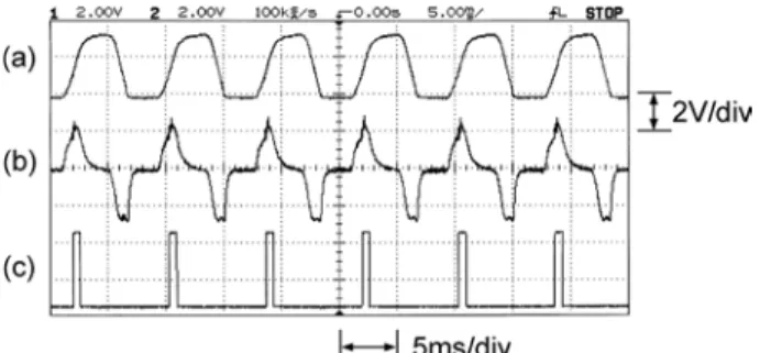
We introduce a new method of time-division visible light communication (VLC) using LED lamp light for the generation of syn- chronizing pulses. The LED lamp, driven by an AC 220-V power line, radiates light that has a 120-Hz frequency component. The pulse generator in each VLC system receives the LED lamp light and generates the synchronizing pulses that are required for time-division transmission of multiple VLC channels. The pulse period is subdivided into several time slots for VLC channels. In experiments, 120- Hz synchronizing pulses were generated using LED lamp light, and three VLC channels were transmitted independently without inter- fering with each other in a condition where the VLC signals overlapped in space. This configuration is useful in constructing multiple wireless sensor networks that are safe and without interference in locations where LED lamps are used for illumination.

Keywords: Visible Light Communication, LED Lamp, Interference, Time-division Transmission, Synchronizing Pulse

1. INTRODUCTION

Visible light communication (VLC) is a communication method in which light sources are used for illumination and communication simultaneously [1-4]. VLC is a type of wireless optical communication in which optical fibers are not used and the optical signals are directly transmitted from light sources to receivers through free space [5].

Recently there have been great advances in semiconductor technology, and high-power light-emitting diodes (LEDs) have been developed to replace conventional lighting facilities such as fluorescent lamps and incandescent lamps. LEDs have many advantages including long lifetime, high efficiency, and small size.

In addition, because of their high-speed modulation capabilities, LEDs have been widely used for light sources in VLC systems.

Because free space is a common transmission media for wireless systems, special methods should be provided in order to prevent crosstalk between adjacent optical channels in an environment where multiple VLC signals overlap in space. In order to prevent

interference between VLC channels, wavelength division, subcarrier-frequency division, and time-division transmission methods have been generally used.

In wavelength-division transmission, each channel uses a light source that emits a predefined wavelength, and in the receiver optical filters are used to suppress optical signals from other channels. White-light LEDs are generally used for indoor lighting;

thus VLC systems with multiple wavelengths may not be practical in a common location.

In subcarrier-frequency-division transmission, different subcarrier frequencies are allocated for VLC channels, and in the receiver electrical filters are used to detect corresponding channel signals. However, the modulation bandwidth of commercial high- power LEDs generally ranges from hundreds of kHz to a few MHz. Because of the relatively low bandwidth of LEDs, the channel spacing may not be wide enough, and system design can be difficult to implement.

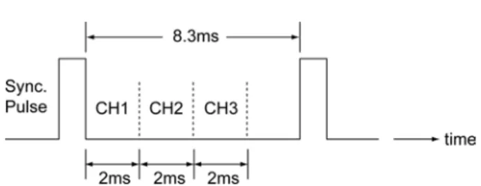
In time-division transmission, time slots are allocated for channels, and each channel transmits and receives data only in predefined time slots. In this scheme, separate synchronizing pulses should be provided in order to define time slots; thus, additional channels are required for sending and receiving synchronizing pulses.

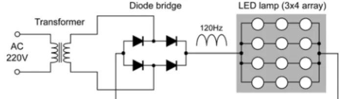
In this paper, we introduce a very simple method to provide synchronizing pulses for multiple VLC systems. The synchronizing pulses are generated from the light of an LED lamp that is installed on the ceiling of a room for indoor lighting.

Generally, LED lamps are connected to AC 220-V 60-Hz power Department of Electronics & IT Media Engineering, Seoul National University

of Science and Technology,

232 Gongneung-ro, Nowon-gu, Seoul 139-743, Korea

+

Corresponding author: [email protected] (Received : May. 10, 2015, Accepted : May. 24, 2015)

This is an Open Access article distributed under the terms of the Creative Commons Attribution Non-Commercial License(http://creativecommons.org/

licenses/bync/3.0) which permits unrestricted non-commercial use, distribution,

and reproduction in any medium, provided the original work is properly cited.

(2)

lines through regulating circuits, and the output light from an LED lamp has the frequency component of the AC power line.

Each VLC transmitter and receiver has a pulse generator. A pulse generator has a phototransistor to receive the LED lamp light, and generates the synchronizing pulses whose repetition frequency is the same that of the LED lamp light. If the LED lamp is driven by a full-wave rectifier connected to an AC 60-Hz power line, the repetition frequency of the synchronizing pulses is 120 Hz, which is twice that of the AC power line. In experiments, the pulse period was subdivided into three time slots, and three segments of VLC channel data at 9.6 kbps were transmitted using the time slots without interference.

This configuration is very simple and easy to use because LED lamps are common lighting facilities in offices or homes, and in indoor or outdoor locations. Using nearby LED lamp light, we can easily construct synchronizing systems for time-division transmission of multiple VLC channels. This configuration is applicable to the construction of multiple wireless sensor networks that are safe without interference between channels.

2. SYSTEM CONFIGURATION

2.1 VLC system configuration

The overall system configuration for time-division transmission of multiple VLC systems is shown in Fig. 1.

The LED lamp was installed on the ceiling and illuminated the entire room. The LED lamp was driven by an AC 220-V power line through a full-wave rectifier circuit. Three VLC transmitters (VLC-Tx1, Tx2, and Tx3) transmitted data to three VLC receivers (VLC-Rx1, Rx2, and Rx3), respectively. Each transmitter and each receiver had its own pulse generator (PG). All of the pulse

generators received LED lamp light simultaneously and generated synchronizing pulses. Three time slots were assigned between pulses, and three VLC channels transmitted data using the predefined time slots.

2.2 LED lamp circuit

Fig. 2 is the schematic diagram of the LED lamp that was fabricated for the experiments.

The LED lamp had a planar 3×4 LED array that was composed of 12 LEDs. All of the LEDs were 1-W white LEDs manufactured by the Helio Corporation. The transformer dropped the AC 220 V to AC 12 V, and the diode bridge converted the AC 60-Hz voltage to AC 120-Hz full-wave rectified voltage. The output voltage of the diode bridge was applied to the LED array.

The LED lamp was installed on the ceiling of the laboratory room and illuminated all of the VLC transmitters and receivers.

2.3 Pulse generator circuit

Fig. 3 is the pulse-generating (PG) circuit that was used in the VLC transmitters and receivers.

A phototransistor (PTR) in the pulse generator circuit received the LED lamp light, and the output voltage appeared across the load resistor R

L

. The output voltage of the phototransistor was amplified and passed through an RC differentiator circuit. The differentiator output voltage showed its peak at the point of the maximum slope in the PTR voltage. The output voltage of the

Fig. 1. Time-division VLC systems using LED lamp light.

Fig. 2. LED lamp circuit.

Fig. 3. Pulse generator circuit.

(3)

differentiator was applied to a threshold circuit, which generated pulses that had the same 120-Hz repetition frequency as the LED lamp light.

The phototransistor was an Oscar OST-1KLA, and the load resistance was 1 k Ω. The amplifier was an LM2904 op-amp. The capacitor C and resistor R in the differentiator circuit were 0.1 μF and 1 k Ω, respectively. The threshold circuit was composed of a 74LS00 gate.

2.4 Pulse generation experiment from LED lamp light The pulse generator produced synchronizing pulses when it was illuminated by the LED lamp light. We observed the voltage waveforms in a pulse generator circuit with an oscilloscope. Fig.

4 shows the observed waveforms.

Fig. 4(a) is the voltage waveform (TP1 in Fig. 3) of the phototransistor illuminated by the LED lamp light. The LED lamp was driven by 220-V AC power through a transformer and a full- wave diode bridge, as shown in Fig. 2. The repetition frequency of the LED lamp light was 120 Hz.

Fig. 4(b) is the output voltage of a differentiator that is composed of a capacitor and a resistor (TP2 in Fig. 3). The peak voltage of the differentiator appeared at the point of the maximum slope in the phototransistor voltage in Fig. 4(a). The output voltage was amplified and applied to a threshold circuit.

Fig. 4(c) is the output voltage of the threshold circuit (TP3 in Fig.

3). The threshold circuit produced pulses with a period of 8.3 ms, which was the inverse of the repetition frequency of 120 Hz. These pulses were used for synchronizing pulses in the time-division VLC systems. Every VLC transmitter and receiver has its own pulse generator, and all of the pulse generators were illuminated by the same LED lamp light and generated the same pulse trains.

Therefore, this configuration simplifies the synchronizing systems for multiple VLC systems in time-division mode.

3. Time-division TRANSMISSION of VLC CHANNELS

3.1 VLC transmitter and receiver circuits Fig. 5 shows the configuration of a VLC transmitter.

In the VLC transmitter, we used 9.6-kbps UART data in non- return-to-zero (NRZ) code format. The transmitted data were modulated in an amplitude-shift-keying (ASK) waveform in which a 100-kHz sinusoidal subcarrier was used. The output voltage of the ASK modulator was applied to a current driver, and modulated the current to an LED array. The LED array was used for the light source. In time-division mode, the VLC transmitter sent data in predefined time slots between synchronizing pulses.

We used an analog switch ADG417 for the ASK modulator, and an FET IRF540 for the current driver. The LED array was composed of six 1-W white LEDs in a 3 ×2 planar array form.

A VLC receiver was installed at a distance of 1 m from the VLC transmitter. Fig. 6 shows the configuration of the VLC receiver.

In the VLC receiver, a photodiode (PD) detected the signal light from the transmitter. The voltage across the load resistor (R) was amplified by an op-amp and filtered by a 100-kHz band pass filter to receive the ASK signal. The ASK signal was applied to an ASK demodulator. The output of the demodulator was the same ASCII code data transmitted from the VLC transmitter. In time- division mode, the VLC receiver accepted data in predefined time

Fig. 4. Waveforms observed in a pulse generator.

(a) Phototransistor voltage (b) Differentiator voltage (c) Generated output pulses

Fig. 5. VLC transmitter.

Fig. 6. VLC receiver.

(4)

slots between synchronizing pulses. The photodiodes used in the receivers were Hamamatsu PIN S6968, the amplifier was made of an OPA228 op-amp, and the band-pass filter was an LC resonant circuit. The ASK demodulator was composed of an envelope detector and a threshold circuit [6].

In order to verify the normal transmission between a VLC transmitter and a receiver, we sent the character “V,” whose ASCII code is 01010110. In UART transmission format, the least significant bit is sent first. Thus the bit sequence was changed to 01101010, and one start bit 0 was added in front of the character.

The resulting bit sequence was 001101010. “High voltage (H)”

was assigned to bit 0, “low voltage (L)” was assigned to a bit 1, and the waveform of the character “V” became HHLLHLHLH.

We observed the voltage waveform in the VLC transmitter and receiver with an oscilloscope. Fig. 7 shows the observed waveforms.

Fig. 7(a) is the voltage waveform of the character “V” that was applied to the input of the VLC transmitter (TP1 in Fig. 5). The data was modulated by a 100-kHz ASK modulator. Fig. 7(b) is the output voltage of the ASK modulator (TP2 in Fig. 5). When the data was in a “high” state, a 100-kHz sinusoidal wave was present. When the data was in a “low” state, 0 V appeared.

Fig. 7(c) is the ASK waveform detected in the receiver (TP1 in Fig. 6). This signal was applied to an ASK demodulator. Fig. 7(d) is the output waveform of the ASK demodulator (TP2 in Fig. 6).

This waveform is the same as the character “V” that was sent from the VLC transmitter.

3.2 Time-division VLC transmission with synchronizing pulses

Three VLC transmitters and receivers were installed as shown in Fig. 1. The three VLC transmitters were installed side by side

on a table. The distance between adjacent VLC transmitters was approximately 10 cm. Three receivers were also installed side by side at a distance of 10 cm. The distance from the transmitters to the receivers was approximately 1 m. The signal lights from the three VLC transmitters overlapped each other at the position of the VLC receivers. An LED lamp was installed on the ceiling.

The height from the table to the LED lamp was approximately 1.2 m. The LED lamp light illuminated all of the transmitters and receivers. The pulse generators in the VLC transmitters and receivers generated synchronizing pulses for time-division transmission. The pulse period was 8.3 ms, which corresponds to the inverse of the 120-Hz frequency of the LED lamp light. We defined the first 2 ms from the falling edge of the pulse as VLC channel 1 (CH1). The second and the third 2-ms time slots were defined as CH2 and CH3, respectively, as shown in Fig. 8.

The relation between the bit rate (B) and the number of time- division channels (N) can be calculated as follows. One bit time is 1/B sec, and 1 byte occupies 9 × 1/B s, including one start bit.

If we set the guard time between channels equal to 1 byte time, the total time required for N channels is (9 × 1/B) × 2N. This should be smaller than a pulse period (T); that is,

(1)

where the pulse period T = 1/f, and f is the pulse repetition frequency. In this system, the pulse repetition frequency was f = 120 Hz, and we used a bit rate of B= 9.6 kbps. Substituting these in equation (1), the number of time-division channels is

(2)

In experiments, we used three channels in time-division transmission. We sent characters “\tCH1-123\r\n” in CH1,

“\tCH2-ABC\r\n” in CH2, and “\tCH3-VLC\r\n” in CH3.

Characters “\t” (tab), “\r” (carriage return), and “\n” (line feed) were included in the character strings to adjust the display position on the monitors. We observed the voltage waveforms with an oscilloscope. Fig. 9 shows the observed waveforms.

9 B --- 2N T × <

N 1 2 --- B

--- 9 1 --- f

×

×

< = 4.44 Fig. 7. Waveforms in a VLC transmitter and a receiver.

(a) Transmitted data (character “V”)

(b) ASK modulated waveform of transmitted data (c) Received ASK waveform

(d) Demodulated data (character “V”)

Fig. 8. Time slots between synchronizing pulses.

(5)

Fig. 9(a) shows the synchronizing pulses from a pulse generator. These are the same pulses as in Fig. 4(c) but with a different time scale.

Fig. 9(b) shows the ASK waveforms from CH1, CH2, and CH3. This waveform was observed with a separate photodetector in order to check the time-division operation. We can see that each channel transmits its data at the given time slots. The data rate was 9.6 kbps, and a 100-kHz subcarrier was used for ASK modulation.

Fig. 9(c), (d), and (e) show the demodulated output signals in the receivers of CH1, CH2, and CH3, respectively. Three segments of channel data were transmitted independently without interfering with each other. We applied the demodulated signals from the three receivers to the serial ports of PC monitors. Fig. 10 shows the characters displayed on the monitors.

Fig. 10 (a), (b), and (c) show the data sent by the transmitters of CH1, CH2, and CH3, respectively. We can see that each channel transmitted and received its data without interference. Fig.

11 shows the circuits used in the experiments.

Fig. 11(a) is the LED lamp that was used for illuminating the transmitters and receivers to generate synchronizing pulses. In the

LED lamp, we used a 3×4 LED array that was composed of 12 white 1-W LEDs.

Fig. 11(b) shows the circuit of the VLC transmitter. We used a 2 ×3 LED array for the light source of the VLC transmitter. A phototransistor viewing upward was the light detector that received LED lamp light to generate synchronizing pulses.

Fig. 11(c) shows the circuit of the VLC receiver. For VLC signal detection, we used a PIN photodiode (Hamamatsu S6968) in the VLC receiver. In the receiver circuit, a phototransistor was also used in order to receive the LED lamp light for synchronizing pulse generation.

4. CONCLUSIONS

In this paper, we introduced a new time-division VLC transmission method in order to prevent interference between adjacent optical signals. The synchronizing pulses for time division were generated from an LED lamp light that was installed near the VLC systems. In experiments, we generated 120-Hz synchronizing pulses from an LED lamp light and defined the time slots for three VLC channels. Three segments of VLC channel data at 9.6 kbps were transmitted successfully without interfering with each other.

Nowadays, high-power LED lamps are replacing conventional light facilities such as fluorescent lamps and incandescent lamps.

Thus this scheme simplifies the synchronizing system for time- division VLC systems. This configuration is very simple and applicable to the construction of multiple wireless sensor networks using VLC channels.

Fig. 9. Waveforms in a VLC receiver.

(a) Synchronizing pulses

(b) ASK waveforms of CH1, CH2 and CH3 (c) Demodulated data of CH1

(d) Demodulated data of CH2 (e) Demodulated data of CH3

Fig. 10. Data displayed on monitors:

VLC CH1, (b) VLC CH2, and (c) VLC CH3.

Fig. 11. Circuits used in experiments:

LED lamp, (b) VLC transmitter, and (c) VLC receiver.

(6)

ACKNOWLEDGMENT

This study was supported by the Research Program funded by the Seoul National University of Science and Technology.

REFERENCES

[1] T. Komine and M. Nakagawa, “Fundamental analysis for visible-light communication system using LED lights,”

IEEE Trans. Consumer Electron., Vol. 50, No. 1, pp. 100- 107, 2004.

[2] Y. K. Cheong, X. W. Ng, and W. Y. Chung, “Hazardless

biomedical sensing data transmission using VLC,” IEEE Sensors Journal, Vol. 13, No. 9, pp. 3347–3348, 2013.

[3] Seong-Ho Lee, “Time division transmission of visible light channels using power line frequency,” Journal of Sensor Science and Technology, Vol. 23, No. 5, pp. 349-355, 2014.

[4] K. Suzuki, K. Ashahi, and A. Watanabe, “Basic study on receiving light signal by LED for bidirectional visible light communications”, Electronics and Communications in Japan, Vol. 98, No. 2, pp. 1-9, 2015.

[5] J. M. Kahn and J. R. Barry, “Wireless infrared commu- nications”, Proc. IEEE, Vol. 85, No. 2, pp. 265-298, 1997..

[6] F. Yuan, “Design techniques for ASK demodulators of pas-

sive wireless microsystems: a state-of-the-art review,” Ana-

log Integr. Circ. Sig. Process, Vol. 63, No.1, pp. 33-45,

2010.

수치

Fig. 3 is the pulse-generating (PG) circuit that was used in the VLC transmitters and receivers
Fig. 5. VLC transmitter.
Fig. 8. Time slots between synchronizing pulses.
Fig. 9. Waveforms in a VLC receiver.

참조

관련 문서

(4) Apply RF pulses (electromagnetic waves) for exciting spins in the position of which resonant frequency is same to one of the applied pulses.. (5) Turn off the pulses then

Most submerged lamp system have a fundamental fouling problem and due to the absorption of UV light by fouling materials on the quartz sleeve, germicidal power of UV

Hakim, The Story of Science – – Newton at the Center, Newton at the Center,... Thermal

LED(Light Emitting

The purpose of this study is to compare the degrees of conversion of light curing resin cement specimens cured by the light transmitted different thickness of zirconia

Fluorescence from initial carious lesion of teeth illuminated by an LED light was observed through barrier filter and the number of teeth showing lesion,

A Study on the Temperature Dependent for Reliability Improvement of SMPS for LED Lamp.. 2017

• LED, Light Emitting Diode embedded GFRP, Glass Fiber