Propulsion System Design and Optimization for Ground Based Interceptor using Genetic Algorithm
Qasim Zeeshan
1Dong Yunfeng
2Khurram Nisar
31
PhD candidate, Beijing University of Aeronautics & Astronautics, BUAA, P.R.China
2
Professor, Beijing University of Aeronautics & Astronautics, BUAA, P.R. China
3
PhD candidate, Beijing University of Aeronautics & Astronautics, BUAA, P.R. China School of Astronautics, BUAA, 37 Xue Yuan Road, Beijing 100083, P.R.China
[email protected]
Keywords: Genetic Algorithm, Interceptor Missile, Optimization, Solid Propulsion, Trajectory
Abstract
Ground-based interceptors (GBI) comprise a major element of the strategic defense against hostile targets like Intercontinental Ballistic Missiles (ICBM) and reentry vehicles (RV) dispersed from them. An optimum design of the subsystems is required to increase the performance and reliability of these GBI.
Propulsion subsystem design and optimization is the motivation for this effort. This paper describes an effort in which an entire GBI missile system, including a multi-stage solid rocket booster, is considered simultaneously in a Genetic Algorithm (GA) performance optimization process. Single goal, constrained optimization is performed. For specified payload and miss distance, time of flight, the most important component in the optimization process is the booster, for its takeoff weight, time of flight, or a combination of the two. The GBI is assumed to be a multistage missile that uses target location data provided by two ground based RF radar sensors and two low earth orbit (LEO) IR sensors. 3Dimensional model is developed for a multistage target with a boost phase acceleration profile that depends on total mass, propellant mass and the specific impulse in the gravity field. The monostatic radar cross section (RCS) data of a three stage ICBM is used. For preliminary design, GBI is assumed to have a fixed initial position from the target launch point and zero launch delay. GBI carries the Kill Vehicle (KV) to an optimal position in space to allow it to complete the intercept. The objective is to design and optimize the propulsion system for the GBI that will fulfill mission requirements and objectives. The KV weight and volume requirements are specified in the problem definition before the optimization is computed. We have considered only continuous design variables, while considering discrete variables as input. Though the number of stages should also be one of the design variables, however, in this paper it is fixed as three.
The elite solution from GA is passed on to (Sequential Quadratic Programming) SQP as near optimal guess.
The SQP then performs local convergence to identify the minimum mass of the GBI.
The performance of the three staged GBI is validated using a ballistic missile intercept scenario modeled in Matlab/SIMULINK.
Introduction
The design of missile systems capable of intercepting fast moving targets usually involves teams of specialists working separately on individual system components. These groups typically work toward their specialized design components (like propulsion. airframe. autopilot. and seeker) separately albeit coordinated through a system level set of design requirements such as physical size or weight. This type of segmented design process requires much iteration and invariably leads to design compromises as system-level engineers’ work to make each component of the total missile system compatible with each other while meeting the mission specifications.
The propulsion subsystem is one of the key design considerations, especially when considering that the propulsion subsystem is many times the single most massive component, comprising as much as 90% or more of the total vehicle mass. Given the responsive requirement of Ground Based Interceptor (GBI) missiles, solid rocket propulsion is the obvious choice.
Solid Rocket Motor (SRM) capability exceeds all other propulsion options in the availability, logistics, price, shelf life, storage etc.
1,000
Solid Rocket
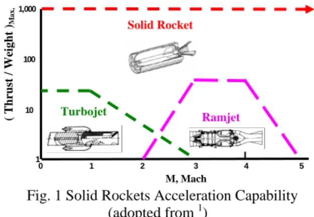
Fig. 1 Solid Rockets Acceleration Capability (adopted from
1)
SRM has the highest Thrust to Weight ratio, due to higher exit velocity, and its independence from free stream velocity, and the capability of higher mass flow rate
1). It might at first seem that the design of SRM with a relatively small number of design parameters would be an easily tractable problem yielding to standard optimization techniques. In practice, designing a SRM can be difficult because the
100
10 Ramjet
1 0 1 2 3
M, Mach ( Thrust / Weight )Max,
4 5
Turbojet
characteristics (e.g. grain geometry, bum rate etc.) all vary with respect to time. Sets of parameters producing the desired characteristics at one particular time may fail to produce an acceptable performance a short time later. The designer/engineer can therefore spend an inordinate amount of time searching for the ideal parameter set which works well for the entire burn time of the interceptor. An alternative to this process is the use of Genetic Algorithms (GA) that controls the design of each missile component simultaneously. With GA controlling the design optimization process the design engineer is able to make broad system-level goals such as minimize take- off mass and minimize miss distance and then turn the design optimization process completely over to the GA. This approach to missile system design frees engineers to improve their component level models (like propulsion) while letting the computer do what it does best: tirelessly trying thousands of designs while learning which designs work and which ones do not against the mission requirements and constraints.
Propulsion system design problem is posed to GA under the given conditions and constraints. The Mass Model of the GBI is derived from
2,3). KV weight and volume requirements
4,5)are specified in the problem definition before the optimization is computed.
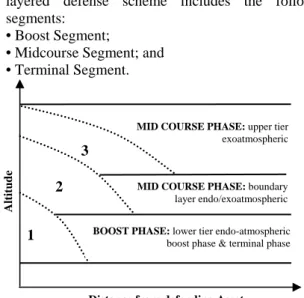
Principles of Ballistic Missile Defense – (BMD) The principle of BMD has various interpretations; the layered defense scheme includes the following segments:
• Boost Segment;
• Midcourse Segment; and
• Terminal Segment.
Fig. 2 Layered Defense [adopted from
6)] Boost Phase
The boost phase is initiated with rocket ignition just prior to liftoff and completed after burnout of the final stage of the ballistic missile. During this time frame, the ballistic missile accelerates to its maximum speed, missile velocity is relatively slow during this phase because the initial velocity is zero and the rocket engine’s propulsive force is opposed by the earth’s gravity. The discharge of hot propellant gasses makes the exhaust plume highly visible to infrared detectors at great ranges. Thrust is terminated at the end of boost phase. Older missile types, such as the SCUD,
No Dong 1 (ND-1), and the Chinese Surface-to- Surface Missile 2 (CSS-2) had an acceleration of 3g;
whereas newer missiles have an average acceleration of approximately 10g. ICBMs have a range capability in excess of 5000 kilometers and boost phase duration of approximately 240 seconds for rocket engines using liquid propellant and 180 seconds for solid propellant rocket engines
4). ICBMs exit the earth’s atmosphere by the end of boost phase whereas IRBMs only reach the periphery of the exo-atmosphere. Duration of boost phase, maximum altitude and downrange attained by the end of boost phase is dependent on various design parameters including the guidance law, propellant burn rate, acceleration, launch angle.
Table 1: Termination of Boost Phase
Missile Range (km)
Burnout Altitude (km)
Burnout Range (km)
500 20-40 25-75 1,000 45-70 40-100 2,000 70-130 75-150 3,000 100-170 125-250 10,000 175-220 425-475
Midcourse Phase
The midcourse phase en-compasses the longest segment of the trajectory, the weapon payload, which may be a unitary warhead, multiple re-entry vehicles, or submunitions, is deployed during this phase and follows an unpowered ballistic trajectory towards the intended target. The midcourse trajectory will take place in the exo-atmosphere for ICBMs and intermediate range ballistic missiles. Intercepting the weapon payload during the midcourse phase is complicated by the need to eliminate all submunitions or re-entry vehicles (RV), plus discriminating and excluding any countermeasures and booster debris.
Terminal Phase
The terminal phase is the ending segment of the missile’s flight trajectory. The weapon payload has amassed great speed by the start of this phase;
however, re-entry into the earth’s atmosphere will impart changes to the weapon’s velocity and trajectory.
Atmospheric drag ensures the weapon is separated from the debris field. Lastly, the weapon is capable of maneuvering to avoid interception during this phase.
Table 2: Trade offs between Intercept Phases
Phase Duration (min)
Defense Advantages
Defense Challenges
Boost 3 -5
Large defended areas Threat cannot deploy decoys
Short, unpredictable trajectory Basing proximity
Midcourse 20 -25
Predictable
"ballistic" trajectory Multiple intercept shots possible
Threat can deploy decoys
Sensor data fusion
Terminal 0.5 - 1
Re-entry mitigates decoys
Focused defense of key assets
Short intercept window
Small defended area
2
1
3
Distance from defending Asset
Altitude
MID COURSE PHASE: upper tier exoatmospheric
BOOST PHASE: lower tier endo-atmospheric boost phase & terminal phase MID COURSE PHASE: boundary layer endo/exoatmospheric
Design Architecture for Ballistic Missile Intercept When designing complex systems, particular attention must be paid to the chosen architecture. Architecting requires balancing characteristics and elements so they fit together in appropriate compromises to create good systems. One major domain for systems architecting is space operations. Conceptual Design Architecture (CDA) introduces the notion of design space exploration, which allows understanding the position of a particular architecture in the larger technical and economic context. A computer simulation captures the important elements of the design problem. In this process, high level design decisions are mapped to system performance, lifecycle cost and capacity. A simulation model gives an algorithmic representation of a system, reflecting system structure and behavior, which explicitly recognizes the passage of time, hence providing a means of analyzing the behavior of system over time
7).
The performance of the propulsion system (three SRMs) designed for the GBI is validated using a ballistic missile intercept scenario modeled in Matlab/SIMULINK. 3D model developed for both GBI and target with a boost phase acceleration profile that depends on total mass, propellant mass and the specific impulse in the gravity field. The RCS
8,9)and infrared radiation (IR) of the target structure is estimated as a function of the flight profile. GBI uses fused target location data provided by two ground based RF radar sensors
10)and two (LEO) IR sensors.
11)Monostatic RCS data of a three stage ICBM is used.
12). GBI carries the KV to an optimal position in space to allow it to complete the intercept.
//////////////////////////////////////////////////////////////////////////////
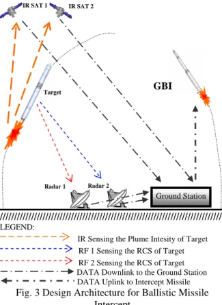
LEGEND:
IR Sensing the Plume Intesity of Target RF 1 Sensing the RCS of Target RF 2 Sensing the RCS of Target DATA Downlink to the Ground Station DATA Uplink to Intercept Missile
Fig. 3 Design Architecture for Ballistic Missile Intercept
The intercept scheme was constructed around the following scenario. An ICBM is launched from a given launch site. The target is tracked by two ground–based RF sensors and two space–based IR sensors. The target position data is transmitted to a fusion processor to calculate an accurate target position. The fused target position data is used to guide GBI. Though GBI is launched after a certain delay following the target launch and establishes collision geometry with the target, but for our preliminary design we have assumed zero delay. At a suitable distance, the KV is launched from the GBI to accomplish the intercept. The KV hits to kill the target, and the intercept is accomplished. Two important elements of the scenario are beyond the scope of this research. The first is the data fusion. The track data are fused here by using a simple averaging method.
The second is KV flight.
Kill Vehicle
The kill vehicle (KV) is the payload on the GBI, which imparts a destructive force on the threat missile.
KV effectiveness is gauged by the amount of miss distance at termination of the engagement. Successful interception is tantamount to complete destruction of the target and necessitates a negligible miss distance from the optimum aimpoint on the target warhead.
KV incorporates a guidance system to reduce the miss distance to an amount suitable for complete destruction of target. If the target is acquired at a long range then the divert capability can be used early in the mission to remove a relatively large initial miss distance with an initial lateral delta velocity that is integrated over the remainder of the mission. KVs for boost phase interception have not been fully implemented to date; however, similar systems for ground-based midcourse defense have been designed and tested. Most of the forward momentum required by the KV is provided by the GBI booster’s burnout velocity. For a conservative design, the GBI is allowed to fly until it hits the target instead of launching the KV. The KV size and weight requirements are derived from
4, 5, 13)Conceptual Design Analysis of GBI
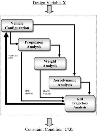
Conceptual designs cannot be conducted without the cooperation of numerous disciplines, including several analysis technologies: aerodynamic analysis, propulsion analysis, structural analysis, trajectory analysis, heating analysis, controls analysis, cost analysis, operations analysis, and so on. A typical duration of conceptual design activity is 3~9 months.
Based on mission requirements, an initial baseline from existing systems with similar propulsion is established. It is used as a starting point to expedite the design convergence. Propulsion sizing includes providing sufficient propellant or fuel to meet the range and time to target requirements. The next step is to estimate the weight of the missile with its propulsion. Much of this activity is focused on structural design which is sensitive to changes in
IR SAT 1 IR SAT 2
Radar 2
Ground Station Target
GBI
Radar 1
flight performance. Following the weight sizing, the flight trajectories are computed. The range, terminal velocity, maneuverability, and other flight performance parameters are then compared with mission flight performance requirements. If the missile does not meet the mission requirements, it is resized and re-iterated
1).
The approach used here in this study is simpler and of lower fidelity than the latest sophisticated computation methods, but needs lesser computation time so it is useful enough for preliminary conceptual design. The preliminary or conceptual design deals with a basic system configuration (layout and dimensions), an estimate of the mass and an estimate of the expected performance i.e. thrust level and propellant usage. etc
Design Variable X
Constraint Condition, C(X)
Fig. 4 Conceptual Design Analysis Approach
The baseline design here is that all three stages are made of sequentially stacked SRMs. The payload (Kill Vehicle) is enclosed in a fairing whose shape is known beforehand. Each rocket motor has ellipsoidal dome ends. The KV weight and volume requirements are specified in the problem definition before the optimization is computed. Though the number of stages should also be one of the design variables, however, in this paper it is fixed as three. Propulsion analysis describes important parameters like thrust, burn time, mass flow rate and nozzle parameters.
Weight Analysis
Minimizing vehicle empty weight is important for any vehicle concept and critical for any missile. This will require the integration of lightweight composite materials into the vehicle airframe and subsystems.
Modern composite materials have higher strength and stiffness than standard metals, which can significantly reduce overall vehicle structural weight. For example, per-unit-weight graphite epoxy is five times stronger than aluminum alloy, the material the space shuttle airframe is composed of. According to some analyses, advanced composite materials and lightweight metal alloys may permit launch vehicle structure weight to be reduced by up to 35 percent. Weight analysis mainly gives the expression for structure mass including components like motor casing, dome ends, nozzle, etc.
Mass Model of GBI
The take-off mass m
01of a multistage missile/launch vehicle is written as
2):
Vehicle
∑
=+ + + + + +
=
ni
fsi fei asi svi sti gni
KV
m m m m m m
m m
1
01
( )
where m
KV= m
wh+ m
es+ m
DAC1
1 (1
oi oi
i gni ki sti
m m
N K μ
+α
= − − + )
(1)
C
in i gni ki stiKV o
u K N m m
1 1
)]
1 ( 1
[
=
+
−
−
=
α
m
KVis known by design mission. Skirt mass ratio N
i, and Propellant reserve coefficient K
gni, have small dispersions which can be selected from statistical data
3, 14, 15, 16, 17, 18)
. Relative mass coefficient of effective grain to m
01oi e gni
ki
m
u = m (2)
is function of range or burnout velocity. It is a design parameter which should be optimized. Structure mass fraction α
stiis the main problem for designing a multistage SBM. It is dependent upon structural material, grain shape, as well as the parameters of internal ballistics of SRM.
Fig. 5 Typical SRM Configuration
Propulsion Analysis
Weight Analysis
Aerodynamic Analysis
GBI Trajectory
VEHICLE SIZE
STAGE WEIGHT TIME
Analysis
THRUST
Igniter
Nozzle
Chamber Case Grain
Fig. 6: Mass Model of SRM
Mass Model of SRM
This structure mass fraction is shown below:
cc cl n in
sti
gni
m m m m
α = + m + +
(3) where
1 3
2
c cc
cc gni i
i
m fp
ρ π λ
Dσ
⎛ ⎞
= ⎜⎝ + ⎟⎠
(4)
( 1 )
3cl
2
cl gni im = π ρ λ − ε D
(5)
. 3
sin 1
av
s gi i gni n c c n e
n g
o c n t
k u R T A
m p A
ρ ρ α
β λ
⎛ ⎞
= Γ ⎜ ⎝ − ⎟ ⎠
niD
i(6) (7)
( 2 )
3cc
in in gni in i
m = K + πλ ρ D
The basic principles of SRM case design and analysis are essentially the same as those of the plate-and-shell approach that has been used for many years in the design and analysis of boiler-type, pressure- containing structures and aircraft-type structures.
Grain design has always been a vital and integral part of SRM design. Basing on the design objectives set by the system designer, the SRM designer has many options available for selecting the Grain configuration. Many of the available configurations may fulfill the required parameters of volumetric loading fraction, web fraction & Length to diameter ratios and produce internal ballistic results that may be in accordance to the design objectives. However, for any given set of design objectives, it is deemed necessary that best possible configuration be selected, designed and optimized. Hence optimal results of all applicable configurations are vital to be attained in order to compare and finalize the design that will produce most efficient performance. The design and performance of SRM and Grains is discussed in detail in
19,20and
21,22)respectively.
However in this analysis, we have not restricted to a particular shape of grain at conceptual design level, rather a variable k
siis used to represent the burning surface area S
riof grain as a function of grain length L
iand diameter D
i. The chamber Pressure (P
c) is an important design variable which has an affect on the motor specific impulse. Increasing the P
cwill reduce the losses at the nozzle exit and increase the specific impulse. The P
c, however, also has effects on the burning rate of the propellant, combustion stability, size of expansion nozzle and the thickness of the casing materials to with-stand the pressure stresses.
Forward and aft skirts (thrust skirt) Forward and aft closures Cylindrical section (shell)
Burning surface area of the propellant grain mainly dictates the performance of propulsion system in a SRM.
3
gni
4
gni i gni im = π ρ ψ λ D
(8)
( 4 )
1 3i gni ki oi gn i gni
D = K μ m πρ ψ λ
(9) The grain mass consumed rate is
2 i gni si i gni ri i
gni gni
u S u K D
m
•= ρ = ρ λ (10) Finally, the total mass of the ith stage SRM should be
igi TVci cablei nozzlei casei
sti
m m m m m
m = + + + + (11)
Propulsion Analysis
In order to calculate average specific impulse I
sp, the process of a real SRM should be simplified and abstracted to be an ideal SRM. Some assumptions are needed:
• The grain is burned perfectly in combustion chamber and its gas is ideal gas, the “specific heat ratio” of the gas keeps constant during expansion.
• Average expansion, between the gas phase and condensed phase there are no velocity-lag and temperature-lag.
• One dimension flow, the exhaust is parallel to the axis of SRM.
• Without viscosity, between gas flow and internal wall, no friction loss and heat dispersion loss.
Under the same conditions, the specific impulse of and ideal SRM, which is named “theoretic impulse”, is easy to set up the relationship of thrust (F), specific impulse w.r.t. design parameters. It is recommended to use mass flow rate and specific impulse for calculation of thrust using following relations.
3)( )
1
1 1
o
sp gi o h e
F = I m
•+ p − p A
(12)
2..
vac gi
N sp h ei
F = I m
•− p A
(13)
1
01 1 1
2
1 1
v e c c o
sp sp a
c o sp e
p R T p
I I p g I p
γ γ
⎛ ⎞
−= − ⎜ ⎝ ⎟ ⎠
(14)
1 2
vac a e c c
sp sp a
c o sp
p R T
I I p g I
γ γ
⎛ ⎞
−= + ⎜ ⎝ ⎟ ⎠
(15)
Attachment joint Thermal insulation/liner
Conic shell Attachment flange Thermal insulation/liner Thrust vector control system
Grain
Coating
Chamber
Nozzle
Igniter
Grain
. 2
19.4 0.76 0.003 70 25
a red std 2
sp sp c c e e
I = I + + p − p − p + p
2
(16)
( )
. 2
1 4.3 0.17 0.009 10
red std std
sp sp
I = I ⎡ ⎣ − + Al + Al
−⎤ ⎦ (17) The working time t
ki, grain mass consumption rate m′
gni, nozzle throat area A
tand expansion ratio ε, of i
thstage are also calculated in propulsion analysis module:
4
.ki i i gi s gi
t = πψ D u k
(18)
2 gni gn gi s gi. gni i
m
•= ρ u k λ D
(19)
2
t c c gn gi s gi gni. i c
A = R T ρ u k λ D Γ p
(20)
1
2 11
e e e
o c c
t
A p p
p p
A
γ
γ
γ
ε γ
⎡ −⎤
⎛ ⎞ ⎢ ⎛ ⎞ ⎥
= = Γ ⎜⎝ ⎟⎠ − ⎢⎣ −⎜⎝ ⎟⎠ ⎥
1 γ
⎦
(21)
( ) 2 12( 11)
o
γ
γ γ
γ +Γ = +
−(22)
Aerodynamic Analysis
This analysis involves estimating the vehicles’
aerodynamic properties in the different flow field regions that it encounters during atmospheric flight, which ranges from subsonic to hypersonic speeds.
The aerodynamic analysis incorporates USAF Missile DATCOM 1997 (digital). It is capable of quickly and economically estimating the aerodynamics of wide variety of design configuration, and it has the predictive accuracy suitable for conceptual designs.
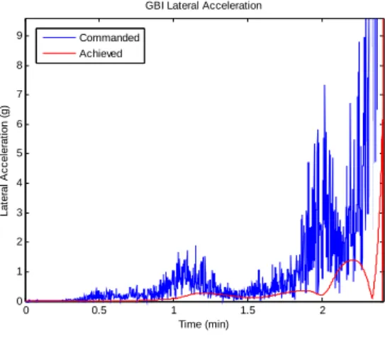
Intercept Trajectory Analysis
The next disciplinary design analysis is Interceptor performance analysis. When the concern is intercontinental ranges, the flat Earth approximation with a constant gravitational acceleration is no longer valid. The direction of the weight vector is towards the Earth’s center (round Earth model), and the change in the gravitational acceleration (m/s
2) is modeled as
23). The proportional navigation in 3D was implemented. The missile lateral acceleration and the missile lateral divert results are in accord with
24)as shown in Fig. It can be concluded that both results are reasonable and can be achieved by the missile flight control system .
Design Variables
Finally, we can see that the take-off mass of a missile is
m
01=m
01(n, m
KV, N
i, K
gni, μ
ki, α
sti) (i=1,2,…,n) where n is the number of stages.
) , , , , , , ,
( i ci gni i ei ti ki oi
gni sti
sti sti D p d d t I
m
m α λ ε
α = =
And
εi=εi(Ati,Aei)) , , , , , , (
) , , , (
) , (
) , , , (
) , , , , , , , , (
) , , , , , , (
ti ei ci ei i ci ci oi oi
i gni i gn gni gni
ai gni oi oi
si i i i ki ki
i ei ci i si i gni ci ci ei ei
ci i si i gni ci ci ti ti
A A p p T R I I
D m
m
I m I I
k u D t t
p p D k u T R A A
p D k u T R A A
γ λ ψ ρ ψ
γ ρ
ρ
=
=
=
=
=
=
With the purpose of simplification and some variables being variables being not independent, the following expression includes only independent variables:
m
01=m
01(n, μ
ki, p
ci, p
ei, λ
gni, k
si, u
i) (i=1,2,…,n) Introducing
ki i μki
χ =μ +1
(23) χ
istands for the mass ration of two adjacent stage missiles. Now, the take-off mass equation can be written as
m
01=m
01(n, μ
k1, χ
i-1, p
ci, p
ei, λ
gni, k
si, u
i) (i=1,2,…,n) Given a fixed m
KV, these independent design
parameters (μ
k1, χ
i, p
ci, p
ei, λ
gni, k
si, u
i) can exclusively determine the mass, geometric size, performance data of GBI. Different combinations of the values of these parameters can also satisfy the same performance, but the corresponding take-off mass and geometric sizes are also different. So, the optimization is required to get an optimum configuration.
Design Objective
SRM design is constrained by physical and/or performance requirements that limit the available optimization variables. The optimal design is one that minimizes system weight while operating within all these constraints and meeting all other performance objectives
25, 26). For the present effort, the design objective is to minimize the Initial Take Off Mass (Mg) of the interceptor missile under the design and mission constraints. In doing so, we try to configure an optimum propulsion system for GBI missile to achieve our goal i.e. effective intercept of the target.
Design Constraints
Several design constraints were posed on the design problem. Some of these constraints had both a lower bound (LB) and upper bound (UB), while others had only one constraint. Since the constraints varied notably in magnitude they were normalized.
0 1
0 1
⎥ ≤
⎦
⎢ ⎤
⎣
⎡ −
−
≤
−
LB UB
g g g g
(24)
Where g is the constraint value, g
UBis the upper
bound on the constraint and g
LBis the lower bound on
the constraint.
For the present effort, the design objective is to minimize the Initial Take Off Mass (kg) of the GBI under the constraints of miss distance (m), intercept time (min), lateral divert (m/sec), velocity at intercept, stage configuration requirements etc.
Some obvious checks were used to keep the GA from expending computational resources for designs that were not practical. Checks were made as follows:
As the body diameter helps to define the body geometry, the outer motor case radius cannot exceed body radius, SRM grain length cannot exceed body length. Nozzle exit diameters are constrained to be less than stage diameters. Based on the specified payload (Kill Vehicle), electronic weights, densities, and SRM size, the total volume of the missile must be able to house these components.
The overall structure of the system would have to be extremely strong to survive the high g-loads. It is appropriate therefore to specify a maximum number of g’s that should not be exceeded and any solutions that violate the g-limit are stopped at the point of violation.
For this study, a 10 g-limit was used.
If any of these conflicts occur, the GA is set to send back extremely poor performance values in each goal area so that it will learn not to try these designs in the future. We have considered only continuous design variables, while considering discrete variables as input.
In doing so, we try to configure an optimum propulsion system for GBI missile to achieve our goal.
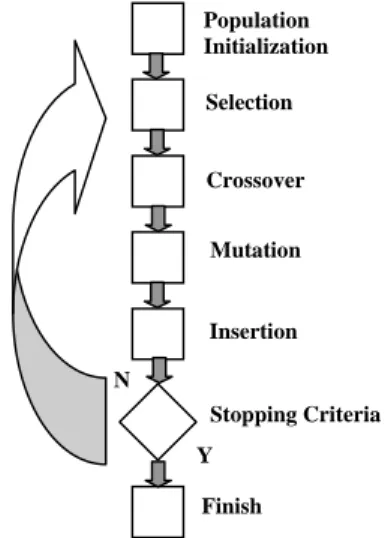
Genetic Algorithms
GAs are capable of examining historical data from previous design attempts to look for patterns in the input parameters which produce favorable output.
Calculus-based optimization (e.g. gradient descent methods) schemes use sensitivity derivatives in the immediate vicinity of the current solution and can therefore easily fall into local optima from which they cannot recover. To avoid these local optima and to increase the odds of obtaining an acceptable solution these calculus-based methods require a reasonable starting solution. GA approach is used in this work and it uses neither sensitivity derivatives nor a reasonable starting solution and yet proves to be a powerful optimization tool.
GA is the controlling routine in Fig. 6, which calls the propulsion and trajectory performance code. GA passes down the design parameters to performance and sizing code which gives mass and mass flow rate to Interceptor trajectory simulation which passes back a measure of how well the design performed in terms of minimum take-off mass of GBI achieved. Linking the sizing code and trajectory simulation code to the GA was done in modular fashion so that other modules could be later substituted for the ones used in the study.
Using GA as a non-calculus, Direct Search based global search method allows optimization-like techniques to be applied in the conceptual phase of design, which traditionally has been dominated by qualitative or subjective decision making. Features of
the GA provide several advantages for conceptual design including: the ability to combine discrete, integer and continuous variables, the population- based search, no requirement for an initial design, and the ability to address non-convex, multimodal and discontinuous functions.
Population Initialization
Selection
Crossover
Mutation
Insertion
Stopping Criteria
Finish Y N
Fig.7 The Simple Genetic Algorithm
The elite solution from GA is passed on to (Sequential Quadratic Programming) SQP as near optimal guess. The SQP then performs local convergence to identify the minimum mass of the GBI. It was found that the reduction in mass due to SQP was about 2kg.
20 25 30 35 40 45 50
0 1000 2000 3000 4000
Function Count
Objective Function: Mass (Mg)
GA SQP
Fig. 8 Performance of Genetic Algorithm
Though, the optimization results are to be
considered as preliminary (proof-of-concept) only,
but they can be compared to existing systems
14)and
used for future design of GBIs. The GA optimized
performance and results for the GBI are good enough
for preliminary conceptual design. The speed with
which they can be achieved allows designer to include
more variables in Multi-Disciplinary Design
Optimization loops.
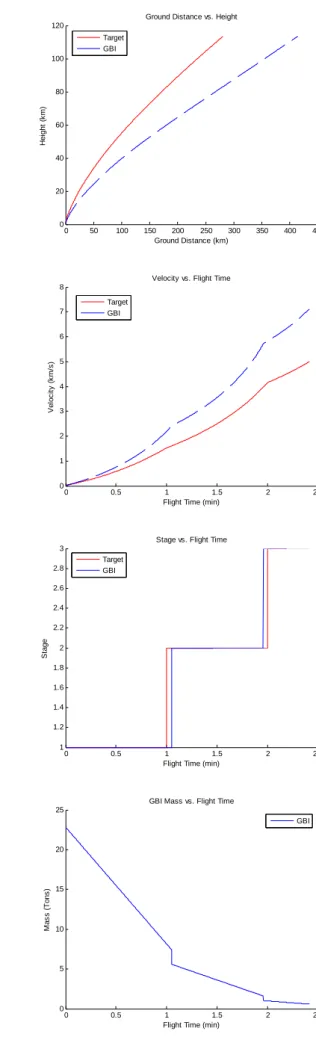
Optimization Results
Table 3 Optimum Value of Design Variables
Design
Variable Symbol Units LB UB GA Optimized
GA + SQP Optimized 1 μk1 0.6 0.7 0.601598 0.671893 2 μk2 /μk1 1 1.04 1.012332 1.035063 3 μk3 /μk2 1 1.08 1.001158 1.001028 4 D1 m 1.2 1.8 1.349532 1.530093 5 D2 /D1 0.7 0.95 0.828568 0.70296 6 D3 /D2 0.7 0.95 0.867551 0.940022 7 Pc1 bar 50 70 50.0570 68.738 8 Pc2 bar 40 60 41.3045 59.1446 9 Pc3 bar 30 50 30.8779 30.103 10 Pe1 bar 0.5 0.9 0.600908 0.750886 11 Pe2 bar 0.15 0.325 0.195824 0.158939 12 Pe3 bar 0.1 0.25 0.187561 0.20444 13 u1 mm/sec 5 11 8.04517 10.12838 14 u2 mm/sec 5 10 8.66379 9.105 15 u3 mm/sec 5 9 5.48229 7.258 16 ks1 1.5 2.3 2.270976 1.69208 17 ks2 1.5 2.3 1.519516 1.534257 18 ks3 1.5 2.3 2.207254 2.000536
Fig. 9 Optimized Configuration
0 50 100 150 200 250 300 350 400 450
0 20 40 60 80 100 120
Ground Distance vs. Height
Ground Distance (km)
Height (km)
Target GBI
0 0.5 1 1.5 2 2.5
0 1 2 3 4 5 6 7 8
Velocity vs. Flight Time
Flight Time (min)
Velocity (km/s)
Target GBI
0 0.5 1 1.5 2 2.5
1 1.2 1.4 1.6 1.8 2 2.2 2.4 2.6 2.8 3
Stage vs. Flight Time
Flight Time (min)
Stage
Target GBI
_________ KV Mass kg 200
___ __Stage III
Mass kg 951 Propellant Mass kg 801 Mass Flow Rate kg/sec 16.27382 Thrust kN 43.78493 Isp sec 269.1vac
Stage II
Mass kg 4572
Propellant Mass kg 3980 Mass Flow Rate kg/sec. 73.1209
Thrust kN 206.296
Isp sec 282.1vac
0 0.5 1 1.5 2 2.5
0 5 10 15 20 25
GBI Mass vs. Flight Time
Flight Time (min)
Mass (Tons)
GBI
__Stage I
Mass kg 17251
Propellant Mass kg 15436 Mass Flow Rate kg/sec. 244.5893
Thrust kN 596.1638
Isp sec 243.7
0 0.5 1 1.5 2 2.5 0
100 200 300 400 500 600
GBI-Target Distance
Time (min)
Distance (km)
0 0.5 1 1.5 2
0 1 2 3 4 5 6 7 8 9 10 11
GBI-Target Closure Velocity
Time (min)
Vc (km/s)
0 0.5 1 1.5 2 2.5
0 50 100 150 200 250 300 350 400
GBI Lateral Divert
Time (min)
Lateral Divert (m/s)
0 0.5 1 1.5 2 2.5
0 1 2 3 4 5 6
Target Maneuver
Time (min)
Maneuver (g)
0 0.5 1 1.5 2
0 1 2 3 4 5 6 7 8 9
GBI Lateral Acceleration
Time (min)
Lateral Acceleration (g)
Commanded Achieved