• 검색 결과가 없습니다.

Effect of TiO<sub>2</sub> Nanotube Length on Photocatalytic Activity with Different Light Intensities: Cr(VI) Reduction and Hydrogen Production

N/A
N/A
Protected

Academic year: 2021

Share "Effect of TiO<sub>2</sub> Nanotube Length on Photocatalytic Activity with Different Light Intensities: Cr(VI) Reduction and Hydrogen Production"

Copied!
11
0
0

로드 중.... (전체 텍스트 보기)

전체 글

(1)

광량 및 TiO

2

나노튜브 길이별 광활성 연구: Cr(VI)환원 및 수소제조

주현규*, 심은정*, 이재민**, 윤재경*

*한국에너지기술연구원 수소에너지센터, **연세대학교 화공생명공학과

Effect of TiO

2

Nanotube Length on Photocatalytic Activity with Different Light Intensities: Cr(VI) Reduction and

Hydrogen Production

HYUNKU JOO*, EUNJUNG SHIM*, JAEMIN LEE**, JAEKYUNG YOON*

*Hydrogen Energy Research Center, Korea Institute of Energy Research 71-2 Jang-dong, Yusong-gu, Daejeon 305-343, Korea

**Dept. of Chemical and Biomolecular. Engr., Yonsei Univ., 262 Seongsanno, Seodaemun-gu, Seoul 120-749, Korea

ABSTRACT

Anodized tubular TiO
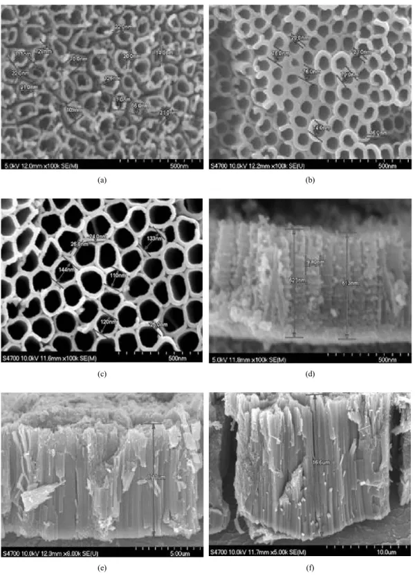
2

electrodes (ATTEs) with three noticeably different lengths are prepared to determine their optimum length for the photo-driven activity in the reaction of Cr(VI) reduction and hydrogen evolution. The ATTEs with ethylene glycol have longer TiO
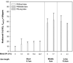
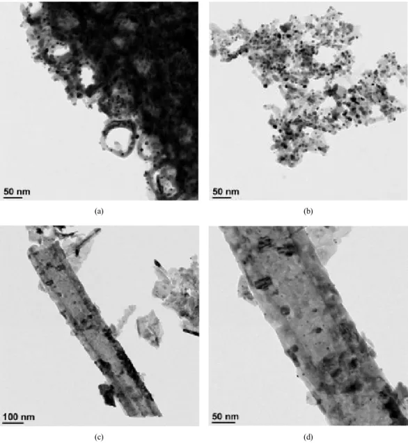
2

tubes (7-15.6 μm) than those with hydrfluoric acid (0.6-0.8 μm). These samples, which differ only in the length of the tubes, with a wall thickness of ca. 20 nm, consist mainly of an anatase crystalline phase after heat treatment at 650℃, since the anatase crystallites at the tube walls do not undergo transformation into rutile phase, due to the constraints imposed by the wall thickness. Among them, the medium size (ca. 8 μm) tubes provide the optimum conditions, irrespective of the light intensity, which is explained in terms of the correlation between the amount of photons and the adsorbed electron acceptors and their location. Photocatalytic Cr(VI) reduction leads to ca. 60%

reduction of Cr(VI) even under 1 sun irradiation with the medium-sized anodized TiO

2

tubes, but only ca.

20% with the short- and long-sized tubes. For hydrogen evolution, tubes longer than 8 μm do not exhibit better performance with any light intensity.

KEY WORDS : Anodization(양극산화), Immobilized titania(고정화 티타니아), Photoanode(광어노드), Ecomaterials(친환경재료), Cr(VI) reduction(6가크롬 환원), Hydrogen(수소)

Corresponding author : [email protected]

[

접수일

: 2011.5.16

수정일

: 2011.8.11

게재확정일

: 2011.8.22 ]

(2)

1. Introduction

The conversion of harmful chemicals into non- toxic substances and hydrogen production by water splitting using photocatalysis have been of interest since the early 1970s when Honda and Fujishima first performed their pioneering work using solar light and UV-absorbing TiO

21)

. This interest is, of course, owing to the environmental problems and the depletion of fossil fuels and, hence, photocatalysis continues to attract the attention of researchers because, among the various renewable energy sources, the sun is an inherently abundant and clean energy source

2)

. Apart from the light source, the semi-conductor which converts light into elec- trical or chemical energy is essential for the photo- electrochemical (PEC) reaction to happen. Therefore, photocatalysts immobilized on conducting substrates have been used as both the key part of light-driven purification systems and the photoanode of the PEC systems, since the conventional slurry or coated type system presents a problem concerning the recovery or stability of the photocatalyst. Among semiconductor photocatalysts used as photoanodes, titanium dioxide (TiO

2

) has received tremendous interest in research works of photocatalysis tech- nology and a review of works including metal oxides and nonoxides photocatalysts for hydrogen gen- eration, in particular, has been published recently

3)

. However, the photocatalytic process with semicon- ductor particulate systems has been simultaneously criticized as being uneconomical compared to other oxidative treatment systems due to its inherently low efficiency and the limitations resulting from the necessity for a novel material, an appropriate light source, and immobilization, which may increase the overall energy costs

4)

. Therefore, for the im- provement of the conversion efficiency obtained with solar energy, it is essential to design an

energetically coordinated, stably operated, and eco- nomically feasible photocatalyst-immobilized matrix.

Over the past few decades, photoanodes covered with TiO

2

-based films have been prepared using techniques such as anodization

5-10)

and sputtering

11)

. Meanwhile, as the materials, TiO

2

nanotube arrays prepared by the anodization of Ti foil have attracted the particular interest of the authors as a light-sensitizing material for photocatalytic puri- fication and as the photoanode and cathodic sub- strates for enzyme and metal species

12-19)

. The two major issues concerning the light penetration, electron migration and photohole capture associated with the anodized TiO

2

tube arrays are the enhancement of the visible-light sensitization and the increase in the amount of the photocatalyst: this requires the optimization of the length of the tubes and thickness of the tube wall. For this purpose, in this study, we examine the correlation between the length of the tubes and the light intensity in the Cr(VI) reduction and hydrogen evolution reactions.

Chromium occurs in two common oxidation states

in nature, Cr(III) and Cr(VI), and, among them, Cr

(VI) is a frequent contaminant in water, arising

from industrial processes such as electroplating,

leather tanning and paint-making, and it has been

regulated in many countries due to its acute

toxicity, carcinogenic action and high mobility in

water. Therefore, the reduction of Cr(VI) to Cr

(III) is highly desirable in order to reduce its

toxicity and contain the mobility of the chromium

ions. After its reduction to Cr(III), it can be

separated by several procedures, which involve

its precipitation in neutral or alkaline solution in

the form of Cr(OH)

320,21)

. For this reason, pho-

tocatalytic Cr(VI) reduction, as well as hydrogen

evolution, was selected as one of the designated

reactions for the measurement of the activity of,

(3)

and as a possible application of, the ATTEs.

2. Experimental

2.1 Materials and sample preparation Titanium foil (Ti, 99.6 wt.% purity, thickness 0.25 mm, Goodfellow, England) was cut into pieces (2 cm × 4 cm) and subjected to poten- tiostatic anodization in a two-electrode electrochemical cell (100 ml of an electrolyte) connected to a DC power supply using a platinum counter electrode with magnetic agitation, after which the samples were annealed in an oxygen atmosphere (400 ml・

min

-1

) at 450 or 650℃ for 2 hr for Cr reduction and H

2

evolution, respectively. The two different electrolytes used were i) 0.5 vol.% hydrofluoric (HF) acid at 5℃ (48-51 vol.%, DC Chemical) for 45min at 20 V for the short TiO

2

tubes (‘electrolyte i’) and ii) 0.3M NH

4

F (99.99 vol.%, Sigma-Aldrich) + 2 vol.% H

2

O + ethylene glycol (EG 99.8 vol.%, Sigma-Aldrich) at 0.1 A for 1.5 hr or 3 hr for the medium and long TiO

2

tubes (‘electrolyte ii’). The resulting electrode is called an “anodized tubular TiO

2

electrode” or “ATTE” and used as a photo- responsive material for Cr(VI) reduction and as a photoanode in an enzymatic hydrogen evolution system. A detailed explanation of the role of each component of the anodizing solution is available in the literatures

5-9)

.

Potassium dichromate (K

2

Cr

2

O

7

, 99.5 wt.%, Orien- tal chemicalindustries, Korea) was used to make the initial Cr(VI) solution. Chloroplatinic acid hex- ahydrate (H

2

PtCl

6

6H

2

O, 37.5 wt.% as platinum, Sigma-Aldrich) was used as a precursor for platinum (Pt hereafter) deposition. Pt deposition was conducted at a fixed current of 0.01 A for 5 min in a two- electrode electrochemical cell using a potentiostat (G300 with PHE200 software, GAMRY Instruments

Electrochemistry, PA, USA) with platinum electrodes as both the counter and reference electrodes and the prepared anodized sample as the working electrode. The Pt-treated samples were washed with distilled water in order to remove any chlorine.

Then, the samples were dried at room temperature and annealed at 500℃ for 2 hr in 400 ml・min

-1

of reducing gas (10% H

2

in argon balance) for the reduction of the Pt ions.

The area of the illuminated working electrode (prepared ATTE) and the cathode for the im- mobilization of hydrogenase was 1 cm × 1 cm (20 V at 5℃ for 45 min, then heat-treated at 650℃

under O

2

flow rate of 400 ml・min

-1

). Potassium hydroxide solution (1.0 M) was prepared from KOH pellets (99.99 wt.%, Sigma-Aldrich) and used as the electrolyte in both compartments for hydrogen evolution. Purified hydrogenase (from Pyrococcus furiosus, ‘Pfu’ hereafter) was supplied by Prof.

Adams at the University of Georgia and this enzyme is known to be remarkably resistant to inactivation by heat and chemical reagents

22)

. For the immobilization of the enzyme on the ATTE, aryl azide crosslinking reagent (Sulfo-SDA, spacer arm 3.9Å, PIERCE Biotechnology, USA) was used.

The details concerning the immobilization of the enzyme are described in the literatures

13-16)

.

2.2 Apparatus and analysis

The experiments for Cr(VI) reduction were con- ducted in a photocatalytic reactor. The volume of the reactor was 150 ml and it contained an aqueous solution whose initial concentration of Cr(VI) and pH were adjusted. It is known from a previous study

12)

that the surface charges of all ATTEs are positive at pH=3 and become more negative with increasing pH and that Cr(VI) ions (Cr

2

O

72-

) are

the predominant species at medium to low pH

(4)

(a) (b)

(c) (d)

(e) (f)

Fig. 1 SEM images of the selected samples; (a)~(c) top views and (d)~(f) side views for the short, medium and long

anodized TiO

2

tubes, respectively

(5)

values. Therefore, the experiments for Cr(VI) re- duction were conducted at an initial concentration of 10 ppm at pH 3 with HCl. The outside of the reactor was water-jacketed to keep the reaction temperature constant. Prior to Cr(VI) reduction, cyclic voltammetry was performed to measure the photocurrent to evaluate the electrochemical behavior of the ATTEs with a platinum coil as the counter electrode and Ag|AgCl (saturated in 3.0M KCl) as the reference electrode. For hydrogen evolution, the experiments were conducted in a two-com- partment reactor which was separated by a nanofiltration (NF) membrane and a solar cell. A detailed description of the geometry and procedure was reported previously

13-19)

. The light sources used were a 1000 W Xe lamp (Oriel, USA), which was filtered through a 10-cm IR water filter and a 300 W solar simulator. The irradiated light intensities were ca. 1803.4 mW・cm

-2

and ca. 1.801.3 mW・cm

-2

(at the range of 300~400 nm measured with UM-10 and UM-360 portable radiometers, from Minolta Co., Japan). A reference cell (91150V, Oriel, USA) was also used for calibration with 1 sun irradiation. The concentration of Cr(VI) was analyzed colorimetrically using UV/Vis spectroscopy (SCINCO, S-3150, Korea). In this analysis, the 1, 5-dipheny- lcarbarzide method was used

23,24)

. The hydrogen produced was analyzed by a gas chromatograph with a thermal conductivity detector (TCD at 260℃, oven at 40℃). The column used in the system was a molecular sieve 5 A (Supelco, USA). The structure and morphological characterizations were conducted using scanning election microscopy (SEM, Hitachi S-4700, Japan) and transmission electron microscopy (TEM, EM912 Omega, Carl Zeiss, Germany).

3. Results and Discussion

The color of the as-anodized samples with

‘electrolyte i’ was gray and changed to dark gray after the heat-treatment, while that of the as- anodized samples with ‘electrolyte ii’ was dark green and changed to blue after the heat-treatment.

There was no noticeable hump in the region of 400-540 nm in the UV-Vis spectra of the samples, as reported by Varghese et al., in which heat- treatment at 450℃ under nitrogen was performed

25)

. This discrepancy may arise from the environment used for the heat-treatment. The morphology of the ATTEs prepared in this study was not no- ticeably different, except for their length (Fig. 1 (a)~(c)). The diameter and wall thickness of the TiO

2

nanotubular arrays are in the range of 140 nm and 20 nm, respectively (short, medium and long tubes in Fig. 1(a), (b) and (c), respectively), and these arrays were vertically oriented, compact and straight (short, medium and long tubes in Fig. 1 (d), (e) and (f), respectively). The hole dif- fusion length in titania is ca. 10 nm, while the electron diffusion length is ca. 10 μm

24)

. Therefore, one-dimensional TiO

2

nanotubes with 10nm of one half the wall thickness of the nanotube are essential for charge generation and transport. The samples prepared with EG contained very straight TiO

2

nanotubes standing on the Ti foil whose diameter was close to 10 nm.

Fig. 2 shows selected TEM images (surface view) of the prepared short and long ATTEs. The set of images at the top (a and b) correspond to the sample prepared in ‘electrolyte i’ and those at the bottom (c and d) to the sample prepared in

‘electrolyte ii’. Well dispersed Pt particles less than 10 nm in diameter were clearly seen in all of the images.

This supports the explanation given in the

schematic drawing in Fig. 3(c). The density of

the deposited Pt particles is different in each case,

due to difference in the length of the tubes. Their

(6)

(a) (b)

(c) (d)

Fig. 2 HR-TEM images of the Pt-deposited selected samples; (a) and (b) for short anodized TiO

2

tubes, (c) and (d) for long anodized TiO

2

tubes

X-ray diffraction patterns were reported in a previous article

26)

, where all of the as-anodized samples were found to be amorphous, while heat- treatment in dry O

2

led to the predominant formation of anatase phase at 450℃, while rutile phase appeared at 650℃ when EG was added to the anodizing electrolyte (electrolyte ii). Anodization

with ‘electrolyte i’ led to the growth of the same rutile phase after heat-treatment at temperatures of 550℃ and above.

As shown in Fig. 3, there must be a relation between the light intensity and length of the tubes.

Fig. 3(a) depicts the relative degree of Cr(VI)

reduction in terms of the tube length when the

(7)

(a)

(b)

(c)

Fig. 3 Schematic represenation of the effect of the length of the TiO

2

tubes and light intensity on the reactivity; (a) for low intensity, (b) for high intensity and (c) for metal deposited TiO

2

tubes at a fixed light intensity

Fig. 4 Cr(VI) reduction with different anodized TiO

2

tubes under 1 sun irradiation ([Cr(VI)]O = 10 ppm at pH 3)

intensity of irradiated light is low (L1). A short tube (less than 1 μm) can be completely irradiated

even with a low light intensity, while most of the photons cannot reach the bottom (barrier layer) of the long tubes (ca. 15 μm). However, the optimum amount of photons is irradiated on the medium length tubes. For this reason, the surface area is the limiting factor for the short tubes, while the light intensity is the limiting factor for the long tubes. In both cases, there are too many Cr(VI) molecules far away from the surface of the short tubes in the radial direction of the tube, while the adsorbed Cr(VI) molecules on the non-irradiated surface of the long tubes obviously cannot participate in the reaction, resulting in low efficiency. However, the medium length tubes provide sufficient surface area for the Cr(VI) molecules at a certain con- centration to be adsorbed and for enough photons to irradiate them, resulting in the highest efficiency among the three cases.

The experimental data on Cr(VI) reduction are shown in Fig. 4, where the percentage reductions of Cr(VI) were 16.4±6.0, 52.9±0.3 and 18.5±1.0%

for the short, medium and long tubes, respectively.

This result is well matched with the hypothesis

mentioned above. At the higher intensity (L2) in

(8)

Fig. 5 Cr(VI) reduction with different anodized TiO

2

tubes under high intensity ([Cr(VI)]

O

= 10 ppm at pH 3)

Fig. 6 Hydrogen evolution rate with anodized TiO

2

tubes under different light intensities

Fig. 3(b), the only difference in the case of the long tubes is the higher efficiency compared to that at the lower intensity. This is because in the other two cases, i.e. the short and medium length tubes, there is no advantage in using a higher intensity, whereas the higher surface area of the long tubes allows more radiation to act on the adsorption sites in order for the Cr(VI) molecules to be reduced to Cr(III). Accordingly, the percentage reductions of Cr(VI) were 9.4±0.9, 57.5±8.3 and 60.7±11.3% for the short, medium and long tubes, respectively, as shown in Fig. 5. This is also coincident with the explanation in Fig. 3(b) above.

Fig. 3(c) depicts the case where metal is deposited on the surface of some of the tubes. In the case of the short and medium length tubes, the deposition of Pt slightly increases the efficiency only when the area of the non-irradiated surface is minimized.

This means that the deposition of Pt on the non- irradiated surface inhibits the Cr(VI) molecules from obtaining electrons from the photo-sensitive materials (Figs. 4 and 5).

Cyclic voltammetry in 1.0M KCl at 25℃ was employed to evaluate the photocurrent generated

by the prepared ATTE samples. The immobilization

of TiO

2

with the formation of TiO

2

nanotubes stand-

ing on the Ti foil by anodization makes it possible

to use the electrochemistry technique to analyze

its characteristics, as well as providing better

stability and an improved geometric structure for

the reaction. The photocurrents generated at a

scanning voltage of 1.23V are 1.44±0.01, 2.05±0.04

and 2.45±0.19 mA・cm

-2

for the short, medium and

long tubes, respectively. In contrast to the reduction

of Cr(VI), the photocurrent is generated by pulling

electrons from the tube to the counter electrode

through the applied bias. Therefore, the photocurrent

is mainly dependent on the crystallinity, the con-

centration of the electron donor, the applied bias

and the tube length. Once the parameters are fixed,

there must be acorrelation between the applied

bias and tube length. If the applied bias is high

enough to overcome the barrier caused by the

non-irradiated part of the TiO

2

tube positioned in

the middle of the electron collector (Ti foil in this

study) and the light source, the photocurrent will

increase monotonically as the tube length increases,

as confirmed in this study. Otherwise, the photo-

(9)

current will decrease when the tube length surpasses a certain threshold.

The prepared samples were also used as the anodes in a light-sensitized enzymatic system with the same enzyme-immobilized cathode. Without any applied bias or cocatalyst, titania cannot effectively reduce water to produce hydrogen, because the position of its flat band potential is close to the reduction potential of water

25)

. In the present study, we examined the effect of the length of the TiO

2

tubes as a function of the light intensity. The sum- marized results are shown in Fig. 6. Generally speaking, the reactions with the medium length tubes look quite promising, irrespective of the light intensity. Up to ca. a light intensity of 90 mA・cm

-2

, the medium length tubes showed a similar hydrogen evolution rate to those with a long length, with both rates far exceeding that of the tubes with a short length. Meanwhile, even at a higher intensity, the rate obtained with the medium length tubes exceeded that of the ones with a long length. This might be due to the existence of a barrier caused by the elongated tubes, as mentioned above.

4. Conclusions

In this study, anodized tubular TiO

2

electrodes (ATTEs) with three noticeably different lengths were prepared to determine their optimum length in terms of the photo-driven activity in the reaction of Cr(VI) reduction and hydrogen evolution. The ATTEs with 8 μm-long TiO

2

tubes show the optimum performance among the short (ca. 1.0 μm), medium (ca. 8 μm) and long (ca. 15 μm) tubes, which was well explained by correlating the amount of photons irradiated on the sample with the ad- sorbed electron acceptors able to participate in the designated reaction. The optimum length may differ

when the initial concentration changes. Further studies on this issue have been initiated and will be published elsewhere in the near future.

Acknowledgement

This research was performed for the Hydrogen Energy R&D Center, one of the 21

st

Century Frontier R&D Programs, funded by the Ministry of Education, Science and Technology of Korea.

References

1) A. Fujishima and K. Honda, “Electrochemical Photolysis of Water at a Semiconductor Electrode”, Nature, Vol. 238, 1972, pp. 237-38.

2) J. P. Best and D. E. Dunstan, “Nanotechnology for photolytic hydrogen production: Colloidal anodic oxidation”, Int. J. Hydrogen Energy, Vol. 34, 2009, pp. 7562-7578.

3) X. Chen, S Shen, L. Guo, S. S. Mao, “Semi- conductor-based photocatalytic hydrogen generation”, Chem. Rev. Vol. 110, 2010, pp. 6503-6570.

4) M. Ashokkumar, “An overview on semicondutor particulate systems for photoproduction of hydro- gen”, Int. J. Hydrogen Energy, Vol. 23, 1998, pp. 427-438.

5) D. Gong, C. A. Grimes, O. K. Varghese, W. Hu, R. S. Singh, Z. Chen, E. C. Dickey, “Titanium dioxide nanotube arrays prepared by anodic oxidation”, J. Mater. Res. Vol. 16, 2001, pp.

3331-3337.

6) O.K. Varghese, D. Gong, M. Paulose, C. A.

Grimes, E. C. Dickey, “Crystallization and high- temperature structural stability of titanium oxide nanotube arrays”, J. Mater. Res. Vol. 18, 2003, pp. 156-162.

7) G. K. Mor, O. K. Vargheese, M. Paulose, N.

Mukherjee, C. A. Grimes, “Fabrication of tapered,

conical-shaped titania nanotubes”, J. Mater. Res.

(10)

Vol. 18, 2003, pp. 2588-2593.

8) G. K. Mor, K. Shankar, M. Paulose, O. K.

Vargheese, C. A. Grimes, “Enhanced photocleavage of water using titania nanotube arrays”, Nano Lett. Vol. 5, 2005, pp. 191-195.

9) M. Paulose, G. K. Mor, O. K. Vargheese, K.

Shankar, C. A. Grimes, “Visible light photo- electrochemical and water-photoelectrolysis pro- perties of titania nanotube arrays”, J. Photochem.

Photobiol. A: Chem. Vol. 178, 2006, pp. 8-15.

10) K. S. Raja, V. K. Mahajan, M. Misra, “Deter- mination of photo conversion efficiency of nanotubular titanium oxide photo-electrochemical cell for solar hydrogen generation”, J. Power Sources Vol. 159, 2006, pp. 1258-1265.

11) M. Kitano, M. Takeuchi, M. Matsuoka, J. M.

Thomas, M. Anpo, “Photocatalytic water splitting using Pt-loaded visible light-responsive TiO

2

thin film photocatalysts”, Catalysis Today, Vol.

120, 2007, pp. 133-138.

12) J. Yoon, E. Shim, S. Bae, H Joo, “Application of immobilized nanotubular TiO

2

electrode for photocatalytic hydrogen evolution: Reduction of hexavalent chromium (Cr(VI)) in water”, J. Hazard.

Mater. Vol. 161, 2009, pp. 1069-1074.

13) S. Bae, E. Shim, J. Yoon, H. Joo, “Enzymatic hydrogen production by light-sensitized anodized tubular TiO

2

photoanode”, Sol. Energy Mater.

Sol. Cells, Vol. 92, 2008, pp. 402-409.

14) S. Bae, J. Kang, E. Shim, J. Yoon, H. Joo,

“Correlation of electrical and physical properties of photoanode with hydrogen evolution in enzymatic photo-electrochemical cell”, J. Power Sources, Vol. 179, 2008, pp. 863-869.

15) S. Bae, E. Shim, J. Yoon, H. Joo, “Photoanodic and cathodic role of anodized tubular titania in light-sensitized enzymatic hydrogen production”, J. Power Sources, Vol. 185, 2008, pp. 439-444.

16) E. Shim, Y. Park, S. Bae, J. Yoon, H. Joo,

“Phtocurrent by anodized TiO

2

photoelectrode for enzymatic hydrogen production and chro- mium(VI) reduction”, Int. J. Hydrogen Energy, Vol. 33, 2008, pp. 5193-5198.

17) 허아영 외, “금속담지된 TiO2 나노튜브를 활 용한 Cr(VI)환원의 광화학적 효율연구”, 한국 수소 및 신에너지학회 논문집, Vol. 21, 2010, pp 301-306.

18) 심은정 외, “광바이오 수소제조 시스템에서 의 쏠라셀 및 나노여과 멤브레인 활용”, 한국 수소 및 신에너지학회 논문집, Vol. 18, 2007, pp. 151-156.

19) 배상현 외, “광어노드 수소 제조와 광전기 특 성에 관한 상관관계 연구”, 한국수소 및 신에 너지학회 논문집, Vol. 18, 2007, pp 244-249.

20) S. Lawniczak, P. Lecomte, J. Ehrhardt, “Behavior of hexavalent chromium in a polluted groundwater:

Redox processes and immobilization in soils”, Environ. Sci. Technol., Vol. 35, 2001, pp.

1350-1357.

21) M. A. Schlautman, I. Han, “Effects of pH and dissolved oxygen on the reduction of hexavalent chromium by dissolved ferrous iron in poorly buffered aqueous systems”, Wat. Res., Vol. 35, 2001, pp. 1534-1546.

22) F. O. Bryant, M.W.W Adams, “Characterization of hydrogenase from the hyperthermophilic archaebacterium pyrococcus furiosus”, J. Biol.

Chem., Vol. 264, 1983, pp. 5070-5079.

23) V. Osokov, B. Kebbekus, D. Chesbro, “Field determination of Cr(VI) in water at low ppb level”, Anal. Lett. Vol. 29, 1996, pp. 1829-1850.

24) X. Wang, S. O. Pehkonen, A. K. Ray, “Removal of aqueous Cr(VI) by a combination of photo- catalytic reduction and coprecipitation”, Ind.

Eng. Chem. Res., Vol. 43, 2004, pp. 1665-1672.

25) O. K. Varghese, M. Paulose, T. J. LaTempa, C.

A. Grimes, “High-rate solar photocatalytic con-

version of CO

2

and water vapor to hydrocarbon

(11)

fuels”, Nano Lett., Vol. 9, 2009, pp. 731-737.

26) M. Park, A. Heo, E. Shim, J. Yoon, H. Joo,

“Effect of length of anodized TiO

2

tubes on

photoreactivity: Photocurrent, Cr(VI) reduction

and H

2

evolution”, J. Power Sources, Vol. 195,

2010, pp. 5144-5149.

수치

Fig. 1 SEM images of the selected samples; (a)~(c) top views and (d)~(f) side views for the short, medium and long  anodized TiO 2  tubes, respectively
Fig. 2 HR-TEM images of the Pt-deposited selected samples; (a) and (b) for short anodized TiO 2  tubes, (c) and (d) for long  anodized TiO 2  tubes
Fig. 4 Cr(VI) reduction with different anodized TiO 2  tubes  under 1 sun irradiation ([Cr(VI)]O = 10 ppm at pH 3)
Fig. 6 Hydrogen evolution rate with anodized TiO 2  tubes under  different light intensities

참조

관련 문서

The purpose of this study was to compare the microleakage of different adhesive systems (three 2-step adhesives and two 1-step adhesives) in class V

Null hypotheses of this study was there is no difference in root canal length determination between conventional and heat-treated Ni-Ti files by 2

In this study, it is shows that the stream of CO 2 is more effective in the reduction of unreacted TEGDMA and the increase of surface microhardness than that of N 2

Among the sub-factors, confidence, The factors of setting, team harmony, image and will power were higher in the group with national representative

Third, looking at the sub-factors in terms of textbooks and software by priority, they were in the order of development of textbooks and learning tools

In this study, two experiments were conducted to understand the effects of additional charge on the detailed growth mechanism of Alq 3 and to determine the effect of

Bacterial and yeast plaque on dentures is thought to be an important etiologic factor in the pathogenesis of denture stomatitis. Since these fungi have

In paragraph 2, this study defined the concept, meaning, and educational significance of art education using play activity, defined games in creativity