Manuscript received April 21, 2016, revised August 27, 2016, accepted September 2, 2016 ISSN 2465-8111(Print), 2466-0124(Online), DOI http://dx.doi.org/10.18770/KEPCO.2016.02.03.415
Performance Analysis of Gas Turbine for Large-Scale IGCC Power Plant
Yong-Jin Joo†, Mi-Yeong Kim, Se-Ik Park, Dong-Kyun Seo
KEPCO Research Institute, Korea Electric Power Corporation, 105 Munji-Ro Yusung-Gu, Daejeon 34056, Korea
† [email protected]
Abstract
As the need for clean coal technology has grown, so has the global research and development efforts into integrated gasification combined cycle (IGCC) plants. An IGCC plant couples a gas turbine to a gasification block. Various technical and economic problems exist in designing such a system. One such problem is the difficulty in realizing economies of scale because the single-train flow capacity of commercial IGCC synthetic gas turbine plants is limited; the capacity does not exceed a net power rating of 300 MW. To address this problem, this study modeled and simulated a synthetic gas turbine with the goal of evaluating the feasibility of a 500 MW or larger IGCC plant. First, a gas turbine with the best output and efficiency was chosen for use with natural gas. The turbine was modeled using GateCycle (a simulation tool), and the integrity of the model validated by comparing the result to the design value. Next, off-design modeling was carried out for a gas turbine with synthetic gas based on its on-design model, and the result was compared with the study result of the gas turbine manufacturer. The simulation confirmed that it is possible to create a large capacity IGCC plant by undertaking the remodeling of a gas turbine designed to use natural gas into one suitable for synthetic gas.
Keywords: Gas turbine, performance, Integrated Gasification Combined Cycle, syngas, large-scale
I. INTRODUCTION
As environmental issues become increasingly critical, many environmentally friendly methods have been suggested for electric power generation. In the context of coal, power generation from IGCC (Integrated Gasification Combined Cycle) is considered to be the most environment-friendly method. In particular, the possibility of adopting pre-combustion carbon dioxide capture in IGCC plants has recently attracted interest of researchers [1]-[4]. Several commercial IGCC plants have already been built worldwide in the past decade, while research on the subject is expected to further increase. In addition to the commercialization of IGCC, there have also been several fundamental studies on its performance and operability. These studies include process simulation and thermodynamic analysis [5], evaluation of the cost and performance baselines [6], and the effect of design options such as GT (Gas Turbine)-ASU (Air Separation Unit) integration and that of nitrogen dilution on IGCC system performance [7][8]. Recent works have dealt with the part load performance [9] and dynamic operations [10] of IGCC plants. CO
2capture is another reason to choose IGCC.
Various studies have been carried out, such as a study of the dependence of IGCC performance on the operating parameters of the pre-combustion capture technology [11] and comparisons between the absorption-based capture and the other emerging technologies such as membrane separation [12] and chemical looping [13].
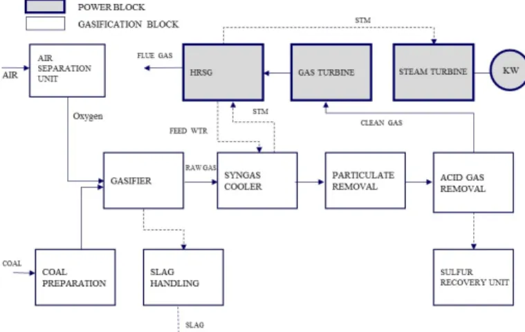
An IGCC plant is composed of two major parts, as shown in Fig. 1: the power block and the gasification block. Although the power block of an IGCC plant looks similar to that of a conventional combined cycle plant, there are several key differences: the power block is integrated with the gasification block, and the operating environment is different. Syngas, which consists mainly of carbon monoxide and hydrogen, has a calorific
value between 4 and 12 MJ/kg. This means that the fuel flow at constant thermal heat input for syngas is higher than for natural gas [14]. Gas turbines are available from manufacturers like GE and Siemens and need only minor modifications to use syngas as fuel. Using syngas as fuel influences gas turbine performance.
Because of the low heating value of syngas, more mass flow of fuel is supplied to achieve a certain limiting turbine inlet temperature. In addition, nitrogen from the ASU and syngas saturation contributes to a higher mass flow through the turbine, resulting in greater power output [15].
The commercial IGCC plant under consideration uses an F- series turbine remodeled for use with natural gas. The output of the turbine (GE and Siemens) is limited to 230 MW, while the single-train (one gasifier + one gas turbine) output of the IGCC plant to which the turbine is applied, is limited to 300 MW. This makes it an inefficient choice because its output is smaller than that of existing pulverized coal power plants. Therefore, this
Fig. 1. Block flow diagram of the IGCC system without CO2 capture.
study chose a G-series natural gas turbine with superior output and efficiency, analyzed its performance after remodeling it for use with synthetic gas through off-design, and verified the results against manufacturer data. Our study has confirmed that an output of 500 MW can be achieved by applying a G-series gas turbine (remodeled for use with synthetic gas) to a single-train IGCC plant.
II. PERFORMANCE ANALYSIS OF GAS TURBINE FOR SYNGAS (IGCC)
Manufacturers do not find it economically viable to produce syngas-compatible turbines exclusively for use in IGCC.
Therefore, the gas turbine for natural gas has been modified to meet the requirements for syngas combustion, given that the calorific value of syngas is as low as one-fourth that of natural gas. The process model is first established based on the gas turbine for natural gas, and then this model is modified for use with syngas. GateCycle [16] was used to simulate the on-design and off-design operation of the gas turbine.
A. Selection of the Gas Turbine (M501G)
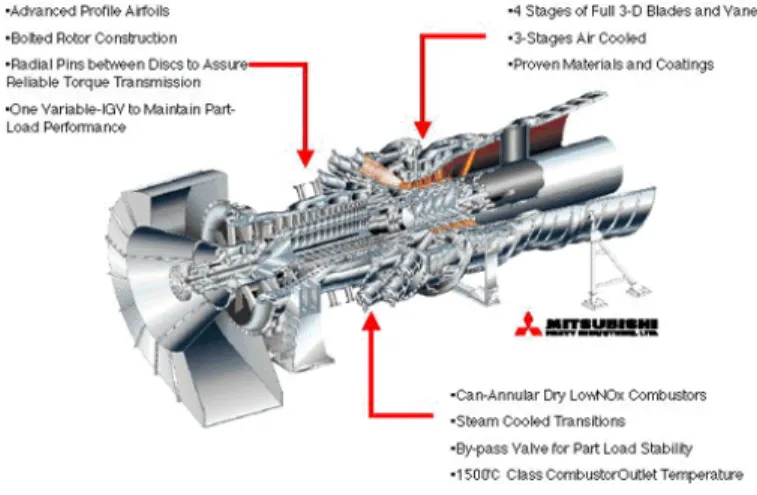
The MHI G-series was chosen as the gas turbine to run the IGCC plant with syngas owing to its excellent power and efficiency, which gives it the technological and economic edge needed to facilitate an entry into the worldwide market. M501G is a can annular combustor with 16 cans and a turbine inlet temperature of 1500 °C, suitable for combustion with a gas of low calorific value. Using natural gas as fuel, it has 267 MW of power, 39.1% efficiency, and an exhaust gas temperature of 600 °C. The system has a 17-stage compressor, a four-stage turbine, and a 20:1 compression ratio as shown in Fig. 2 and Table 1. The cooling air for the turbine rotor and nozzle is obtained from the steam bleeding from the compressor. Fig. 3 shows the turbine cooling system.
B. Modeling the Gas Turbine with Natural Gas
To determine the power, efficiency, exhaust gas temperature, and flow rate of the M501G gas turbine when it uses natural gas as fuel (Table 1), a GateCycle model was established with a compressor, a combustor, and a turbine (Stages 1-4) as separate units, as shown in Fig. 4, instead of using an integrated gas turbine unit model. Air bleeding from the 17th stage of the compressor cools the turbine’s rotor and nozzle. The steam bleeding from the 6th stage of the compressor cools the 4th stage of the turbine; steam bleeding from the 10th stage cools the 3rd stage of the turbine; steam from the 14th stage cools the 2nd stage
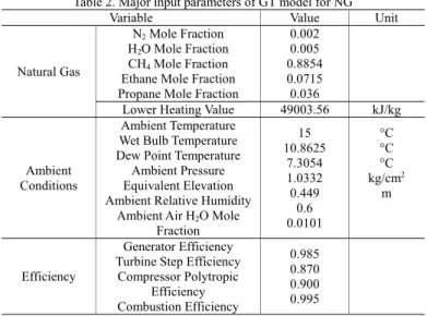
of the turbine, and steam from the 17th stage cools the 1st stage of the turbine. Table 2 shows the inputs for the gas turbine modeling.
Table 3 shows the accuracy of the gas turbine simulation results. The gas turbine power, efficiency, exhaust gas temperature, and flow rate were accurate, and all within a range of ±2%. The difference between the compositions of the natural gas used by the gas turbine manufacturer and the one used in this study seemed to the major source of error.
C. Modeling the Gas Turbine with Syngas 1) Features of the Gas Turbine for Syngas
The calorific value per unit volume of syngas being approximately 30% that of natural gas, the flow rate of syngas needed to be increased correspondingly, by over four times, to achieve the required turbine inlet temperature. The increase in the mass flow rate of the fuel, which implies an increase in the mass flow rate through the gas turbine, also increased the power of the turbine. If the fuel is diluted with nitrogen to control NOx, the power of the gas turbine for syngas is likely to increase further.
However, to fully facilitate this increase in power, the compressor surge, the gas turbine rotor torque, the turbine inlet temperature, and the service life of the high-temperature parts must all be considered. Fig. 5 below shows a typical gas turbine modified for use with syngas.
The increase in the mass flow rate through the turbine may increase the compressor exit pressure, causing a surge in the compressor that may disrupt the airflow rate. The compressor surge limit, which refers to the magnitude of pressure that the
Table 1. M501G gas turbine performance for NG
Description M501G
60 Hz(3600 rpm)
Gas Turbine
Output, MW @ISO 267
Heat Rate, kcal/kWh 2,201 Electrical Efficiency, % 39.1
No. of Stage Compressor 17
Turbine 4
Pressure Ratio 20
Exhaust Temp, °C 600
Exhaust Gas Flow, kg/h 2,157,000
No. of Combustor 16
Fig. 2. M501G gas turbine.
Fig. 3. M501G turbine rotor cooling.
compressor can endure without experiencing a surge, is a design characteristic of the given compressor. The type of the gas turbine determines if the surge becomes a problem, but it does become a problem for largest gas turbines. As for the pressure increase at the turbine inlet (i.e., the compressor exit), a condition of choked flow occurs when the inlet pressure is increased or when the inlet temperature is decreased to increase the mass flow rate through the fixed geometrical shape of the nozzle. The surge problem can be addressed by adding more stages to the gas turbine compressor, widening the cross-sectional area of the turbine, or connecting the airflow to the ASU.
The gas turbine for natural gas uses the DLN (dry and low- NOx) combustor. The fuel for the combustor is premixed with air to reduce the maximum flame temperature and the generation of thermal NOx. This combustor is said to be dry because it does not
spray water or steam to reduce the flame temperature, unlike in the older method. When syngas (coal gas) or hydrogen-mixed gas is used, however, a DLN combustor cannot be used because of the risk of it backfiring owing to the high flame propagation speed and the wide hydrogen combustion range. Accordingly, when the gas turbine for natural gas is modified for use with syngas, the combustor must be changed from the premix flame combustor to the diffusion flame combustor. When syngas is used as fuel, a diffusion flame burner must be used to stabilize the flame.
The gas turbine for syngas mixes most of the nitrogen separated in the air separation unit of the gasification block with syngas and supplies it to the combustor. It therefore increases the power of the gas turbine for syngas, and establishes a stable flame temperature for the combustor to reduce NOx generation.
2) Modeling Conditions for the Gas Turbine for Syngas - The ambient condition is defined by the ISO standard
for temperature and pressure, as in the case of the natural gas turbine.
- The compression ratio is 20:1, and polytropic efficiency is equal to that of the natural gas turbine.
- The air for cooling the turbine nozzle and rotor is obtained from the steam bleeding at the same location
Table 2. Major input parameters of GT model for NG
Variable Value Unit
Natural Gas
N2 Mole Fraction H2O Mole Fraction CH4 Mole Fraction Ethane Mole Fraction Propane Mole Fraction
0.002 0.005 0.8854 0.0715 0.036
Lower Heating Value 49003.56 kJ/kg
Ambient Conditions
Ambient Temperature Wet Bulb Temperature Dew Point Temperature Ambient Pressure Equivalent Elevation Ambient Relative Humidity
Ambient Air H2O Mole Fraction
15 10.8625
7.3054 1.0332 0.449
0.6 0.0101
°C
°C
°C kg/cm2
m
Efficiency
Generator Efficiency Turbine Step Efficiency
Compressor Polytropic Efficiency Combustion Efficiency
0.985 0.870 0.900 0.995
Table 3. Comparison of simulation results with reference data Variable Reference
(MHI) Model Deviation %
GT Power, MW 267.0 264.6 -0.9
GT Efficiency (LHV),
% 39.1 39.7 +1.5
GT Heat Rate (LHV),
kcal/kWh 2,201.0 2,166.2 -1.6
GT Exhaust
Temperature, °C 600.0 604.0 +0.7
GT Exhaust Gas Flow,
kg/h 2,157,000.0 2,197,735.3 +1.9
Fig. 4. GateCycle model of GT for NG.
Table 4. Major input parameters of GT model for syngas
Description Value Unit
Syngas
CO Mole Fraction H2 Mole Fraction
0.644 0.356
Lower Heating Value 14,305 kJ/kg Pressure
Temperature Flow Rate
35.7 200 204,794
kg/cm2a
°C kg/h
N2
Pressure Temperature
Flow Rate
35.7 200 301,963
kg/cm2a
°C kg/h Syngas+N2 Lower Heating Value 6.0 MJ/Nm3
Air
Pressure Temperature
Flow Rate
20.6 455 2,148,766
kg/cm2a
°C kg/h
Table 5. Major results of simulation for syngas
Variable Model Unit
GT Net Power 379,124.1 kW
GT Shaft Power 385,212.6 kW
GT Generator Losses 6,088.5 kW
GT Efficiency (LHV) 45.7 %
GT Heat Rate (LHV) 1,879.6 kcal/kWh GT Fuel Consumption (LHV) 828,760.3 kJ/s
GT Exhaust Temperature 602.3 °C
GT Exhaust Gas Flow 2,655,522.8 kg/h
Fig. 5. Modification of the gas turbine for syngas.
as in the case of the natural gas turbine.
- The combustor exit temperature is 1500 °C, as in the case of the natural gas turbine.
- The flow rate and composition of the syngas supplied to the combustor conforms to the KEPCO-Uhde PSG results.
- The calorific value of the nitrogen and syngas fuel mixture is approximately 6.0 MJ/Nm
3.
- There is no flow of air between the gas turbine compressor and the air separation unit.
3) Results and Discussion of the Model for the Gas Turbine for Syngas
The major input values of a gas turbine for synthetic gas are as shown in Table 4, and the results of the simulation carried out on the basis of the aforementioned assumptions (preceding paragraphs) are shown in Table 5. In general, it’s better to assume polytropic efficiencies remain (close to) constant as opposed to isentropic efficiencies. In off-design cases the polytropic efficiencies constant and the cooling flow rates were calculated using the differential pressure method. The assumption of polytropic efficiency is more likely to be true for the expander than for the compressor, because for the compressor the relative mass flow and pressure ratio can change more independently of each other. In the off-design cases the expanders were set to off- design but the compressor to design mode (its discharge pressure will be determined by the expander inlet area of the first stage expander) because the compressor method in GateCycle has problems converging.
The results of the simulation about the GT output and the
GT exhaust gas flow are as shown in Fig. 6. In a research report by GE [17], it is stated that if a flow rate 14% higher than that of the exhaust gas of a gas turbine for natural gas is used for a gas turbine for synthetic gas, the output rises by 28%. The result of the simulation in this study shows a trend corresponding to the GE report, as shown in Table 6. That is to say, when the gas flow into the turbine was increased by 20.8%, it increased the output by 43.3% when compared to a gas turbine for natural gas. This result is only 1.7% higher than the 41.6% reported by the GE study, implying that the model of the gas turbine for synthetic gas has been accurately simulated. Such a simulation result can be obtained in the case where the combustor outlet temperature of the gas turbine for natural gas is the same as the combustor outlet temperature for synthetic gas.
D. Modeling the Steam Turbine Cycle
1) Conditions for the Steam Turbine Cycle Model
- The superheater, evaporator, and economizer of the heat recovery boiler have 16 sets, as in the case of the Taean IGCC.
- The ambient condition is the ISO condition, as in the case of the natural gas.
- The heat recovery boiler is a three-pressure (HP, IP, and LP), horizontal, and drum type without a duct burner.
- The steam turbine’s main steam conditions are 130 kg/cm
2and 566 °C.
- The steam turbine's reheat steam conditions are 37 kg/cm
2and 566 °C.
- The condenser pressure is 0.0518 kg/cm
2.
- The condenser cooling water is seawater with a 35%
salt content.
2) Results and Discussion of the Steam Turbine Cycle Model A steam turbine cycle process model was developed, as shown in Fig.7. The generator power was 191 MW, and the BOP on-site power was 4 MW. The flue gas in the final stage of the heat recovery boiler was 106 °C, and sufficient heat quantity was recovered and used as the heat source for the steam turbine. Table 7 shows the important performance levels of the steam turbine cycle.
III. CONCLUSIONS
To realize the economies of scale in an IGCC plant, a gas turbine for natural gas with superior output and efficiency ratings was selected, and a modeling and simulation were carried out for a gas turbine for synthetic gas using the software GateCycle. The
Table 6. Comparison of increase of GT power byiIncrease of GT exhaust gas flow
Variable
Model Reference[GE]
(Increase Rate %) (B)
Deviation % (A-B)/A×100 Natural Gas Syngas Increase Rate %
(A)
GT Exhaust Gas Flow, kg/h 264,595.3 379,124.1 20.8 20.8 -
GT Power, MW 2,197,735.3 2,655,522.8 43.3 41.6 +1.7
Fig. 6. Simulation results of GT power and GT exhaust gas flow (NG vs. syngas).
Fig. 7. GateCycle model of steam turbine cycle.
Table 7. Major results of simulation for steam turbine cycle
Variable Model Unit
ST Shaft Power 195 MW
ST Generator Power 191 MW
Net Steam Cycle Power 187 MW
Steam Cycle BOP Losses 4 MW