접수일자: 2014년 2월 4일 심사(수정)일자: 2014년 2월 16일 게재확정일자 : 2014년 2월 20일
†Corresponding author
이 논문은 2011년도 경남대학교 연구년 연구비 지원에 의 한 것임
This is an Open-Access article distributed under the terms of the Creative Commons Attribution Non-Commercial License (http://creativecommons.org/licenses/by-nc/3.0) which permits unre- stricted non-commercial use, distribution, and reproduction in any medium, provided the original work is properly cited.그림 1. LISP 네트워크 구조 Fig. 1. LISP Network Architecture
Mobility Support Architecture in Locator-ID Separation based Future Internet using Proxy Mobile IPv6
Seung-Joon Seok
†Dept. of Computer Engineering, Kyungnam University Abstract
Of several approaches for future Internet, separating two properties of IP address into locator and identifier, is being con- sidered as a highly likely solution. IETF’s LISP (Locator ID Separation Protocol) is proposed for this architecture. In partic- ular, the LISP model easily allows for device mobility through simple update of information at MS (Mapping Server) without a separate protocol. In recent years, some of the models supporting device mobility using such LISP attributes have emerged; however, most of them have the limitation for seamless mobility support due to the frequent MS information up- dates and the time required for the updates. In this paper, PMIPv6 (Proxy Mobile IPv6) model is applied for mobility support in LISP model. PMIPv6 is a method that can support mobility based on network without the help of device; thus, this we define anew the behavior of functional modules (LMA, MAG and MS) to fit this model to the LISP environment and present specifically procedures of device registration, data transfer, route optimization and handover. In addition, our approach im- proves the communication performance using three tunnels identified with locators between mobile node and corresponding node and using a route optimized tunnel between MN’s MAG and CN’s MAG. Finally, it allows for seamless mobility by de- signing a sophisticated handover procedure.
Key Words : LISP, Locator-ID Separation, PMIPv6, Future Internet, Mobility
1. Introduction
In order to accommodate the requirements of future Internet, which are hard to resolve using the current Internet, a new architecture has been required. Among the network architectures proposed so far for future Internet, an approach that separates two roles of IP ad- dress: routing locator (RLOC) and endpoint identifier (EID) has been focused on. It is referred to as Locator-Identifier (LID) Separation and IEEE LISP is a protocol to operate LID separation architecture. The LID separation approach discloses only endpoint identifier (EID) to host device or applications and makes routing locator (RLOC) unrelated to the operation of applications. The LID separation architecture can pro- vide an answer to the following problems, which are hard to resolve in the current Internet.
§ Multi-homing: the function to improve the performance of communication services as
communication devices use simultaneously multiple interfaces connected to several networks
§ Routing scalability: the function to provide routing service effectively even when the network is expanded
§ Security: the function to respond to network security issues effectively
§ Mobility: the function to support effectively the
transfer of devices within network and between
networks without interruption of communications
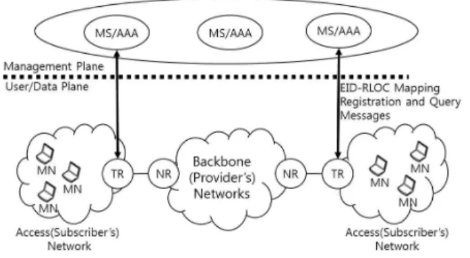
The LID separation/LISP network architecture is as
shown in Figure 1. Location endpoint identifier (EID)
indicates location of the local router through which a
device accesses to Internet; thus, it means the location
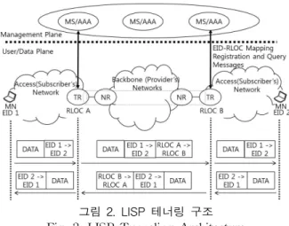
그림 2. LISP 테너링 구조 Fig. 2. LISP Tunneling Architecture of a sub-network in which the device is. In the LISP
network architecture, a management plane system should be built in order to manage the mapping in- formation between an endpoint identifier (EID) and a routing locator (RLOC). This is a query system sepa- rately from DNS and is composed of servers, called as a mapping server (MS), saving entries which have in- formation of RLOC for each EID, priority, load split ra- tio (weight), etc. The server provides the mapping in- formation between RLOC and EID to enquirer device after receiving an enquiry. The strategy of deploying the management plane effectively still remains to be an open issue.
In the LISP scheme, the EID indicates the station it- self and is fixed to the station and, however, a station device doesn’t have to know its RLOC. A station asks a local router to register its EID, and the local locator generates EID-RLOC mapping information and sends it to the management plane / mapping server (MS) before communicating. Also, the locator / RLOC of the station should be changed after station movement. The ID is not, however, changed, regardless of movement.
Several network models for LID separation have been proposed; however, the LISP (locator identifier separa- tion protocol) proposed by Cisco is currently considered as a network model for future Internet in several studies.
Figure 2 shows the data transmission in LISP.
Tunnel routers (TRs), which usually operate as gate- way routers between access networks and Internet, as- signs its address as a RLOC for subordinate stations and register the EID-RLOC mapping information to MS in accordance with the requirement of a device. A de- vice sends a packet, of which header has source and destination EIDs, to its local TR. Then, the TR adds a tunnel header to the original packet and transmits the tunneled packet to the corresponding TR. The tunnel header contains its and corresponding RLOCs as source and destination addresses. The TR queries the RLOC of the corresponding TR to MS using destination EID in- formation extracted from the packet received from the sending station. Lastly, the corresponding TR transfers the packet to the destination station after removing the tunnel header from the tunneled packet.
Whenever a station moves between networks in LISP environments, the mapping of its EID and old RLOC must be changed into new one of its EID and new RLOC which indicates new access network or router. In the case of movement within current network, the map- ping information doesn’t have to be updated. It is re- quired that the mapping information should maintain the latest location information all the time to support mobi- lity effectively in LISP. In case when a station moves at high speeds, in particular, the RLOC may be fre- quently changed as the station. However, a certain pe- riod of time would be required to update the latest lo-
cation information in distributed mapping servers. Thus, it is believed that it would be considered as a load for the management plane when supporting high speed mo- bility for mobile stations.
This paper analyzes the issue of mobility support in the LID separation architecture and presents new strategy. Since the existing LISP based mobility sup- port schemes have the performance limitation of load control for management plane, this paper aims to adopt the proxy mobile IPv6 architecture for network-driven mobility support in IPv6 network to alleviate the load of management plane in LID separation architecture.
As for the configuration of this paper, the second chapter states LISP (locator-identifier separation proto- col), proxy IPv6 and mobility support schemes in the LISP network as the related studies. The third chapter proposes our strategy for mobility support in LISP fu- ture Internet. The fourth and fifth chapters verify the performance of the proposed architecture and draw conclusions.
2. Previous Works
The paper [2] proposes an approach, called as Indirect Mapping (IM), to mobility support in LISP domain. In IM, the network divided into Rendezvous Domain (RD)s and a RD is composed of one Rendezvous Point (RP) and a number of Tunnel Router (TR)s which are representative of each access network.
Each time when a MN accesses to new local network,
TR registers EID of MN and its own RLOC mapping
information in local RP. In the case of new MN entered
in RD, RP registers the EID and RP’s RLOC mapping
information for MN in MS. However, RP just modifies
only TR’s RLOC information when moving between ac-
cess networks within the same RD. As a result, the
mapping information of MS for MN should be changed
in the case of moving to new RD. Unlike the case of
the existing LISP where TR is the routing locator for
그림 3. LISP-PMIP 모델 Fig. 3. LISP-PMIP Model MN, RP of RD becomes the routing locator for MN to
be registered in MS. The benefit of the IM is to reduce the frequent number of MS registration; Thereby, re- ducing the handover delay. However, it may cause data processing overhead and transfer delay as passing through the tunnel up to three times at most.
The papers [10~12] proposes LISP-DHC (distributed handover control) to implement the route optimization and fast handover functions by improving LISP protocol in order to resolve the prolonged delay problem oc- curred when supporting the existing LISP mobility. The access router that performs the function of TR saves both EID-RLOC information of local MN and EID-RLOC information of CN. When a MN moves to new network, the new TR asks MS to updates the mapping information for MN with its RLOC and a tun- nel between the old and new TRs will be generated.
Since then, it will be possible to transfer the data, which is supposed to be transferred to the old TR, to the new TR. Such operation becomes the fast handover function. And also, the new TR requests the old TR for EID-RLOC mapping information of CN related to the MN and implements the route optimization using the mapping information of CN.
The [4] proposes a network model for mobility and routing scalability in future Internet. The proposed model is the one that combines LISP with the overlay network architecture of ALT (alternative logical top- ology). It is the architecture where each regional do- main, in which LISP model is implemented, is connected each other through the ALT Internet backbone. This paper defines MATP (Mobility Anchor Tunnel Point) that is indicated by locator information and performs tunneling between itself and another MATP. There are two types of MATP: G-MATP and L-MATP.
L-MATP is an access router and directly connected by MNs. When a MN moves to new network, new L-MATP conducts the authentication process on new MN and registers EID and locator information for the MN in the GMAT with jurisdiction over its network to generate a tunnel with the G-MATP. G-MATP can find CN’s G-MATP through looking EID up and makes a tunnel between the two G-MATPs in case of need for mobility support. Also from this measure, three tun- nels at maximum would be generated between MN and CN. It would be overhead.
3. A Mobility Support Model for Locator-ID Separation Architecture
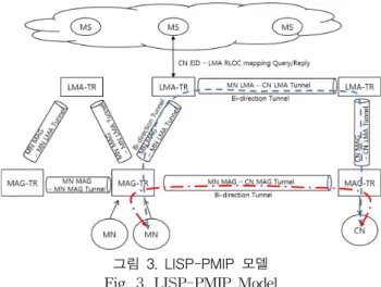
This paper applies PMIPv6 model as a measure of supporting mobility in the LID separation future Internet environment. We refer to this approach as LIDS-PMIP model. Figure 3 describes the LIDS-PMIP model merged LISP architecture and PMIPv6 model for
supporting seamless mobility. Of these, the role of TR in LISP is separated into two devices of LMA-TR and MAG-TR witch are conceptually similar to the LMA and MAG in PMIPv6 model, respectively. The functions of each device are defined in detail as follows:
§ LMA-TR: It is a tunnel router(TR) of LISP protocol which puts a mapping information between mobile node(MN)’s EID (endpoint identifier) – LMA-TR’s Routing Locator (RLOC) on mapping servers’ list in order to distribute the home network’s location of MN and which maintains a bi-directional tunnels between itself and other TRs for the data transfer of the MN.
Also, LMA-TR is a home agent for a MN which maintains the RLOC information of MAG-TR for the MN’s EID and bi-directional tunnels between LMA-TR and MAG-TR.
§ MAG-TR: It is also both a TR and an access router in foreign network for MN. It registers the information mapping MN’s EID - its’ RLOC in LMA-TR in order to tack the current position of MN instead of the mapping servers and sets up the bi-directional tunnel between itself and LMA-TR.
§ MS/AAA(authentication & service server): It is the server that saves the mapping information between MN’s EID and LMA-TR’s RLOC in accordance with LISP model and responds to an enquiry. It also conducts the AAA processes when saving the mapping information for the first time.
§ MN MAG – MN LMA tunnel: A bi-directional tunnel between a LMA-TR that enrolls a MN in home network and a MAG-TR where the MN is currently located. The packets are encapsulated with MAG-TR and LMA-TR RLOCs to pass through backbone Internet. This tunnel has been maintained as long as MN is inside the MAG-TR
§ MN LMA – CN LMA tunnel: A bi-directional
tunnel between two LAM-TRs, to which
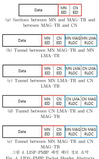
(a) Sections between MN and MAG-TR and between MAG-TR and CN
(b) Tunnel between MN MAG-TR and MN LMA-TR
(c) Tunnel between MN LMA-TR and CN LMA-TR
(d) Tunnel between CN LMA-TR and CN MAG-TR
(e) Tunnel between MN MAG-TR and CN MAG-TR
그림 4. LISP-PMIP 패킷 헤더 정보 요약 Fig. 4. LIDS-PMIP Packet Header Abstracts LMA-TRs of a MN and a Corresponding
Node(CN) belong. The packets are encapsulated with two LMA-TR RLOCs. This tunnel has been maintained during the communication period between the MN and the CN.
§ MN MAG – CN MAG tunnel: A bi-directional tunnel between two MAG-TRs which MN and CN are currently located in, respectively. In this case, tunneling header uses two MAG RCLOs. This tunnel has been maintained before MN or CN moves to other network and during the communication period between the MN and the CN.
The proposed LIDS-PMIP model is based on LISP model. Thus, MN and CN transmit and receive packets using only EID (endpoint identifier). The data packet transmitted by MN at this time would be tunneled through the use of encapsulation header depending on the routing locator (RLOC) after arriving at MAG-TR or LMA-TR, which are TR. The three types of bi-di- rectional tunnel are used in the model. The first is the tunnel between MAG-TR and LMA-TR, referred to as MN MAG – MN LMA tunnel; the tunnel is to trans- mit and receive data packets with MN’s EID between LMA-TR, where the MN is registered, and MAG-TR, in which the MN is located. This tunnel has been maintained as long as the MN is inside the MAG-TR.
The other one is generated and maintained for trans- mission and reception of data packet between the MN and the CN between LMA-TR, to which the MN be- longs, and LMA-TR, to which the CN belongs. We call this tunnel as MN LMA – CN LMA tunnel. At last, LIDS-PMIP model has the tunnel between MAG-TRs.
The tunnel between MAG-TRs is utilized to provide the route optimization and fast handover. The one is MN MAG – CN MAG tunnel and the other is MN MAG – MN MAG tunnel.
MN or CN should put the information mapping MN’s EID and LMA-TR RLOC on the MS’s list first before its communications. We call this operation as a MN-LMA-MS registration. Generally the LMA may be a default access router in home network for the MN.
Thus, unless the MN changes its home network or the LMA-TR, the mapping information which has been registered at the MS should not change. However, the MN’s location information(RLOC) may be changed whenever the MN moves to other networks. So, in LIDS-PMIP model, the MNs and CNs should its EID to local TR, regardless of LMA-TR or MAG-TR, at each time they move or periodically. Receiving the EID in- formation, a LMA-TR registers the information map- ping EID and LMA-TR’s RLOC to MS. But, a MAG-TR sends the information mapping EID and MAG-TR’s RLOC to the LMA-TR which the MN is belong to. This operation is referred to as
MN-MAG-LMA registration or binding update.
Figure 4 describes the header architecture abstracts of data packet in the model (Figure 1). First, Figure 4(a) indicates the abstraction of packet which a MN sends to CN and this packet is n sections between MN and MAG-TR and between MAG-TR and CN. In this case, source address and destination address are MN’s EID and CN’s EID, respectively. Figure 4(b) is the tun- nel header abstraction to be used for the transfer be- tween MN MAG-TR and MN LMA-TR. This tunnel header uses the RLOCs of MAG-TR and LMA-TR as a source and destination addresses, respectively. Figure 4(c) is the tunnel header abstraction between MN LMA-TR and CN LMA-TR and Figure 4(d) is the tunnel header between CN LMA-TR and CN MAG-TR.
At last, Figure 4(e) is the header abstraction for the tunnel directly connected between MN MAG-TR and CN MAG-TR. This is a tunnel for an optimized route.
LMA-TR and MAG-TR manages the binding cache
table internally in order to maintain the tunnel in-
formation for each node or EID. Each table entry should
be updated periodically in order to maintain the tunnels
mentioned above. Table 1 shows the example of
LMA-TR’s binding cache table. The table entry is
classified into two types in accordance with the type
field value. First, if the type field value is LO(local),
[LO/CO] Type EID
[Endpoint ID] RLOC
[Routing Locator] Seq. #
[Count] Life Time
[Second] LMA-TR
[Yes/No] Enable [Yes/No]
LO MN’s Address MAG-TR1’s Address 2 110 Yes No
LO MN’s Address MAG-TR2’s Address 1 150 Yes Yes
CO CN’s Address LMA-TR’s Address 1 99 Yes Yes
표 1. LMA-TR의 바이딩 캐시 테이블 Table 1. Binding Cache Table of LMA-TR
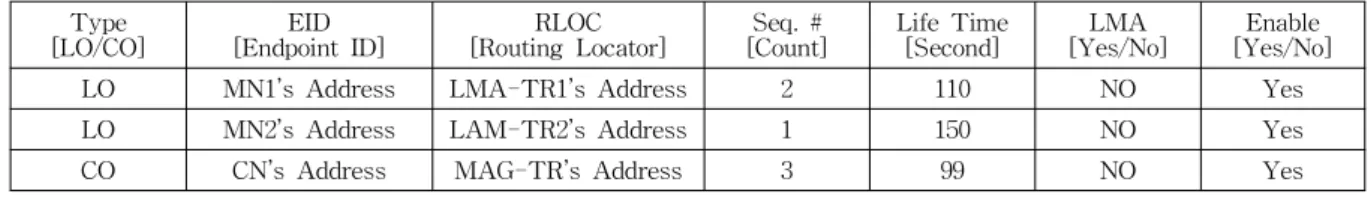
[LO/CO] Type EID
[Endpoint ID] RLOC
[Routing Locator] Seq. #
[Count] Life Time
[Second] LMA
[Yes/No] Enable [Yes/No]
LO MN1’s Address LMA-TR1’s Address 2 110 NO Yes
LO MN2’s Address LAM-TR2’s Address 1 150 NO Yes
CO CN’s Address MAG-TR’s Address 3 99 NO Yes
표 2. MAG-TR의 바이딩 캐시 테이블 Table 2. Binding Cache Table of MAG-TR
그림 5. MN – LMA-TR – MS 등록절차 Fig. 5. MN – LMA-TR – MS
Registration Procedure then the relevant entry display the information on local
MNs that are assigned at its home network with the LMA-TR as a home agent. The EID value is the ad- dress of MN and the RLOC value shows the address of MAG-TR where the MN is currently located. On the other hand, if the type field value is CO(corresponding), then the relevant entries have the information for CN nodes. In this case, the EID is the address of CN that belongs to another and remote LMA-TR and the RLOC is the address of relevant the remote LMA-TR. This LMA-TR’s address can be obtained through an enquiry using CN EID’s from MS. The Seq. # field of the table indicates the number of entry updates and the Life Time field is the period during which the entry validity is continued. The LMA-TR field indicates whether this table is the one of LMA-TR, and lastly, the Enable field orders whether it is possible to use the entry information.
Table 2 is an example of MAG-TR’s binding cache table. In the case when the Type field value is LO (local), the table entry represents the information on node located in the local network of its MAG-TR. In this case, the RLOC value is the one of LMA-TR, which MAG would enquire to MS. On the other hand, if the Type field value is CO (corresponding), the table entry is used for route optimization. So, the RLOC field has the RLOC of MAG-TR, to which CN node is cur- rently belongs.
3.1. Registration Process
Both of LISP and PMIP models have the procedure to register the location for MN when it moves to new network. The proposed LIDS-PMIP model is also de- signed to perform the registration procedure which is a collage of the processes of LISP and PMIP. In short, our model requires that the mapping information be- tween MN EID and TR’s RLOC should be enrolled in MAG-TR, LMA-TR, and MS/AAA. However, the
mapping information, in particular the RLOC value, may be not same location. MS/AAA maintains the LMA-TR’s location information, RLOCs, for a MN EID.
LMA-TR manages the current locations of MNs which belong to itself and are now outside and the home loca- tions of CNs which is communicating with local MNs.
Finally, MAG-TR manages the home locations of MNs which is inside and the current locations of CNs corre- sponding to the MNs. So, MNs should enroll its EID in LMA-TR and/or MAG-TR periodically and at every movement changing networks, then the MAG-TR or LMA-TR makes the registration of the mapping in- formation between MN’s EID and RLOC.
The following Figure 5 shows the procedure for MN
to register in LMA-TR and MS. First, when a new
MN accesses to its home network, it sends the EID
registration message to local LMA-TR through any-
casting or broadcasting. After then, LMA-TR requests
the MS to register the information of MN
EID-to-LMA-TR’s RLOC mapping. MS puts the in-
formation on the list after authentication process on the
그림 6. MN – MAG-TR – LMA-TR 등록절차 Fig. 6. MN – MAG-TR – LMA-TR Registration
Procedure
그림 7. CN-to-MN 데이터 전달절차 Fig. 7. CN-to-MN Data Transfer Process EID and the MN, and then responds the result to
LMA-TR. Lastly, LMA-TR saves the EID’s list in the internal table and a confirm message send to the MN as the response of previous registration. Hereafter, the MN refreshes the validity of the relevant entries through sending the EID update message to LAN-TR periodically.
Figure 6 depicts the registration process of MN when it access to a foreign network. First, MN sends EID registration message to local MAG-TR through any- cating with MAG-TR service address. Then, TR quer- ies MN EID – LMA-TR RLOC mapping information to MS. After receiving the information from MS, the MAG-TR sends a binding update message to LMA-TR to update or enroll MN EID – MAG-TR RLOC map- ping information and receives a confirm message as a response from LMA-TR. And finally, the MAG-TR re- plies to the MN’s EID registration. Through such regis- tration procedures, a bidirectional tunnel for a MN is generated between MAG-TR and LMA-TR.
Like the PMIP model, our LIDS-PMIP model also belies that the MN is below the LMA-TR (home net- work) although it is in foreign network. The MN would communicate with its LMA-TR regardless if it is in home network or foreign network. The MN updates its EID registration of LMA-TR periodically, and also LMA-TR advertises its information periodically. The MN located in home network directly sends the update message to LMA-TR. However, when the MN is in foreign networks, the EID update message should be translated to MN EID – LMA-TR RLOC registration update message and LMA-TR’s advertisement message is transferred to MN through the tunnel between MAG-TR and LMA-TR. Also for hand-off, the proce- dure as above would be conducted among MN, MAG-TR, and LMA-TR.
3.2. Data Transmission Process
If CN and MN are registered in different LMAs each other, then the operation of CN transferring data to MN is as follows (Figure 7). When a MAG-TR receives the data transferred by CN to MN, it looks the routing lo-
cator (RLOC) of LMA-TR for the CN up in its local biding cache table. The MAG-TR adds the tunneling header of CN MAG-TR – CN LMA-TR tunnel and sends it to CN LMA-TR. The CN LMA-TR removes the tunnel header from the received packet and searches the RLOC of MN LMA-TR on the its binding cache table by the MN’s EID. However, finding no entry for the MN, the CN LMA-TR queries MS for MN EID – LMA-TR RLOC mapping information. Since then, CN LMA-TR transfers the data to MN LMA by adding the tunneling of CN LMA-TR – MN LMA-TR tunnel.
MN LMA-TR also transfers the packet to MN MAG-TR by changing the tunnel header of the packet for MN LMA-TR – MN MAG-TR tunnel. At last, MN MAG-TR transfers the original packet to the in- ternal MN after removing the tunnel header. CN LMA-TR and/or MN LMA-TR put a new entry of CO type on their binding cache tables in case of need.
MN LMA-TR sends a route optimization message, which contains CN EID, MN EID, and MN MAG-TR’s RLOC, to CN LMA-TR when receiving the first packet for new communication session between CN and MN.
The CN LMA-TR relays this message to CN MAG-TR. Then, this CN MAG-TR directly sends a registration request (binding update) message to MN MAG-TR and receives a confirm message to make tunnel between these MAG-TRs. This tunnel is re- ferred to as a route optimized tunnel (Figure 8). As a result, a CO type entry with MN EID and MN MAG-TR RLOC mapping information is added to CN MAG-TR’s binding cache table and another one with CN EID and CN MAG-TR’s mapping information is al- so added to MN MAG-TR’s table.
In the case when MN and CN are registered in the
same MAG-TR, the MAG-TR, which received the data
그림 10. MN의 핸드오버 절차 Fig. 10. Hand-over Process of MN
그림 9. 동일 LMA를 사용하는 경우 통신절차 Fig. 9. Communication Process When Using the Same
LMA
그림 8. CN MAG – to – MN MAG 사이에서 최적 터널 생성절차
Fig. 8 Generation Procedure of Optimized Tunnel between CN MAG – to – MN MAG
transferred by MN, relays the packet to the internal MN directly without passing through LMA-TR. As for other cases, when MN and CN utilize the same LMA-TR even though they are registered in a different MAG-TR respectively, LMA-TR relays the original data between LMA-TR – CN MAG-TR tunnel and LMA-TR – MN MAG-TR tunnel. This case is de- picted in Figure 9. After then, LMA-TR sends a route optimization message to CN MAG-TR to generate the optimal route tunnel between the two MAG-TRs.
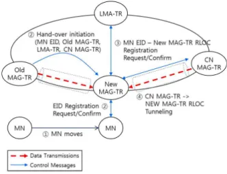
3.3. Handover Process
In case a mobile node (MN) moves from old MAG-TR to new MAG-TR, this mobility process, re- ferred to as handover, is as follows (Figure 10). When a MN starts moving to new MAG-TR, old MAG-TR transfers HI (handover initiation) message to new MAG-TR. HI message includes the information on MN EID, Old MAG-TR RLOC, LMA-TR RLOC, and CN MAG-TR RLOC(s). As soon as receiving the HI mes-
sage, new MAG-TR applies for MN EID - New MAG-TR RLOC registration to LMA-TR and at the same time it transfers the response to HI to old MAG-TR. Soon after receiving this, old MAG-TR sends MN data packets by generating the tunnel be- tween two MAG-TRs. The packets should be stored and forward to the MN after it arrives at new MAG-TR. After a short while, the MN connects to new MAG-TR and immediately sends a MN EID reg- istration message to new MAG-TR in accordance with the existing procedure. Just then, new MAG-TR replies to the registration of MN instead of the LMA-TR.
Also, new MAG-TR replaces the previous route-opti- mized tunnel(s) with new tunnel(s) between new MAG-TR and CN MAG-TR(s) by transferring binding update message(s) with new MAG-TR (registration) to CN MAG-TR(s) which is announced by the HI message. So, the location information of MN is raced by LMA-TR and need not to be updated for every handover process.
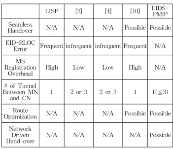
4. Evaluations
This paper compares the proposed LIDS-PMIP model with others which have previously proposed to improve the mobility support of LISP model. Table 3 shows qualitative analysis results between mobility models for LISP in terms of seamless hand-over support, target locator error condition, MS registration overhead, the number of tunnels between MN and CN, route opti- mization support, and network driven hand-over possibility.
Our LIDS-PMIP has been designed to make a tunnel
between old and new MAG-TRs to forward packets
received by old MAG-TR to MN in the middel of
hand-over process in order to make seamless
hand-over. Let’s assume that MN’s hand-over operation
and new CN’s query to MS are carried out simultaneously. In this case, it is possible that the new CN get old locator information for the MN. This is re- ferred to as EID-RLOC error. In our model, the EID-RLOC mapping information of MN stored in MS(s) is fixed and not changed by hand-over. However, LISP and [10] requires that the EID-RLOC of MS(s) should be changed whenever MN moves. Some time is spent on this operation and the EID-RLOC error may happens more frequently than other methods. In [2] and [4], EID-RLOC mapping information of MS is modified only when MN moves between domains, not between neigh- bor networks. However, [2] and [4] make three tunnels when MN and CN are in different domains each other.
In our LIDS-PMIP model, first several packets are transferred through the normal route using three tun- nels and next an optimized tunnel between MN’s MAG-TR and CN’s MAG-TR is developed and all packets are transferred through the optimized route.
Finally, the LIDS-PMIP makes as if MN is in home network always.
In conclusion, we can say that our LIDS-PMIP mod- el has affirmative characteristics in six fields as com- pared to LISP model, [2], [4], and [10].
LISP [2] [4] [10] LIDS-
PMIP Seamless
Handover N/A N/A N/A Possible Possible EID-RLOC
Error Frequent infrequent infrequent Frequent N/A Registration MS
Overhead High Low Low High N/A
# of Tunnel Between MN
and CN 1 2 or 3 2 or 3 1 1(≦3)
Route
Optimization N/A N/A N/A Possible Possible Network
Driven
Hand-over N/A N/A N/A N/A Possible
표 3. 이동성 지원 모델 비교
Table 3. Comparison of Mobility Support Models
5. Conclusions
Even in the future Internet environment, the support for mobility of a device is becoming a very important issue. This paper improved Proxy Mobile IPv6 model, which is the network based mobility model among the measures to support Internet mobility that have been proposed so far, so that it can fit to the LISP model that is the future Internet environment. This is referred to as LIDS-PMIP model. On that account, we defined
anew the functions of MAG-TR, LMA-TR, MN and CN and concretely presented device registration, data transfer, route optimization and handover procedures. In this paper, to improve the transfer performance, we presented the data transfer procedures between CN and MN through three tunnels, whose endpoint are LMA-TRs for MN and CN, and through a tunnel for optimized route, which is between MAG-TRs for MN and CN. At last, this paper defined the handover proc- ess for seamless mobility support in our LIDS-PMIP model. The proposed model can significantly reduce the signaling cost and the hand-over processing delay as compared with the other LISP based measures that have been proposed for mobility support of future Internet.
References
[1] Z. Yan, H. Zhou, H. Zhang, S. Zhang, “A Novel Mobility Management Mechanism Based On An Efficient Locator/ID Separation Scheme,”
Proceedings of International Conference on Future Information Networks , pp. 11-16, 2009.
[2] F Qiu, X Li, H. Zhang, “Mobility Management in Identifier/Locator Split Network,” Wireless Personal Communications , vol. 65, issue 3, pp.
489-514, Aug. 2012.
[3] H. Yunjing, L. Yuhong, Y. Liang, “A Novel Mobility Management Mechanism Based on Destination Address Overwritten and ID/Locator Separation,” Proceedings of International Conference on Innovative Mobile and Internet Services in Ubiquitous Computing, pp. 304-309, 2011.
[4] N. Choi, T. You, J. Park, T. Kwon, Y. Choi,
“ID/LOC Separation Network Architecture for Mobility Support in Future Internet,”
Proceedings of International Conference on Advanced Communication Technology , pp. 78-82, 2009.
[5] H. Luo, H. Zhang, C Qiao, “Efficient Mobility Support by Indirect Mapping in Networks With Locator/Identifier Separation,” IEEE Transactions on Vehicular Technology , vol. 60, no. 5, pp.
2265-2279, June 2011.
[6] A. Natal, L. Jakab, M. Portoles, V. Ermagan, P.
Natarajan, F. Maino, D. Meyer, A. Aparicio,
“LISP-MN: Mobile Networking Through LISP,”
Wireless Personal Communications , vol. 70, issue 1, pp. 253-266, May 2013.
[7] J. Hou, Y. Liu, Z Gong, “Performance Analysis of a Seamless Mobility Support Scheme in the Locator/Identifier Separation Network,”
Proceedings of CSEEE , pp. 159-165, 2011.
[8] L Bokor, Z. Faigl, S. Imre, “Flat Architectures:
Towards Scalable Future Internet Mobility,”
Lecture Notes in Computer Science , vol. 6656 pp. 35-50, 2011.
[9] V. Kafle, H Otsuki, M. Inoue, “An ID/Locator Split Architecture of Future Networks,”
Proceedings of ITU-T Kaleidoscope Academic Conference, pp. 1-8, 2009.
[10] M. Gohar, S. Koh, “Distributed Handover Control in Localized Mobile LISP Networks,”
Proceedings of IFIP Wireless and Mobile Networking Conference , pp. 1-7, 2011.
[11] M. Gohar, S. Koh, “Network-Based Distributed Mobility Control in Localized Mobile LISP Networks,” IEEE Communications Letters , vol.
16, no. 1, pp. 104-107, Jan. 2012.
[12] M. Gohar, J. Kim, S. Koh, “Enhanced Mobility Control in Mobile LISP Networks,” Proceedings of ICACT , pp. 684-689, 2012.
[13] P. Dong, H Zhang, “Mobile ID: Universal-ID based Mobility in Locator/ID Separation Networks,” Proceedings of International Conference on Communications and Mobile Computing , pp. 473-477, 2010.
[14] D. Saucez, B. Donnet, “On the Dynamics of Locators in LISP,” Lecture Notes in Computer Science , vol. 7289, pp. 385-396, 2012.
[15] H. Luo, H. Zhang, C. Qiao, “On The Change Rate of Identifier-to-locator Mappings in Networks with ID/Locator Separation,”
Proceedings of Globecom , pp. 305-309, 2010.
[16] J. Kang, K. Okamura, “Mobility Support through Locator/ID Split Architecture,” Proceedings of ICOIN , pp. 404-409, 2011.
[17] J. Lee, N. Chilamkurti, “Performance Analysis of PMIPv6 based Network Mobility for Intelligent Transportation Systems,” IEEE Transactions on Vehicular Technology , vol. 61, issue 1, pp. 74-85, 2012.
[18] S. Zhuang, K. Lai, I. Stoica, R. Katz, S. Shenker,
“Host Mobility Using an Internet Indirect Infrastructure,” Wireless Networks , vol. 11, no, pp. 741-756, 2005.
[19] K. Lee, W. Seo, D. Kum, Y. Cho, “Global Mobility Management Scheme with Interworking between PMIPv6 and MIPv6,” Proceedings of WIMOB , pp. 153-158, 2008.
[20] Eung-gon Kim, You-mi Moon, Wan-kyoo Choi, Sung-Joo Lee, “Design and Implementation of Multi Platform WireㆍWireless Messaging System Using J2ME,” Journal of The Korean Institute of Intelligent Systems, vol. 11, no. 6, pp. 543-548, Dec. 2001.
[21] In-Ho Ra, “Message Delivery and Energy Consumption Analysis on Pocket Switched Network Routing Protocols,” Journal of The Korean Institute of Intelligent Systems, vol. 23, no. 6, pp. 571-576, Dec. 2013.
[22] Chong Deuk Lee, “Proxy Caching Grouping by Partition and Mapping for Distributed Multimedia Streaming Service,” Journal of The Korean Institute of Intelligent Systems, vol. 19, no. 1, pp. 40-47, Feb. 2009
저 자 소 개