ABSTRACT
The purpose of this article was to introduce guidelines and a protocol for in-office 3D virtual setup of digital orthodontic models by clinicians with experience in using currently available orthodontic virtual setup software.
The procedure for 3D virtual setup consists of pre-setup preparation, crown movement, and post-setup evaluation.
In the first step, the crowns in the digital model are prepared to allow the movement of individual crowns in the 3D virtual space. During the second step, a new occlusion is completed by moving the crowns according to the properly selected arch form and prescription. In the final step, the setup result was evaluated by using visual inspection tools or numeric comparison tools, which are only available in virtual setup software. Establishment of standard protocols and advancement in automatic functions can lead to faster and more accurate 3D virtual setup. (Clin J Korean Assoc Orthod 2019;9(4):280-289)
Key words In-office 3D virtual setup, Digital models, 3D setup software
Introduction of In-Office Three-Dimensional Virtual Setup of Digital Orthodontic Models
Jang Won Sung,1 Hee-Moon Kyung,2 Jae-Hyun Sung,2 Seung-Hak Baek3
1Beomeo Sung Dental Clinic, Daegu, Korea
2Department of Orthodontics, School of Dentistry, Kyungpook National University, Daegu, Korea
3Department of Orthodontics, School of Dentistry, Dental Research Institute, Seoul National University, Seoul, Korea
Dr. Jae-Hyun Sung Dr. Hee-Moon Kyung
Dr. Jang Won Sung
Corresponding author: Seung-Hak Baek Department of Orthodontics, School of Dentistry, Dental Research Institute, Seoul National University,
101 Daehak-ro, Jongno-gu, Seoul 03080, Korea Tel: +82-2-2072-3952 Fax: +82-2-2072-3817 E-mail: [email protected] Received: August 30, 2019 / Revised: October 6, 2019 / Accepted: October 11, 2019 Dr. Seung-Hak Baek
INTRODUCTION
The pretreatment diagnostic orthodontic model setup can aid clinicians in obtaining a clear and direct visualization of treatment objectives.
1The orthodontic model setup also allows precise place- ment of labial or lingual brackets in the indirect bonding system or for fabrication of orthodontic appliances such as clear aligners.
2,3Despite its ability to obtain valuable clinical information, the conventional manual model set- up has disadvantages in terms of time and cost.
Three-dimensional (3D) virtual setup of digi- tal models is becoming popular through the use of 3D computer-aided design (CAD) software.
4,5Since the entire procedure can be completed by 3D CAD software, it is simpler, faster, and clean- er compared to conventional manual model setup.
To perform 3D virtual setup, an operator must be able to select, separate, and move the tooth crowns in 3D virtual space. Since the basic principles of the 3D virtual setup remain unchanged, it can be performed with any free 3D CAD software. How- ever, most of these free software programs are not clinically suitable for a full arch setup because of lack of efficiency.
To produce a clinically viable 3D virtual setup procedure, it is necessary to develop a specifically designed orthodontic virtual setup software pro- gram. Therefore, the purpose of this study was to introduce the guidelines and protocol for an in-of- fice 3D virtual setup of digital orthodontic models using available orthodontic virtual setup software programs.
THE PROTOCOL OF THE 3D VIRTUAL SETUP Subject
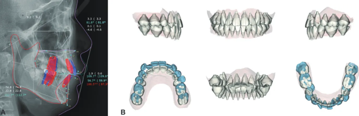
A digital model acquired from a 15-year, 7-month-old male patient was used as an example for the 3D virtual setup. The pretreatment cepha- lometric radiograph and digital dental model indi- cated skeletal Class I (ANB 3.3°, FMA 22.8°), den- tal Class II canine and molar relationships, anterior deep bite, and crowding (Figure 1). The treatment objectives were correction of the deep overbite, resolution of crowding, and achievement of Class I canine and molar relationships. Extraction of up- per first and lower second premolars was planned.
The amount and direction of upper and lower inci- sor movement were determined by a cephalomet-
Figure 1. Pretreatment cephalometric radiograph and tracing (A) and digital dental model (B) of the patient.
A B
ric visual treatment objective (Figure 2).
Standalone orthodontic setup software programs
The 3D virtual setup was carried on the digi- tal model of the same patient using three stand- alone orthodontic software programs. Maestro 3D Ortho Studio 4.0 (AGE Solutions, Pontedera, It- aly) and OrthoAnalyzer 2017 (3Shape, Copenha- gen, Denmark) are well-known popular 3D virtu- al setup software programs with basic functions that allow precise control of tooth movement. Au- tolign 2.0 (Diorco, Suwon, Korea) is a relatively new software program with an automatic aligning function. Screenshots of the three programs were produced during the setup procedure of the same patient.
The three programs are different in details, but the overall workflow of the 3D virtual setup re- mains the same. Most of the detailed procedures described in this article are based on the Maestro 3D Ortho Studio program, because it is suitable for explaining the details of the 3D virtual set- up procedure. The program requires manual ad- justment during every procedure and each tooth movement, and it allows for importing customized
arch form templates.
Pre-setup preparation of a digital model Orientation of the digital model
The global orientation of a digital model, which indicates the position of the upper and lower den- tal arches in relation to the skull, can be registered in 3D virtual space by using conventional meth- ods such as facebow transfer or cephalometric ra- diographs. Convergence of a digital model with a CBCT image can be applied to position the digital model in the 3D virtual space.
However, since tooth movement occurs within the alveolar bone, local orientation of a digital model, positioned according to the patient’s occlusal plane, is a simple and intuitive method (Figure 3).
Segmentation of the crown
Crown segmentation allows a single crown to be moved individually. The software virtually frac- tionates a crown by selecting the crown-gingival junction and cutting it out of a digital model base.
Although most software programs have their own algorithms to recognize crown area and re- contour proximal defects, the tooth contours cal- culated by software must be verified by an opera-
Figure 2. Pretreatment visual treatment objective from lateral cephalometric tracing (A) and 3D virtual setup result (B) for the patient.
A B
tor before proceeding to the next step.
Prescription of the crown axis
Appropriate establishment of the crown axis leads to precise control of tooth movement and prevents undesirable tooth movement in 3D vir- tual space. Since clinical information about the position and movement of the tooth is mostly ex- tracted from the labial surface of the crown, it is recommended to set the crown axis in relation to the crown labial surface.
The orthogonal crown axis, which simply rep- resents the innate state of the crown, can be de- fined to coincide with either the anatomical
crown-root axis or the facial axis of the clinical crown (FACC) (Figure 4). Since the angulation and inclination of the crown is the angle between the FACC and the line perpendicular to the occlu- sal plane, this value can be incorporated into the prescribed crown axis (Figure 4). The method of setting the crown axis can affect the speed and quality of the 3D virtual setup.
Movement of the crown and setup of the virtual occlusion
Selection and arrangement of the arch form template
There are various ways of predicting and find-
Figure 4. Orthogonal axis of the crown by the crown-root axis (A) and by the facial axis of the clinical crown (FACC) (B) and the prescribed axis of the crown (C).
A B C
Figure 3. Coordinate system used in this study. A, Orientation of the dental arch. X-axis represents the transverse direction; Y-axis, anteroposterior (AP) direction; and Z-axis, vertical direction. B, Orientation of the crown. Mesiodistal direction, x-axis; buccolingual direction, y-axis; and occlusogingival direction, z-axis.
A B
ing the individual arch form, such as geometrical drawing using anterior tooth size, mathematical equations from statistical studies, or readymade arch form templates.
6-8During manual setup, it is relatively easy to per- ceive and achieve natural and harmonious align- ment and occlusion by looking at the model and moving teeth with the fingers. However, since the digital model cannot provide physical sensory stimulations, it is almost impossible to achieve a desirable result without the use of an arch form guideline.
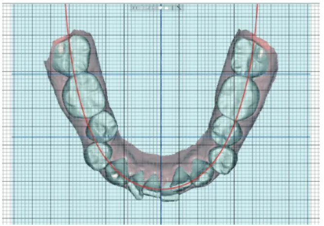
Properly selected digital arch form can also serve as a reference indicator for automatic posi- tioning of the crown (Figure 5).
1. Overlay the selected arch form template on the working plane parallel to the occlusal (X- Y) plane.
2. Hold the camera position for the top-to-bot- tom view directly above the lower occlusal
plane.
3. Shift the template right and left along the X-axis to match the midline of the template with the predetermined lower dental midline according to treatment plan.
4. Shift the template forward and backward along the Y-axis to match the predetermined anteroposterior (AP) position of the lower central incisor.
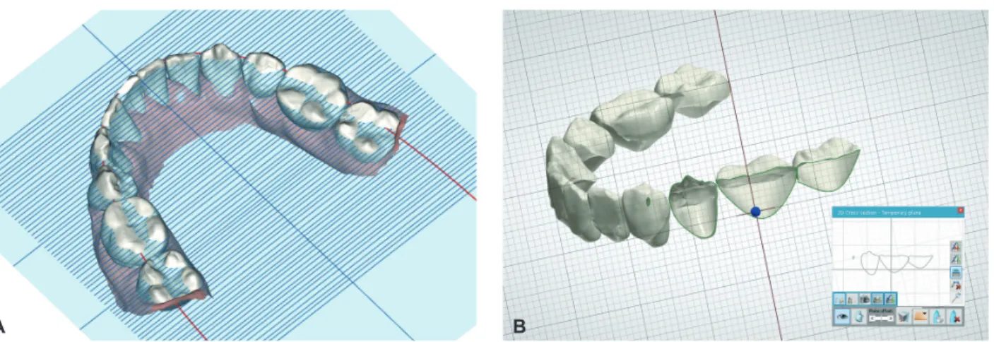
Alignment of the lower arch
When the arch form template is arranged to the predetermined lower incisor position, the po- sitions of the other teeth are automatically deter- mined. Then, the crown must be moved to a posi- tion defined by the arch form template (Figure 6).
The movement of the crowns starts from the lower central incisor and proceeds in the order of lateral incisor, canine, premolars, and molars.
1. Maintain the top-to-bottom view.
2. Upright each crown so the z-axis of each crown is perpendicular to the occlusal (X-Y)
Figure 5. Arch form template arranged to the predetermined lower arch midline and lower incisor AP position. Treatment plans were to maintain the lower midline, extract the lower second premolars for resolution of crowding, and retract the lower incisor by 3 mm to correct the inclination. The midline of the arch form template was arranged to maintain the low- er initial midline. The anterior border of the arch form template was arranged at 3 mm posterior to the initial lower left cen- tral incisor.
Figure 6. Alignment of the lower arch. The crowns of the lower left quadrant are uprighted so the z-axis of each crown is perpendicular to the occlusal plane. The crowns are rotat- ed so the x-axis is parallel to the line of the arch form tem- plate. The first orders of each tooth are also controlled by ad- justment along the y-axis.
plane.
3. Rotate each crown so each tooth is parallel to the line of the arch form template in the me- siodistal direction (x-axis).
4. Shift each crown along the y-axis (buccolin- gual direction) to place an intended promi- nence from the arch form template (1st order).
5. Check and adjust each proximal contact along the arch form template in the mesiodistal di- rection (x-axis) to avoid overlaps or gaps.
Leveling of the lower arch
The buccal cusp tips of the canines, premolars, and molars are good indicators for leveling with the incisal edges of the incisors. However, leveling of the marginal ridges of the posterior teeth is clin- ically more important for settling of the upper and lower teeth and achieving optimal occlusal stops.
Since the marginal ridges are hidden behind the buccal surfaces of the crowns, the clipping view or the horizontal indicator screen must be used to level the marginal ridges (Figure 7).
1. The frontal or right and left views perpen- dicular to the Z-axis should be maintained during the first few steps.
2. Shift the lower incisors along the z-axis to level the incisor edges to the vertical position predetermined by the treatment plan.
3. By rotating the view around the Z-axis from the frontal to lateral side, the cusp tips of the canines, premolars, and molars are leveled in relation to the incisal edges of the incisors.
4. Move the horizontal indicator screen over- laid on the working plane (X-Y) up and down along the Z-axis to identify the height of the marginal ridges. The clipping view of the proximal areas in the mesiodistal direction can provide more precise information.
Detailing of the lower arch
If the prescribed axis is used, the 2nd order and 3rd order position of each crown will already be in place without any further adjustment. If the or- thogonal axis is used, additional rotation of each crown along the y-axis and x-axis is necessary to apply proper 2nd order and 3rd order adjustments, respectively. Figure 8 illustrates the different setup results of the prescribed axis and the orthogonal axis in the upper arch.
On the orthogonal axis, during rotation of the
Figure 7. The horizontal indicator screen can help to identify the level of the marginal ridge (A). The clipping view of the proximal ar- ea in the mesiodistal direction can show the direct image of the level of the marginal ridge (B).
A B
crowns to place the 2nd order and 3rd order, the vertical and horizontal positions of the incisal edges, cusp tips, and contact points can be altered according to the position of the rotation center of each crown. In this case, after placement of the 2nd order and 3rd order, the alignment and level- ing procedures must be repeated in sequence from the central incisor to the second molar.
1. Place the 2nd order and 3rd order, if neces- sary.
2. From the top-to-bottom view, check and ad- just any overlaps or gaps between the proxi- mal contacts.
3. With the grid screen on, check and verify the symmetry of the lower arch.
4. From the frontal view, check the level of the incisors and torque of the posterior teeth.
5. From the split screen view of the right and left sides, check the crown inclination and sym- metry of the anterior teeth.
6. Check the leveling of the marginal ridges with visual aid tools.
Setup of the upper arch
After finishing the setup of the lower arch, the upper teeth should be moved to fit accordingly.
However, there is no agreed upon method of arch form prediction to provide information about up-
per and lower occlusion during 3D virtual setup.
Traditional arch form templates are mostly de- rived from the FACC point. However, the FACC point is relatively difficult to identify from the oc- clusal view during setup. Therefore, a line of oc- clusion that can be easily identified from the oc- clusal view is a better option. An imaginary line through the labio-incisal and bucco-occlusal con- tact between the teeth (bucco-occlusal line, B-O line)
9is the simplest and easiest reference.
The arch form template consisting of upper and lower B-O lines shows the amount of horizontal overjet. However, information about occlusion and the vertical relationship is also needed to com- plete the articulation of the upper and lower den- tal arches. Therefore, if there is a line connecting crown landmarks that occlude one other, the upper and lower teeth may be able to be aligned and ar- ticulated along that line.
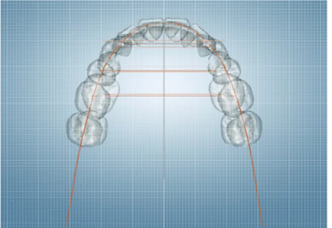
For example, when normal occlusion is estab- lished, the B-O line of the lower arch may occlude the line through the marginal ridges or the central developmental grooves of the upper arch (central fossa line, C-F line). The line that coincides with the B-O line of the lower arch and the C-F line of the upper arch can be used as a single occlusal guideline (Figure 9).
10Once the arch form is selected, the same steps
Figure 8. The crowns of the upper right quadrant are set by the prescribed axis, and the crowns of the upper left quadrant are set by the orthogonal axis. The rear view of the upper arch (A). The split screen view of the right and left sides (B). The 3rd order of the right and left anterior and posterior teeth are different due to the different setting of the crown axis.
A B
performed in the lower arch should be repeated in the following sequence.
1. The AP and transverse positions of the arch form template remain unchanged.
2. Alignment of the upper arch.
3. Leveling of the upper arch.
4. Detailing of the upper arch.
5. Check occlusion with the color map or clip- ping view of the buccolingual cross section.
Post-setup evaluation of the virtual setup model
Assessment and correction of tooth position are simple and clear with 3D virtual setup software because the direction and amount of tooth move- ment are easily determined. The software pro- vides various inspection tools to detect and evalu- ate changes or errors.
The most essential inspection tool is the grid screen overlay, which can be used as a quantifiable reference for crown position. It is also possible to intuitively evaluate the direction and amount of crown movement through superimposition of the
3D virtual models before and after setup.
Final inspection of the 3D virtual setup will fol- low the same sequence as the aforementioned pro- cedure.
1. Verify the initial orientation of the digital model prior to making any changes to an in- dividual tooth. Ensure proper orientation of the midline and occlusal plane of the digital model.
2. Check the lower incisor position and the mid- line to verify that the arch form template is positioned correctly to meet the treatment goal.
3. Evaluate the symmetry and alignment of the lower and upper arches from the top-to-bot- tom and bottom-to-top views, respectively.
Symmetry can be assessed by comparing the distance from the midline of the arch form template to a corresponding landmark on the crowns on the right and left sides. If there is any discrepancy, it must be determined whether the problem was created by rotation, proximal contact, torque, or angulation.
4. Leveling should be checked from frontal and lateral views. Additional tools mentioned above can be used to check the leveling of the marginal ridges.
5. The amount and symmetry of the crown torque should be identified from the frontal view and the split screen view.
6. The amount of occlusal gap or overlap can be identified through the color map or number display.
DISCUSSION
Similar to other general digital procedures, the digital orthodontic workflow consists of three steps: input of information, processing of the da- ta, and output of the result. Input of information
Figure 9. A single line of occlusion, constructed through the marginal ridges or the central developmental grooves of the upper arch or through the labio-incisal and bucco-occlusal contact of the lower arch, is applied for automatic occlusion setup.
requires acquisition of a digital image of the den- tal arch with an optical scanner. Processing of the data involves a 3D virtual setup or appliance de- sign using orthodontic software. Output of the re- sult comes in the form of a displayed image or 3D manufacturing.
Until now, digital orthodontics has mostly been performed by major commercial corporations.
However, recent advancement in technology has introduced more affordable choices of equipment.
Thus, in-office digital orthodontics is now inde- pendent of commercial suppliers.
Among the other steps in a digital orthodontic workflow, 3D virtual setup is a key factor in the success of digital orthodontic treatment. Although 3D virtual setup requires professional knowledge and experience, collection of clinical experience with the 3D virtual setup remains insufficient, and the guidelines to verify the quality of the virtual setup have yet to be standardized. Therefore, con- tinuous research and development are required for 3D virtual setup to be clinically feasible.
Future tasks of 3D virtual setup software Automatic movement of the crowns
With a clear guideline and consistent protocol, 3D virtual setup can be performed in a faster and simpler fashion. Even with simple macroinstruc- tions, automation is possible for most of the tooth movements described above.
Once the proper arch form is selected and the lower incisor position is determined, the simple and repetitive steps listed below can be replaced by a software algorithm.
1. Upright the z-axis of each tooth crown.
2. Rotate each crown so the x-axis parallel or y-axis is perpendicular to the arch form tem- plate.
3. Prescribe the 1st order according to the cho- sen arch form.
4. Perform leveling according to the marginal ridges or incisal edges.
5. Prescribe the 2nd order and 3rd order.
6. Adjust the mesiodistal position according to proximal contact.
Customization of the individual arch form template
Once a proper algorithm is developed, finding a customized arch form for an individual patient may not be a challenging task. Machine learning supplied with enough data, such as digital models before and after treatment, may provide a custom- ized arch form prediction based on the pretreat- ment malocclusion status of the patient and prefer- ence of the orthodontist.
Automatic recognition of tooth morphology Current orthodontic software provides vari- ous grades of automation for crown segmenta- tion. Due to the complexity and variation of tooth crown morphology, self-recognition performance may not be easily accomplished. However, en- hanced machine learning algorithms with a suf- ficient number of tryouts can improve the success rate.
CONCLUSION
Compared to the conventional manual setup with stone casts, the advantages of the 3D virtual setup of digital models using orthodontic software are as follows.
1. Virtual setup is simple, clean, and fast.
2. Quantification and visual comparison of tooth movement are available.
3. Standardization of the protocol allows quality control.
4. Automation of the process is possible with de-
velopment of software algorithms.
5. Unlimited replication and modification are possible while maintaining the integrity of the digital model data.
Establishment of standard protocols and ad- vancement in automatic functions can lead to fast- er and more accurate 3D virtual setups.
REFERENCES
1. Kesling HD. The diagnostic setup with consideration of the third dimension. Am J Orthod 1956;42:740-748.
2. Kyung HM. Individual indirect bonding technique (IIBT) using set-up model. Taehan Chikkwa Uisa Hyophoe Chi 1989;27:73-82.
3. Lew KK. The orthodontic tooth positioner--an appraisal.
Br J Orthod 1989;16:113-116.
4. Kuroda T, Motohashi N, Tominaga R, Iwata K. Three- dimensional dental cast analyzing system using
laser scanning. Am J Orthod Dentofacial Orthop 1996;110:365-369.
5. Motohashi N, Kuroda T. A 3D computer-aided design system applied to diagnosis and treatment planning in orthodontics and orthognathic surgery. Eur J Orthod 1999;21:263-274.
6. Hawley CA. Determination of the normal arch and its applications to orthodontia. Dent cosmos 1905;47:541- 552.
7. Currier JH. A computerized geometric analysis of human dental arch form. Am J Orthod 1969;56:164-179.
8. Nam SE, Kim YH, Park YS, Baek SH, Hayashi K, Kim KN, Lee SP. Three-dimensional dental model constructed from an average dental form. Am J Orthod Dentofacial Orthop 2012;141:213-218.
9. Ricketts RM. A detailed consideration of the line of occlusion. Angle Orthod 1978;48:274-282.
10. Okeson JP. Management of temporomandibular disorders and occlusion. 7th ed. St Louis: Mosby; 2013, p. 50-57.