The Effect of Solution Treatment on Intergranular Corrosion Resistance of a New Type
Ultra Low Carbon Stainless Steel
Wang Julin1, Ni Nannan1, †Yan Qingling2, and Liu Lingli2
1Beijing University of Chemical Technology, Beijing 100029, china
2R&D Center of PetroChina Pipeline Company, Langfang 065000, china
In the paper, with corrosion velocity measurement and metallographic observation on specimens after sulfuric acid/ferric sulfate boiling experiment, intergranular corrosion tendency of the new type ultra low carbon stainless steel developed by ourselves which experienced solution treatment at different temperatures was evaluated. A VHX 500 super depth field tridimensional microscope was used to observe corrosion patterns on the sample surfaces. The depth and width of grain boundary corrosion groove were measured by the tridimensional microscope, which indicated that the corrosion degrees of the samples which received solution treatment at different temperatures are quite different. Transgranular corrosion at different degree occurred along with forged glide lines. After comparison it was proved that the stainless steel treated at 1100 ℃ performs very well against intergranular corrosion.
Keywords : new ultra low carbon stainless steel, intergranular corrosion, metallographic morphology, solid‐solution treatment
†Corresponding author: [email protected]
1. Introduction
During the smelting, welding or heat treatment of metals and alloy, compounds which contain impurities such as C, P and Si etc., and precipitated phase inevitably shall be separated out at grain boundary. Therefore, inter- granulars are preferentially to be oxidized, vulcanized or hydrogenised, resulting to intergranular corrosion.1) So called as intergranular corrosion, with poverty of metal element in alloys in specific media or at high temperature, local corrosion occurs along grain boundary, and binding force between grains is lost.2) This corrosion type which develops into the substrate is invisible on surface, but its reticular structure can be observed with metallographic microscope.
As an important process of metallic material manu- facturing, solution treatment is largely used to achieve even austenite structure, increase corrosion resistance, eliminate work-hardening and soften the steel to ensure easy shaped.3) Additionally, re-solution treatment is the most effective method to prevent intergranular corrosion and precipitation of σ-phase (intermetallic compound of FeC). When stainless steel was heated above solubility
curve (σ-phase disappears above 850 ℃) and kept insulat- ing for a period, the Cr23C6 can be sufficiently dissolved, dispersed and distributed uniformly, then oversaturated austenite structure can be achieved by quick cooling with- out the Cr23C6 separation out. Generally, solution treatment temperature of austenite is from 1050 ℃ to 1150 ℃. The higher content of carbon, the higher solution treatment temperature is needed.4) The samples used in the experi- ment are made of the new type ultra-low-carbon stainless steel which was solution treated at different temperatures.
It was essential to investigate the effect of solution treat- ment on intergranular corrosion resistance of the stainless steel and establish the best solution treatment temperature.
So far, many methods are being used to assess inter- granular corrosion of stainless steel. Different methods were suitable for different kinds of stainless steels. Wu Jinhua,5) Beuhler6) used electrochemical potentiodynamic reactivation (EPR) method to measure the susceptivity of intergranular corrosion and considered the method as an accurate, prompt and ideal one till now. By added NaCl to standard solution of DLEPR and enlarged the concen- tration of H2SO4, Lopez detected the effect of σ-phase on intergranular corrosion resistance of austenite stainless steels and perplex stainless steels.7),8) Zhang Wei etc. stud- ied the susceptivity of intergranular corrosion of 304L us-
ing constant potential erosion method. The result indicated that constant potential erosion may be developed into a prompt test method in this field.9) Using constant current erosion of stainless steel in 10% oxalic acid, Na Shunsang and Tian Wei carried out comparison tests among various electrolytic parameters, and revealed that both electrolytic current and time are main factors to the degree of inter- granular corrosion.10) However, 10% ammonium persul- fate, not 10% oxalic acid, can be used in electrolytic etch- ing of stainless steel which contains molybdenum.11),12) Besides electrochemistry method, chemical erosion of the stainless steel in solutions such as 65% nitric acid, sulfuric acid/cupric sulfate, nitric acid/hydrofluoric acid can also be done on this purpose, after erosion metallographic ob- servation, flexural measurement, weight loss, sonic rang- ing and ultrasonic thickness measurement were used to assess intergranular corrosion of the stainless steel.
Jean-Pierre Celis found intergranular corrosion is induced after a single step pickling in HF electrolyte while not in HCl and the depth of intergranular corrosion obtained from a multi-step pickling is dependent on the successive sequence and duration of the two electrolytes used.13) Fanny Balbaud found corrosion of stainless steels in the nitric acid condensates is far more severe than in the liquid bulk and can lead to intergranular attack even on non-sen- sitized steels.14) Wheeler applied ultrasonic testing to measure stainless-steel pipelines in the coolant water sys- tem of Savannah River Site (SRS) reactors, and the results indicated the presence of short, partly through-wall stress corrosion cracks in the heat-affected zone of approx- imately 7% of the circumferential pipe welds. These cracks were thought to be developed by intergranular nucleation and mixed mode propagation.15)
According to the composition of the new type ul- tra-low-carbon stainless steels, sulfuric acid/ferric sulfate immersion experiment conjunction with weight loss and metallographic observation, intergranular corrosion ten- dency which experienced solution treatment at different temperatures was evaluated. As a double-reagent method, the ferric sulfate was used as passivating agent in sulfuric acid/ferric sulfate system. The method is chiefly used to test intergranular corrosion of austenitic stainless steels containing molybdenum, and intergranular corrosion caused by chromium carbides in un-stabilized austenitic stainless steel (such as 316L, 317L), and also intergranular corrosion caused by both chromium carbides and σ-phase in stabilized austenitic stainless steel (such as 321 etc.) Although 65% nitric acid was also usually applied to test the intergranular corrosion caused by σ-phase, it was often accompanied by severe general corrosion and thus not suit- able in the tests.
2. Experimental
2.1 Chemical composition of the new developed stain- less steel and solution treatment temperatures The composition of samples 1, 2, 3, and 4 was the same as Table 1 and the solid‐solution temperatures were de- scribed in Table 2.
Table 1. Chemical composition of samples (mass weight %)
C Si Mn S P Cr Ni Mo N O Fe
0.002 0.25 0.48 0.003 <0.005 17.60 15.30 2.55 0.0025 0.0024 rest
Table 2. Solution treatment temperature (℃) No. solution treatment temperature
1 Without treatment
2 900
3 1000
4 1100
Remark: Solid solution treatment duration was two hours.
2.2 Sulfuric acid/iron sulfate immersion test (GB/
T4334.1-2000) 2.2.1 Test solution
Mixing sulfuric acid (GR) with distilled water of the same weight. Put 12.5 g of iron sulfate into 300 ml of the solution and heat the solution till complete dissolution.
2.2.2 Test apparatus and equipment
(1) 500 ml ground glass stoppered conical flasks with condensation reflux pipes were used as experi- mental containers;
(2) A set of heating facility which can keep the solution slightly boiling;
(3) A square calliper was used to measure the super- ficial area of the samples;
(4) A set of electronic balance was used for samples weight measurement.
2.2.3 Test procedure
(1) Measuring the sizes of samples and calculating their superficial areas;
(2) Weighing samples before the test;
(3) The quantity of solution was determined by the su- perficial area of samples, which should not be less than 20 ml/cm2. The solution must be new prepared for each test;
(4) Samples were positioned at the middle of the sol- ution with a glass support. Keep boiling for 120 hours;
(5) Took out the samples after test. Scrubbed off corro- sion product from samples in running water with
(a) (b)
(c) (d)
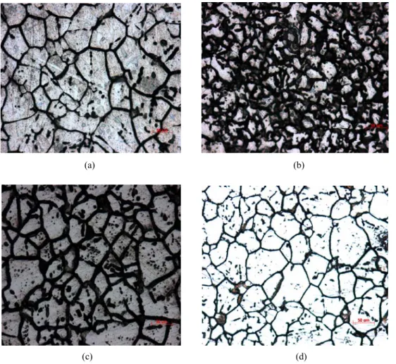
Fig. 1. Metallograph of the new type super-low-carbon stainless steels which has been treated at different temperatures in sulfuric acid/ferric sulfate solution
soft brush, then rinsed the samples with distilled water and weighed them.
2.3 Test of corrosion rate and observation of the corrosion patterns on samples surface
After erosion in sulfuric acid/ferric sulfate the samples were taken out and scrubbed off corrosion product in run- ning water with soft brush, then rinsed with distilled water and surveyed the corrosion rate by weight loss. An Axioplan2 universal material microscope (Zeiss company, Germany) was used to observe corrosion patterns on the sample surface and assess intergranular corrosion class, while a VHX-500 super-deep focus tridimensional micro- scope (Keyence company) was used to the observe tridi- mensional corrosion patterns on sample surface and meas- ure depth and width of grain boundary corrosion channels.
3. Results
According to GB/T4334.1-2000, the weight loss of stain-
Table 3. General corrosion rates of stainless steel samples experienced sulfuric acid/iron sulfate erosion test
Samples 1 2 3 4
general corrosion rate
(g/m2.h) 0.64 0.71 0.60 0.40
less steel samples which experienced 120 hours sulfuric acid/ferric sulfate erosion test is used to calculate the gen- eral corrosion rate (g/m2.h). The results are shown in Table 3.
The increasing sequence of the general corrosion rates of stainless steel samples is 4, 3, 1, 2.
Fig. 1 is metallograph morphology of the new type su- per-low-carbon stainless steels which had been treated at different temperatures in sulfuric acid/ferric sulfate solu- tion. From Fig. 1, it can be seen that the new type su- per-low-carbon stainless steels which had been treated at different temperatures are all subjected to intergranular corrosion at different degrees, grain-boundary corrosion ditches are obvious on each sample surface. The most se- vere one among them is No. 2 sample, which has wide
Fig. 2. (a) No.1 (without solid solution treatment)
Fig. 2. (b) No. 2 (solid solution treatment at 900 ℃)
Fig. 2. (c) No. 4 (solid solution treatment at 1100 ℃)
Fig. 2. Tridimensional pattern view of the new type ultra-low- carbon stainless steels experienced treatment at different temperatures subject to sulfuric acid/iron sulfate erosion test
and deep grain-boundary corrosion ditches, in addition with some grains pulled off. Sample 3 is less corroded, and the grain-boundary is consecutive with no grains pulled off. Some grain-boundary corrosion ditches on No.1 sample are comparatively obvious, while some grain-boun- dary is not consecutive. Corrosion status on it is remark- ably slighter than sample 2 and 3. Grain-boundary corro- sion ditches on No. 4 sample are narrow and shallow.
Some grain-boundary is not consecutive. Intergranular cor- rosion resistance is prominently the best. The increasing sequence of intergranular corrosion resistance of the new type ultra-low-carbon stainless steels is 4, 1, 3, 2, which conforms to the result of weight loss.
Fig. 2 is a tridimensional pattern view of the new type ultra-low-carbon stainless steels experienced treatment at different temperatures subject to sulfuric acid/iron sulfate
erosion test. It reveals ulteriorly the large difference of intergranular corrosion status of them. In Fig. 2, the max- imum depth of grain-boundary corrosion ditches on No.
1 sample (without solid solution treatment) is 4.6 μm, and grains separate from each other. A little corrosion occurs in grains. As for No. 2 sample, grains have been fragmen- taryly corroded. Grain boundary corrosion ditch on No.
2 sample is 5.9 μm deep. Because of severe abscission of grains, height curve of surface does not wave severely.
Grain boundary corrosion ditch on No. 4 sample is only 2.2 μm deep. It can also be found in Fig. 2 that the new type super-low-carbon stainless steels which both experi- enced treatment at different temperatures or without treat- ment not only corrode on grain‐boundary, but also on the grains at different degrees. Making No. 4 sample as an example, Fig. 2(c) is a tridimensional pattern view of a whole grain of the new type super-low-carbon stainless steel which experienced treatment at 1100 ℃ and then suf- fered sulfuric acid/iron sulfate erosion test. In Fig. 2(c), grains completely protrude. Corrosion appears not only on the grain-boundary, but also in grains as black corrosion region. After measuring the height of grains layer, it is found that the black corrosion region is deeper than surface around and is sunk. Shown as Fig. 3, these ribbons exactly position along with forged glide lines. In order to improve the resistance of austenitic stainless steel against inter- granular corrosion, it is discovered that proper cold-work- ing (such as forging) can be helpful to change the core forming position of carbon compound, and impell precip- itation phase to separate out along with glide lines in grains and reduce the amount of grain-boundary precipitation.17) Therefore, both No. 1 and 4 samples with relative higher resistance to intergranular corrosion are corroded along with forged glide lines.
4 Discussions
There were much mechanism causing intergranular cor- rosion, general thinking was the poverty of alloy elements on grain boundary, in other words, electrochemical non-uniformity caused by poverty of chrome in solid sol- ution which connect edges of the grains. If austenitic stain- less steel was kept at temperature from 450 ℃ to 850 ℃ for enough duration, carbon existed at edges of grains would firstly react with chrome which was contained in Fe-Cr-Ni solid solution at the brim of grains to form Cr23C6 (because chrome tended to form carbide than iron and nickel). Cr23C6 precipitated at the grain-boundary of austenite resulted in decreasing of chrome concentration in solid solution which located among grains. With the reducing of content of chrome in solid solution, its elec-
Sample 1
sample 4
Fig. 3. Photographs of ribbon-like corrosion along forged lines on No. 1 and 4 samples
trode potential changed correspondingly. If the mass per- cent of chrome in solid solution near edges of grains was lower than 12%, the area became to an active region in many kinds of electrolytes. In galvanic couple which was formed with chrome poverty area as its anode and normal chrome content solid solution as its cathode, small anode region and large negative zone made the active region sub- ject to consuming corrosion and damage.18) Within certain scope of solid solution temperatures, with increasing of the temperature, both dissolvability of carbon and nitrogen in austenite and diffusion velocity of the elements were speeded up, the grain‐boundary absent of chrome was not easy to form. In this case, although Cr23C6 started pre- cipitating for a long time, it did not bring materials the tendency of intergranular corrosion. In the contrary, de- creasing temperature might slower diffusion velocity of the elements and quicken precipitated speed of Cr23C6, therefore chrome compensated for grain‐boundary is not enough to balance the consumption. Once if the content of chrome reduced to certain level, materials would tend to intergranular corrosion.19) Maysa Terada pointed that the solution-annealed samples and those aged at 1173 K did not present susceptibility to intergranular corrosion,
whereas aging treatment from 873 to 1073 K resulted in small susceptibility to intergranular attack that decreased with aging temperature increase. The preferential for- mation of MoC at higher aging temperatures com- paratively to Cr23C6, retained the chromium in solid sol- ution reducing susceptibility of steel to intergranular corrosion.20) But it needed to be noticed that with decrease of carbon in stainless steel, precipitation of Cr23C6 reduced correspondingly at the grain-boundary, both chances of forming regions absent of chrome and the tendency of in- tergranular corrosion were reduced. Korostelev showed that there was a maximum permissible carbon content lev- el, below which stainless steel would not subject to inter- granular corrosion.21) Austenitic stainless steels are classi- fied into three grades according to the content of carbon:
general amount of carbon (Wc<0.14%), low carbon class (Wc<0.06%) and ultra-low-carbon class (Wc<0.03%).
Because the maximum mass percent of carbon dissolved in austenite can be 0.02%-0.03% at room temperature, in principle, intergranular corrosion would not occur in ul- tra-low-carbon austenitic stainless steels if their chemistry composition was qualified. But such resistant to inter- granular was not absolute, under certain conditions, such as with the existence of strong oxidizing agent, inter- granular corrosion can also occur.22)
In many cases, intergranular corrosion occurred in ul- tra-low-carbon austenitic stainless steels was caused by precipitation of another high chrome content phase along the edges of grains. The first was σ-phase or submicro- scopic α-phase, which resulted in absence of chrome at grain-boundary. Additionally, because σ-phase was more resistant to corrosion than γ-phase (the phase composed of solid solution), the region lack of chrome will be cor- roded under strong oxidation‐reduction potential.23) Secondly, segregation of impurity at grain-boundary can also resulted in severe intergranular corrosion in su- per-low-carbon austenitic stainless steels. The theory was put forward aiming to intergranular corrosion of stainless steels in strong oxidizing medium. It was considered that in this case, selective solution of impurity (such as P and Si) which segregated at grain-boundarywas the main rea- son of intergranular corrosion in stainless steels.24) The effect of Si on tendency of intergranular corrosion of stain- less steels was complicated. Someone thought that corro- sion resistance of passivating film containing Si is better than those without Si because of passivation function of Si. However, if high Si passivating films was formed only on grains surface, at meanwhile the same corrosion re- sistant film can not be achieved at grain-boundary, differ- ence between two kinds of films will result in intergranular corrosion. When mass percent of Si was more than 4%
or less than 0.1%, intergranular corrosion would not tend to occur in the stainless steel. Another theory in view of grain-boundary energy considered that deficiency of Si is easier to lead to segregation of impurity on grain-boun- dary, which made the grain-boundary have comparative high energy resulting in intergranular corrosion.25) Other studies indicated that the content of impurity phosphorus absorbed at grain-boundary is related with solid solution temperature and the corrosion degree at grain-boundary increase rapidly with the content increment of phosphorus.26) Concern of the composition of the ultra-low-carbon stain- less steels in this experiment, there are infinitesimal carbon and certain amount of Si and P. The relative severe inter- granular corrosion occurs in samples which experienced solution treatment at 900 ℃ and 1000 ℃ may be caused by aliquation of impurity (Si and P) on grain-boundary, or by the precipitation of σ-phase.
The new ultra low carbon stainless steels in the experi- ment contain certain amount of Si and P. After solution treatment at different temperatures, the adsorption differ- ence between phosphorus and Si at grain-boundary leads to different resistance to intergranular corrosion.
Mentioned as above, solid-treatment temperatures influ- enced intergranular corrosion of stainless steel through in- fluencing dissolvability, diffusion velocity of some ele- ments in it, or precipitation and dissolution velocity, posi- tion and phase change of deposit phase. Shimada dis- covered slight pre-strain annealing at a relatively low tem- perature can result in excellent intergranular corrosion re- sistance due to optimized grain boundary character dis- tribution (GBCD), i.e. the uniform distribution of a high frequency of coincidence site lattice boundaries and con- sequent discontinuity of random boundary network in the material.27)
In the experiment, the new type super-low-carbon stain- less steel experienced treatment at 1100 ℃ performs ob- viously better resistance to intergranular corrosion. On the contrary, resistance to intergranular corrosion of the steel which experienced treatment at 900 ℃ and 1000 ℃ are worse than No. 1 sample which had not been treated at all. This indicates that solution treatment technology can weaken or erase tendency of intergranular corrosion of al- loys in some cases, and can also accelerate it in other cease. Therefore, it is necessary to carry out test for best solution treatment temperature and excellent resistance to intergranular corrosion.
5. Conclusions
Both sulfuric acid/ferric sulfate weight loss analysis and metallographic observation indicates that the newly devel-
oped super-low-carbon stainless steel which experienced treatment at 1100 ℃ performs obviously better resistance to intergranular corrosion. On the contrary, resistance to intergranular corrosion of the steel treated at 900 ℃ and 1000 ℃ are worse than No. 1 sample which had not been treated.
References
1. H. Dechang, Metal structure and corrosion resistance, Universe publication, 12, 165 (1987).
2. W. Zhenhui and L. Yong Li, China Science and Technology Information, 10, 78 (2005).
3. S. Xiaojun, Heat Treatment, 11, 31 (1999).
4. F. Likui, Heat Treatment of Metals, 11, 205 (1998).
5. W. Jinhua, Standard and Quanlity of Metallurgy, 39, 112 (1996).
6. H. E. BEuhler, L. Gerlach, O. Greven, and W. Bleck, Corrosion Science 45, 2325 (2003).
7. N. Lopez, M. Cid, and M. Puiggali, Corrosion Science 41, 1615 (1999).
8. N. Lopez, M. Cid, M. Puiggati et al., Materials Science and Engineering 229, 123 (1997).
9. Z. Wei, T. Hong, and L. Jiuqing, Corrosion Science and Protection Technology, 4, 214 (1997).
10. N. Shunsang and T. Wei, Physical Testing, 11, 78 (2001).
11. Serial books of corrosion and protection-Local corrosion of metals, Chinese Corrosion and Protection Institute, P23, Chemical Industry Publication, 1987.
12. U. K. Mudali, C. B. Rao, and B. Raj, Corrosion Science 48, 783 (2006).
13. J. P. Celis, L. F. Li, Scripta Materialia 51, 949 (2004).
14. F. Balbaud, Ge rard Sanchez, P. Fauvet, Ge rard Santarini, Ge rard Picard, Corrosion Science 42, 1685 (2000).
15. D. A. Wheeler, D. E. Rawl, and M. R. Louthan, Materials Characterization 32, 25 (1994).
16. G. Zhongping, C. Fancai, and Z. Changjiu, J. of Chinese Society for Corrosion and Protection, 20, 146 (2000).
17. H. De, Metal structure and corrosion resistance, P12, Changchun universe publication, 1987.
18. L. Junmei, Phosphoric Fertilizer and Compound Fertilizer, 3, 45 (1999).
19. Serial books of corrosion and protection-Local corrosion of metals, Chinese Corrosion and Protection Institute, P45, Chemical Industry Publication, 1987.
20. M. Terada, M. Saiki, and I. Costa, Journal of Nuclear Materials, 358, 40 (2006).
21. A. B. Korostelev, V. Ya, Abramov, and V. N. Belous, Journal of Nuclear Materials, 233, 1361 (1996).
22. Z. haisheng, Electrochemical Engineering Technology, 3, 78 (2004).
23. L. Guijin and S. Jiebing, Photoelectricity Counterwork and Disturbance without Resourse, 4, 213 (2002).
24. W. Jian, Intergranular Corrosion, 3, 48 (1998).
25. Serial books of corrosion and protection-Local corrosion of metals, Chinese Corrosion and Protection Institute, P87, Chemical Industry Publication, 1987.
26. Serial books of corrosion and protection‐Local Corrosion of Metals, Chinese Corrosion and Protection institute, P104, Chemical industry publication, 1987.
27. M. Shimada, H. Kokawa, Z. J. Wang, et al., Acta Materialia 50, 2331 (2002).