507
PISSN 0304-128X, EISSN 2233-9558
고분자전해질연료전지에서 수소투과도 측정법의 비교
오소형 · 윤재원 · 이대웅 · 박권필† 순천대학교 화학공학과 57922 전라남도 순천시 중앙로 235
(2019년 2월 27일 접수, 2019년 4월 15일 수정본 접수, 2019년 4월 16일 채택)
Comparison of Measurement Method of Hydrogen Permeability in Proton Exchange Membrane Fuel Cell
So-Hydong Oh, Jeawon Yun, Daewoong Lee and Kwonpil Park†
Department of Chemical Engineering, Sunchon National University, 235, Jungang-ro, Suncheon-si, Jeollanam-do, 57922, Korea (Received 27 February 2019; Received in revised form 15 April 2019; accepted 16 April 2019)
요 약
고분자전해질 연료전지(PEMFC)의 고분자막 내구성을 평가하는데 수소투과도가 많이 사용되고 있다. 수소투과도를 쉽게 측정하는 방법으로 선형 주사 전압 측정법(Linear Sweep Voltammetry, LSV)이 주로 사용된다. 연구자마다 LSV 측정 방법에 차이가 있어 연구 결과를 비교하기가 어려울 때가 많다. 그래서 본 연구에서는 측정하기 어렵지만 정확한 값이라고 할 수 있는 기체 크로마토그래프에 의한 수소투과도와 DOE와 NEDO의 LSV 방법을 비교하여 정확성을 확 인하고자 하였다. 온도와 상대습도를 변화시키며 수소투과도를 측정해 비교했을 때, DOE LSV 방법이 GC 방법과 비 교해 오차 범위 5%이하의 정확성을 보였다. NEDO LSV 방법은 DOE방법과 같이 0.3V의 전류 값으로 수소투과전류 밀도를 결정했을 때 오차는 감소하였다.
Abstract − Hydrogen permeability is widely used to evaluate the polymer membrane durability of polymer electrolyte fuel cells (PEMFC). Linear sweep voltammetry (LSV) is mainly used to measure hydrogen permeability easily. There are many differences in LSV measurement method among researchers, and it is often difficult to compare the results.
Therefore, in this study, we tried to confirm the accuracy by comparing the hydrogen permeability of LSV method and gas chromatograph which is difficult to measure but accurate value. The LSV method used the DOE and NEDO meth- ods. When the hydrogen permeability was measured by varying the temperature and the relative humidity, the DOE LSV method showed an accuracy of less than 5% in the error range compared with the GC method. In the NEDO LSV method, the error was reduced when the hydrogen permeation current density was determined at the current value of 0.3 V as the DOE method.
Key words: PEMFC, Hydrogen permeability, Linear Sweep Voltammetry, Gas chromatograph, DOE
1. 서 론
낮은 온도에서 화학에너지를 전기에너지로 직접 변환시켜 높은 에너지 전환 효율을 갖으며, 환경 친화적이기 때문에 다양한 분야에서 전력 공급원으로 각광받고 있는 고분자 전해질 연료전지는 짧은 수 명, 높은 가격 때문에 시장확대가 지연되고 있다[1,2]. 적용 분야에 따라 5,000시간에서 40,000시간 정도의 수명을 요하는 고분자 전해질
연료전지는[3] 장시간 운전하는 동안 MEA (Membrane and Electrode Assembly)를 구성하는 요소들이 열화 되어 이 같은 수명 목표를 충 족시키지 못하고 있다[4-9].
전해질 막의 열화는 화학적/전기화학적 열화, 기계적(mechanical) 열화로 크게 분류된다[3]. 화학적/전기화학적 열화는 셀 내에서 발생 한 라디칼/과산화수소가 고분자막을 공격해 막이 열화되는 것을 말 한다[3,10]. 전해질 막이 열화되면 막이 얇아지고 핀홀 등이 형성되 어 수소 투과도가 증가하는데 이 수소 투과도를 측정하여 전해질 막 열화정도를 분석한다. 수소 투과도를 전기화학적으로 측정하는 방 법으로 LSV(Linear Sweep Voltammetry)를 주로 사용하고 있다.
LSV 방법은 anode와 cathode에 각각 수소와 질소를 공급하고, 수소 crossover에 의해 나타나는 전류 값을 측정하는 방법이다[3,11,12].
†To whom correspondence should be addressed.
E-mail: [email protected]
‡
이 논문은 연세대학교 설용건 교수님의 정년을 기념하여 투고되었습니다.
This is an Open-Access article distributed under the terms of the Creative Com-
mons Attribution Non-Commercial License (http://creativecommons.org/licenses/by-
nc/3.0) which permits unrestricted non-commercial use, distribution, and reproduc-
tion in any medium, provided the original work is properly cited.
전압을 일정 속도로 증가(Linear Sweep)시키면 투과된 수소가 cathode 쪽 백금 촉매 상에서 산화 반응하여 전자를 내놓게 되는데 이 전자의 양을 측정하면 막을 통과한 수소 양을 알 수 있다.
고분자 막의 내구성을 평가하기 위해서는 수소투과도 측정이 매우 중요하다[13]. 전기화학적으로 쉽게 측정할 수 있어 LSV방법을 많 이 사용하고 있으나 LSV 측정방법에 따른 정확성에 대해서는 명확히 밝혀진 바 없다. GC 방법은 LSV방법보다 복잡하지만 수소농도를 측정함으로써 수소투과도를 정확히 측정할 수 있다[14]. 일반적으로 많이 이용되는 미국 DOE (Department of Energy)나 일본 NEDO (New Energy and Industrial Technology Development Organiation)의 가속열화 프로토콜은 거의 비슷하나, LSV 분석 방법상에 차이가 있 다[15,16]. 그래서 본 연구에서는 이들 LSV 방법들을 GC방법과 비 교 검토해 정확성을 확인하였고, 기존의 LSV방법을 개선한 보다 정 확한 수소투과도 측정방법을 연구하였다.
2. 실 험
막 두께가 18 µm, 촉매 로딩량이 anode와 cathode 각각, 0.2, 0.4 mg/
cm2이고 전극면적이 25 cm2인 MEA (Membrane and Electrode Assembly)와 GDL (Gas Diffusion Layer)을 셀에 80토크로 체결하 였다. 셀을 구성하는 분리판(separator)의 유로 면적비가 기체의 막 투과도에 영향을 줄 수 있는데, 본 실험에서는 유로 면적이 50%인 분리판을 사용했다. 셀의 온도, 유량, 상대습도(RH) 등을 Station (CNL Energy Co, Korea)으로 제어하였다. MEA를 활성화 시키고 일반적인 PEMFC 구동조건(70oC, 100%RH, anode 1.5 stoi. cathode 2.0 stoi.)에서 I-V 성능 곡선을 측정하였다. I-V 성능이 0.6 V에서
1,100 mA/cm2인 MEA 로 기체 투과도 실험을 하였다.
수소투과전류밀도는 Potentiostat (Solatron, SI 1287)을 이용한 LSV방법으로 수소투과 전류를 측정해 비교하였다. LSV는 anode와 cathode에 각각 수소와 아르곤을 공급하고, 전압을 변화시키면서 전류 를 측정하였다. DOE와 NEDO의 LSV분석법이 차이가 많은데 Table 1에 비교하였다.
열전도도 검출기(TCD)와 분자체 칼럼(molecular sieve column, 5A F-3847, 3.0 m, 3.0 mm ID)을 장착한 기체 크로마토그래프(GC, SHIMADZU GC-4B)로 수소 농도를 측정하였다. Injection port 와 column, 검출기의 온도는 각각 100oC, 40oC, 110oC를 유지 하였다.
5,000 ppm 수소 표준가스를 기체 혼합기에서 고순도 아르곤과 혼합 해 2,500 ppm, 1,250 ppm, 625 ppm 수소로 만들어 검량곡선을 작성 하였다. PEMFC anode에는 수소 가스를, cathode에는 아르곤 가스를 일정 유량으로 유입하고 cathode 출구 가스를 응축기(-5oC)를 통과시 킨 후 GC 유입구 직접 유입해 수소 농도를 측정하였다.
3. 결과 및 고찰 3-1. GC에 의한 수소투과도 측정
전기화학적으로 분석하는 수소투과도 측정이 측정 방법에 따라서 얼마나 정확한지 본 연구에서 알아보기 위해서 그 기준으로 GC에 의한 수소투과도를 측정하였다.
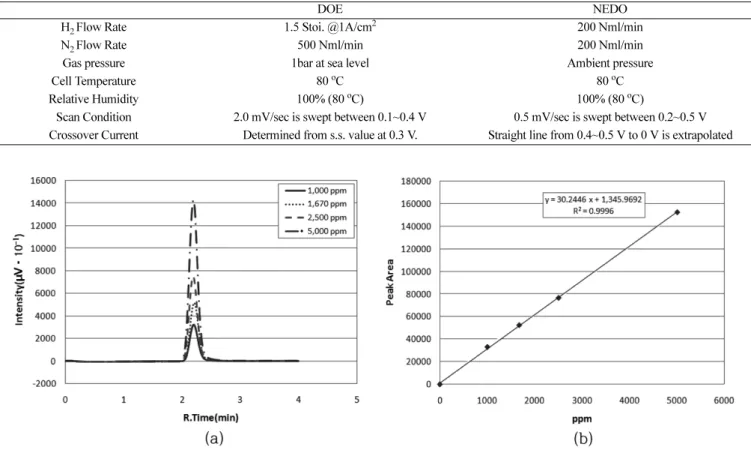
아르곤과 혼합된 5,000 ppm의 표준 수소 가스와 고순도 아르곤 가스를 일정 유량으로 기체 혼합기에 공급해 수소 농도를 변화시키 면서 GC로 수소 양을 분석해 Fig. 1의 그래프와 검량 곡선을 얻었다.
GC 그래프 상에서 불순물이 없음을 확인할 수 있으며, 가스 혼합
Fig. 1. Gas chromatograph (a) and calibration curve of hydrogen (b).
Table 1. Comparison of DOE LSV method and the NEDO LSV method
DOE NEDO
H2 Flow Rate 1.5 Stoi. @1A/cm2 200 Nml/min
N2 Flow Rate 500 Nml/min 200 Nml/min
Gas pressure 1bar at sea level Ambient pressure
Cell Temperature 80oC 80oC
Relative Humidity 100% (80oC) 100% (80oC)
Scan Condition 2.0 mV/sec is swept between 0.1~0.4 V 0.5 mV/sec is swept between 0.2~0.5 V Crossover Current Determined from s.s. value at 0.3 V. Straight line from 0.4~0.5 V to 0 V is extrapolated
이 잘 되어 검량곡선의 R2값이 0.9998로 검량곡선으로서 충분하 고, GC 분석으로 낮은 농도의 수소분석을 정확하게 할 수 있음을 보였다.
3-2. 상대습도에 따른 수소투과도 변화 비교
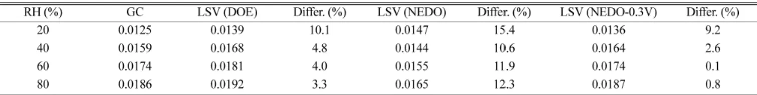
Anode애 수소, cathode에 아르곤을 200 ml/min 유속으로 유입하 면서 cathode 출구의 가스 중 수소의 농도를 상대습도에 따라 측정 해 수소 가스 투과도의 상대습도 의존성을 확인하였다(Fig. 2). 셀 온 도는 70oC, 입구 압력은 1.5 bar, 출구 압력은 대기압으로 하였다. GC와 LSV방법으로 측정한 수소투과도 원 데이터를 그대로 나타냈는데, 단위가 수소 농도 단위인 ppm과 수소투과전류밀도 단위인 mA/cm2 이어서 서로 비교하기가 어렵다. 그래서 GC와 LSV방법의 수소투과 측정결과를 막 면적당 수소투과속도(hydrogen crossover flux)로 환 산하여 Fig. 3에 비교하였다. 환산 시 압력이 낮아 수소를 이상기체 라 가정하고, 파라데이법칙을 이용했다. DOE의 LSV 방법은 GC방 법과 비슷하나 NEDO 방법은 차이가 있다. Table 2에 나타냈는데 DOE의 LSV 방법은 RH 20%를 제외하고 모두 GC방법과 5%이하의 차이를 보이나, NEDO 방법은 GC방법과의 차이가 모두 10% 이상 이다. 수소투과전류밀도(Hydrogen Crossover Current Density, HCCD) 를 결정하는 NEDO방법은 0.4 V에서 0.5 V 사이의 선을 외삽하여 0 V에서 전류 값으로 정하기 때문에 0.4 V에서 0.5 V 사이의 선의 기울기에 좌우되므로 정확도가 감소한 것으로 판단된다. 그래서 본 연 구에서는 NEDO의 HCCD결정방법을 DOE방법과 같이 0.3 V에서 전류밀도로 했을 때 정확도가 향상됨을 Fig. 4와 Table 2에서 볼 수 있다. 이 방법에 따르면 DOE 방법의 LSV방법보다 GC 값에 더 근 접한 수소투과속도를 얻을 수 있었다.
Fig. 2. Hydrogen permeability data by (a) GC (b) LSV by DOE method (c) LSV by NEDO method.
Fig. 3. Comparison of hydrogen fluxes measured by GC and LSVs (HCCD).
Table 2. Comparison of hydrogen flux(mL/min*cm2) measured by GC and LSVs
RH (%) GC LSV (DOE) Differ. (%) LSV (NEDO) Differ. (%) LSV (NEDO-0.3V) Differ. (%)
20 0.0125 0.0139 10.1 0.0147 15.4 0.0136 9.2
40 0.0159 0.0168 4.8 0.0144 10.6 0.0164 2.6
60 0.0174 0.0181 4.0 0.0155 11.9 0.0174 0.1
80 0.0186 0.0192 3.3 0.0165 12.3 0.0187 0.8
3-3. 온도에 따른 수소투과도 변화 비교
수소투과계수의 온도 의존성을 실험한 결과를 Fig. 5에 나타냈다.
온도가 상승함에 따라 수소투과도가 증가함을 볼 수 있다. 두 측정 값을 정확하게 비교할 수 있게 수소투과계수(Hydrogen permeability coefficient)를 계산하여 Fig. 6에 나타냈다. 수소투과 플럭스는 계산
과정에 고분자막의 두께와 수소 압력은 들어가지 않은 값들이어서 고분자막의 두께와 가스 압력을 고려한 수소투과 계수가 막의 특성을 동일 조건에서 비교할 때 사용된다. 고분자막에서 가스 투과계수를 Barrer 단위(1 Barrer = 10-10 cm3/(sec·cm·cmHg))를 사용하기도 하 나 연료전지 분야에서는 Fig. 6과 같은 ml/(min·m·Pa) 단위를 많이 사용해서[11,12] DOE LSV 방법과 GC방법의 수소투과계수를 이 단위로 비교하였다. 온도가 상승함에 따라 수소투과계수가 상승하 고 있고, DOE의 LSV 방법과 GC방법을 비교한 결과 차이가 5%이 내의 유사한 결과를 나타냈다.
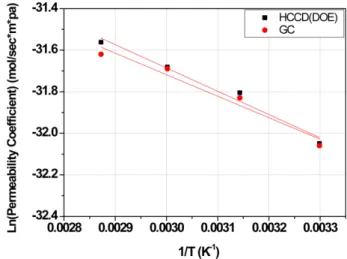
수소투과계수의 활성화에너지를 구하기 위해 아레니우스 플롯을 Fig. 7에 나타냈다. 기울기에 의한 수소투과 활성화 에너지 값은 LSV 방법과 GC방법 각각 8.61, 9.32 kJ/mol(약 7.0%차이)로, DOE 의 LSV 방법과 GC방법이 비교적 잘 맞음을 온도변화에 따른 수소 투과계수 변화 실험에서도 확인하였다.
4. 결 론
전기화학적으로 수소투과도를 측정하는 방법의 정확성을 확인하 기 위해 GC 방법을 다음과 같이 비교하였다. 본 실험 범위에서는 Fig. 5. Change of hydrogen permeability according to temperature
measured by (a) GC (b) DOE LSV.
Fig. 6. Change of hydrogen permeability coefficient according to temperature variation.
Fig. 7. Comparison of Arrhenius plots from data measured by GC and LSVs (DOE).
Fig. 4. Correctness increase of NEDO LSV method by determin- ing HCCD at 0.3 V.
수소투과도를 정확하게 측정할 수 있는 GC에 의한 수소투과도 측정 값이 기준이 되었다. 수소투과 플럭스와 수소투과계수로 GC 측정값 과 LSV 측정값을 환산하여 비교하였다. 일정온도에서 상대습도 변 화에 따라 수소투과도를 측정해 비교했을 때, DOE LSV 방법이 GC 방법과 비교해 오차 범위 5%이하의 정확성을 보였으나 NEDO 방법은 10%이상의 오차를 나타냈다. NEDO 방법의 문제점은 외삽에 의해 수소투과전류밀도를 결정하는 방법에서 오차가 많이 발생하였다.
DOE방법과 같이 0.3 V의 전류 값으로 수소투과전류밀도를 결정했 을 때 오차는 감소하였다. 일정 습도에서 온도 변화에 따라 수소투 과계수를 DOE LSV 방법과 GC 방법을 측정해 비교했을 때 오차 범 위 5%이하의 정확성을 보였고 수소투과계수 활성화 에너지는 각각 8.61, 9.32 kJ/mol이었다.
감 사
본 연구는 산업통상자원부의 산업기술혁신사업(10067135)의 일 환으로 수행되었습니다.
References
1. Williams, M. C., Strakey, J. P. and Surdoval, W. A., “The U. S.
Department of Energy, Office of Fossil Energy Stationary Fuel cell Program,” J. Power Sources, 143(1-2), 191-196(2005).
2. Perry, M. L. and Fuller, T. F., “A Historical Perspective of Fuel Cell Technology in the 20th Century,” J. Electrochem. Soc, 149(7), S59-S67(2002).
3. Wilkinson, D. P. and St-Pierre, J., in: W. Vielstich, H. A. Gasteiger.
A. Lamm (Eds.). Handbook of Fuel Cell: Fundamentals Tech- nology and Applications, Vol. 3, John Wiley & Sons Ltd., Chiches- ter, England, 611-612(2003).
4. Wilson, M. S., Garzon, F. H., Sickafus, K. E. and Gottesfeld, S.
“Surface Area Loss of Supported Platinum in Polymer Electro- lyte Fuel Cells,” J. Electrochem. Soc., 140, 2872-2877(1993).
5. Knights, S. D., Colbow, K. M., St-Pierre, J. and Wilkinson, D.
P., “Aging Mechanism and lifetime of PEFC and DMFC,” J.
Power Sources, 127, 127-134(2004).
6. Luo, Z., Li, D., Tang, H., Pan, M. and Ruan, R., “Degradation
Behavior of Membrane-electrode-assembly Materials in 10-cell PEMFC Stack,” Int. J. Hydrogen Energy, 31, 1838-1854(2006).
7. Pozio, A., Silva R. F., Francesco, M. D. and Giorgi, L., “Nafion Degradation in PEFCs from End Plate Iron Contamination,”
Electrochim. Acta, 48, 1543-1548(2003).
8. Xie, J., Wood III, D. L., Wayne, D. N., Zawodinski, T. A., Atanassov, P. and Borup, R. L., “Durability of PEFCs at High Humidity Conditions,” J. Electrochem. Soc., 152, A104-A113(2005).
9. Curtin, D. E., Lousenberg, R. D., Henry, T, J., Tangeman, P. C.
and Tisack, M. E., “Advanced Materials of Improved PEMFC Performance and Life,” J. Power Sources, 131, 41-48(2004).
10. Collier, A., Wang, H., Yaun, X., Zhang, J. and Wilison, D. P.,
“Degradation of Polymer Electrolyte Membranes,” Int. J. Hydrogen Energy, 31, 1838-1854(2006).
11. Jeong, J. J., Jeong, J. H., Kim, S. H., Ahn, B. K., Ko, J. J. and Park, K. P., “Measurement of Hydrogen Crossover by Gas Chro- matograph in PEMFC,” Korean Chem. Eng. Res., 52(4), 425-429 (2014).
12. Lee, H., Kim, T. H., Sim, W. J., Kim, S. H., Ahn, B. K., Lim, T.
W. and Park, K. P., “Pinhole Formation in PEMFC Membrane After Electrochemical Degradation and Wet/dry Cycling Test,”
Korean J. Chem. Eng., 28, 487-491(2011).
13. Jeong, J. J., Jeong, J. H., Kim, S. H., Ahn, B. K., Ko, J. J. and Park, K. P., “Measurement of Hydrogen Crossover during PEMFC Operation,” Korean Chem. Eng. Res., 53(4), 412-416(2015).
14. Oh, S. H., Hwang, B. C., Lee, M. S., Lee, D. H., and Park K. P.,
“Comparison of Hydrogen Crossover Current Density by Analysis Method of Linear Sweep Voltammetry (LSV) in Proton Exchange Membrane Fuel Cells,” Korean Chem. Eng. Res., 56(2), 151-155 (2018).
15. U.S. Department of Energy and U.S. DRIVE Fuel Cell Techni- cal Team, “Protocols for Testing PEM Fuel Cells and Fuel Cell Components,” Multi-Year Research, Development and Demon- stration Plan, 2016 Fuel Cell Section.
16. Daido University, Ritsumeikian Univ., Tokyo Institute of Tech- nology, Japan Automobile Research Ins., “Cell Evaluation and Analysis Protocol Guidline,” NEDO, Development of PEFC Technologies for Commercial Promotion-PEFC Evaluation Project, January 30(2014).