Antisymmetric-Symmetric Mode Conversion of Ultrasonic Lamb Waves and Negative Refraction on Thin Steel Plate
Jin Woo Sung*,** and Young. H. Kim*✝
Abstract In this study, focusing of ultrasonic Lamb wave by negative refraction with mode conversion from antisymmetric to symmetric mode was investigated. When a wave propagates backward by negative refraction, the energy flux is antiparallel to the phase velocity. Backward propagation of Lamb wave is quite well known, but the behavior of backward Lamb wave at an interface has rarely been investigated. A pin-type transducer is used to detect Lamb wave propagating on a steel plate with a step change in thickness. Conversion from forward to backward propagating mode leads to negative refraction and thus wave focusing. By comparing the amplitudes of received Lamb waves at a specific frequency measured at different distance between transmitter and interface, the focusing of Lamb wave due to negative refraction was confirmed.
Keywords: Lamb Wave, Mode Conversion, Backward Propagating Wave, Negative Refraction, Veselago Lens
[Received: June 4, 2013, Revised: June 17, 2013, Accepted: June 18, 2013] *Department of Physics and Earth Science, Korea Science Academy of KAIST, Busan 614-822, Korea, **Current Address: Department Physics and Astronomy, Seoul National University, Seoul 151-742, Korea ✝Corresponding Author: [email protected]
ⓒ 2013, Korean Society for Nondestructive Testing
1. Introduction
There has been increasing interest on materials with negative refractive index [1].
Having negative refractive index means that a wave’s energy flux (or group velocity) is anti- parallel to its phase velocity in that material.
In these materials, interesting physical phenomena such as negative refraction appears [2]. After Horace Lamb provided theoretical background for the existence of negative-index materials[3], backward propagation of electro- magnetic and acoustic waves have been observed on many materials including metamaterials [4,5].
Backward propagation of Lamb wave, a type of plate wave, is well known both theoretically and experimentally. Lamb waves’ modes are determined by the solutions of Rayleigh-Lamb dispersion equation [6]. There are symmetric and antisymmetric modes of Lamb waves; in specific modes group velocity is negative, showing backward wave propagation. However, properties of Lamb waves at the interface of a plate with
step thickness change where forward propagation occurs on one side and backward propagation occurs on the other side was not well known until the recent research by Bramhavar et al.
[7]. They observed that Lamb wave originated from a point source focuses in another media, which is called Velelago lens effect [8]. They used a plate with two parts with different thicknesses such that forward-propagating symmetric mode is converted to backward- propagating symmetric mode at the selected frequency.
Jeong Ki Lee et al. showed that Lamb wave generated by a point source perpendicular to a side of an isotropic plate includes A
1mode, an antisymmetric mode, dominantly. So, negative refraction produced by antysimmetric incident wave would enhance efficiency of experiment and practicality of backward propagating waves.
On a plate with appropriate thickness, a
forward-propagating antisymmetric Lamb wave
would convert into a backward-propagating
symmetric Lamb wave, and the symmetric wave
would focus due to Veselago lens effect.
In this study, we have observed conversion of antisymmetric Lamb wave into symmetric Lamb wave with negative refraction resulting in Velelago lens effect on a steel plate with a step change in thickness.
2. Theoretical Background
2.1 Dispersion Curve of Lamb Wave on Infinite Isotropic Plane
When a longitudinal wave propagating in a solid media enters aslant to an interface with fluid or vacuum, partial conversion into transverse wave occurs, resulting in the propagation of Lamb wave, a combination of longitudinal and transverse waves. Lamb waves can be classified into two types in which the vertical displacement is either symmetric or antisymmetric with respect to the center of the plate’s thickness. Symmetric and antisymmetric Lamb waves are further divided into various modes depending on wavelengths and frequencies.
Applying appropriate boundary conditions to the wave equation of elastic waves on infinite isotropic plate, the dispersion equation of Lamb wave is:
tan
tan
±
(1)
where the exponent is +1 for symmetric modes and -1 for antisymmetric modes. n=c
t/c
l, ν=ωh/π c
t, and s=c
t/c
x=c
tk/ω in which h is the thickness of the plate, c
lis the speed of longitudinal waves, ct is the speed of transverse waves, c
xis phase velocity of Lamb wave, k is wavenumber, and ω is the angular frequency.
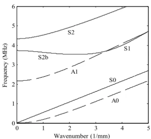
Fig. 1 shows some solutions of the Rayleigh-Lamb dispersion equation (Eq. (1)) for steel plate, where longitudinal speed is 5690 m/s and transverse speed is 3240 m/s. Since phase velocity is calculated ω/k and group velocity is
0 1 2 3 4 5
0 1 2 3 4 5 6
Wavenumber (1/mm)
Frequency (MHz)
S2b
A1 S2
S0 A0
S1
Fig. 1 Dispersion curve of some modes of Lamb wave on a steel plate 0.78 mm thick. Lamb wave propagates backwards in S2b mode.
dω/dk, we can determine phase velocity from the slope of the line connecting the origin and the point on a dispersion curve, whereas group velocity is the slope of the tangent at that point from Fig. 1.
Using this method, we can see that for a part of S
1mode, group velocity of Lamb wave has negative value. This mode is related to S
2mode by an imaginary loop, so this is called S
2bmode[11]. In this mode, Lamb wave propagates backwards.
2.2 Negative Refraction and Veselago Lens
Refraction occurs when a wave enters a media with refractive index difference.
Especially, if a wave enters a media with negative refractive index, negative refraction occurs, in which the incident wave and the refracted wave is on the same side of the normal line as in Fig. 2(a).
If the wavenumbers of incident and refracted
waves are equal, incidence and refraction angles
are equal by Snell’s law. This is also true for
negative refraction. Thus if the wavenumber
does not change when negative refraction occurs
over straight line, a wave generated from a
Fig. 2 (a) Incident and refracted waves are on the same side of the normal in negative refraction. (b) Negative refraction leads to Veselago lens effect, where waves refocus.
Fig. 3 Steel plate used in experiments, each part 5 centimeters long and wide.
0 0.5 1 1.5 2
2 2.1 2.2 2.3 2.4 2.5 2.6
Wavenumber (1/mm)
Frequency (MHz)
h1 = 0.78 mm (A1) h2 = 1.25 mm (S2b)
Fig. 4 Dispersion curve of parts overlapped, intersecting at 2.25 MHz frequency and 0.93 mm-1 wavenumber.
point source refocuses symmetrically on the other side of the interface as in Fig. 2(b). Since a wave is focused similarly to a lens, this effect is called Veselago lens effect after its proposer.
Frequency and wavenumber of Lamb wave depends on the thickness of a plate. Thus by changing the thickness, mode conversion can occur without change in frequency.
We tried to confirm negative refraction indirectly by observing Veselago lens effect while A
1mode Lamb wave generated at
2.25 MHz is converted into S
2bmode. If the thickness of steel plate is h
1= 0.78 mm on one side and h
2= 1.25 mm on the other side (Fig.
3), A
1mode and S
2bmode intersects at 2.25 MHz frequency and 0.93 mm
-1wave- number(Fig. 4). Antisymmetrical interface as in Fig. 3 was intentionally designed to reduce reflection at the interface, since Lamb wave is converted from antisymmetric mode to symmetric mode.
3. Experiment
We manufactured a steel plate with dimensions 100×200×0.78/1.25. On the 0.78 mm thick side, we generated Lamb wave pulses with 2.25 MHz ultrasonic transducer (diameter 12.7 mm) connected to a pulser. To generate A
1mode Lamb wave selectively using oblique incidence method, we put an acrylic wedge with 10.8° incidence angle between the transducer and the plate. On the 1.25 mm thick side, we obtained refracted signal with pin-type transducer held perpendicular to the plate by a specially designed equipment, and connected to a digital oscilloscope. During the experiment, the flat side of the steel plate was faced downwards.
To prevent changes in the contact state of the pin-type transducer, we moved the transmitter as well as the acrylic wedge instead of the receiver during each experiment set. In all cases, the transmitter and the receiver was located on the axis of symmetry of the plate.
There were five experiment sets, in which the receiver was located 30, 35, 40, 45, and 50 mm from the interface. For each experiment set, we moved the transmitter 20 mm to 80 mm from the interface with 5 mm step and saved waveforms.
We tried to generate A
1mode with oblique
incidence method, but since conversion into
modes other than S
2bcan occur during the
refraction. Thus we performed FFT (fast Fourier
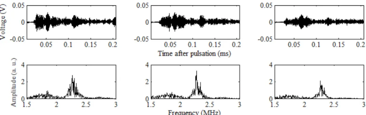
Fig. 5 (a) Original waveform of Lamb wave received. (b) FFT results over entire waveforms. The distance of transmitter from interface is 15 mm (left), 30 mm (center), 45 mm (right). The distance of receiver from interface is 3 cm for all three experiments.
transform) on the saved waveform to select 2.25 MHz component only.
It is possible that waves reflected at the ends of the plate are detected. We have experimentally determined that first signal arrives 15 μs after the trigger and the reflected wave arrives 115 μs after the trigger at the receiver. We performed FFT for signal between 15 μs and 115 μs after the trigger, and analyzed the magnitude of the largest amplitude around 2.25 MHz.
4. Result and Discussion
Fig. 5(a) shows original waveforms received by the pin-type transducer 30 mm from the interface. Although we used oblique transmission method, Lamb wave dispersed into various modes as it passed through interface. Theoretical calculation indicates that S
2bmode wave arrives 60 μs after pulsation. In fact, we observe largest amplitude of Lamb wave at 60 μs. S
2bmode has slower group velocity compared to A
0, S
0, and A
1modes, so they arrive faster, before 60 μs. In Fig 5(a), they arrive around 30 μs.
From Fig. 5(a), we see that Lamb waves including S
2bmode arrives later as the receiver moves farther away from the interface. However, Lamb wave received at 60 μs can include
reflected modes other than S
2bmode, so we extracted 2.25 MHz component using FFT.
Intensity of a wave generated from a point source decreases inversely proportional to the distance from the source, so as the transmitter moves away from the interface, received Lamb wave must decrease in amplitude. However, if Veselago lens effect occurs due to negative refraction, the intensity of the signal should either increase or mildly decrease at a special configuration. This occurs when the transmitter and the receiver are located the same distance away from the interface due to the design of the plate.
In Fig. 5(b), we see that the intensity of the 2.25 MHz Lamb wave component is larger when the transmitter is 30 mm away compared to 15 mm away from the interface. For this case, we can confirm that as A
1mode Lamb wave was converted into S
2bmode as it propagated into the part of the plate with differing thickness, negative refraction occurred, resulting in Veselago lens effect.
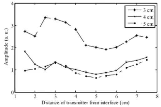
Fig. 6 shows amplitude of 2.25 MHz
component of received Lamb wave at various
configurations of transducers. The shapes of the
curves are generally U-shaped, but there are
bumps sticking up when the transmitter is
30-50 mm away from the interface, when the
1 2 3 4 5 6 7 8 0
1 2 3 4
Distance of transmitter from interface (cm)
Amplitude (a. u.)
3 cm 4 cm 5 cm
Fig. 6 Peak values of FFT results classified by distance of receiver from interface.