Field-in-Field Technique을 이용한 두경부암의 접합부위 선량개선에 관한 고찰
고려대학교 구로병원 방사선종양학과
김선명ㆍ이영철ㆍ정덕양ㆍ김영범
목 적: 두경부암의 치료에 있어 상부 두경부의 양측면조사면과 하경부의 전방조사면의 접합부위에 균등한 선량을 조사하는 것은 매우 중요하다. 접합부위의 선량분포개선을 위하여 하경부 전방조사면의 치료시 Field-in-Field technique을 이용하여 부 족선량(under dose)과 초과선량(over dose)으로 인한 선량불균등을 개선하고 일반치료와의 비교를 통하여 두경부암치료에 적 용하고자 한다.
대상 및 방법: 상부 두경부의 양측면 조사시 빔의 확산으로 일어나는 입사점과 출사점의 선량차이를 알아보기 위하여 인체 모형팬톰을 이용하였다. 인체모형팬톰을 전산화단층촬영하고 전산화치료계획에서 관심점의 선량비교를 시행하였고, 하경부 접합부위의 선량비율을 계산하여 이를 보정하였다. 조사면 접합부위의 선량분포를 알아보기 위하여 하경부의 접합부위에 저 감도 필름을 놓고 일반적인 치료인 상부 두경부의 양측면조사와 하경부의 전방조사시 선량분포를 측정하였다. 또한, 상부 두 경부 양측면 조사에 따른 빔의 확산을 고려한 Field-in-Field technique을 이용하여 하경부 전방조사를 할 때의 접합부위의 선 량분포 차이를 측정하여 비교하였다. 접합부위의 관심점 선량을 알아보기 위하여 열형광선량계를 이용하여 인체모형팬톰내 의 관심점에서의 선량변화를 비교, 분석하였다.
결 과: 전산화치료계획에서 하경부의 접합부위에 Field-in-Field technique을 적용하여 치료계획시 상부 두경부 양측면 조사와 선량합성을 한 경우 부족선량 영역의 선량이 4.7∼8.65% 이상 증가하였다. 초과선량 영역의 선량도 2.75∼10.45% 감소하였 다. 또한, 저감도 필름을 이용한 측정에서는 부족선량영역에서 11.3% 증가, 초과선량영역에서 5.3% 감소한 것으로 나타났다.
열형광선량계를 이용한 관심점선량측정에서도 Field-in-Field technique 적용시 부족선량을 최소 7.5%에서 최대 17.6%까지 보 정해주는 것으로 나타나 불균등한 선량분포를 개선할 수 있었다.
결 론: 전산화치료계획시 빔의 확산을 고려한 Field-in-Field technique을 적용하면 접합부위의 선량보정을 통해 냉점(cold spot)과 온점(hot spot)을 줄일 수 있었으며 특히, 빔의 확산에 따른 입사점의 부족선량을 보정할 수 있었다. 본 실험을 통해 Field-in-Field technique의 임상적용시 경부임파절의 저선량으로 인한 임파절전이에 대한 위험도를 감소시킬 수 있을 것으로 사료된다.
핵심용어: 접합부위, 빔확산, 선량분포
이 논문은 2008년 12월 12일 접수하여 2009년 3월 20일 채택되었음.
책임저자:김영범, 고려대학교 구로병원 방사선종양학과 Tel: 02)2626-1387, Fax: 02)2626-1399 E-mail: [email protected]
서 론
두경부암(head and neck cancer)의 일반적인 치료는 상부 두경부 양측면조사(bilateral port)와 하경부의 전방조사(ante- rior neck port) 치료이다.1) 비대칭 콜리메이터(collimator)를 이용한 치료방법은 이분 조사면(half beam)을 만드는데 효과 적이다.2) 이분 조사면은 임상에서 방사선의 방향이 다른 두 조사면을 인접시켜 조사하는데 빈번히 사용되는 조사방법으 로 특히 전 두경부를 조사하는 두경부 종양의 방사선치료에 서 상부 두경부의 양측면조사와 하부 경부의 전방조사하는
경우에 두 조사면을 일치시키는 방법으로 유용하게 사용할 수 있다.3) 하지만 하경부의 임파절 전이가 많은 경우 조사면 의 크기가 증가하고 이분 조사면의 콜리메이터가 열린부분 의 출사점에서 빔의 확산에 따른 선량의 불균등으로 인해 하 경부만을 이분조사면을 사용하고 있다. 이러한 경우 두경부 조사의 방사선치료에서 이 두 조사면의 접합부에는 양측면 조사시 빔(beam)의 확산으로 인하여 선량의 불균등이 나타 난다. 방사선치료에 있어서 치료부위내의 균등한 선량분포는 환자의 치료효과를 증대시키고 장해발생을 최소화하는 중요 한 인자이다.4) 최근 3차원 입체조형치료(3D conformal radia- tion therapy)나 세기변조방사선치료(intensity modulated ra- diation therapy, IMRT)의 발달로 최적화된 치료계획을 세울 수 있게 되었다.5) 하지만 여러 여건상 아직도 양측면 조사의 치료를 받고 있는 환자가 상당수 있다. 양측면 조사 치료시
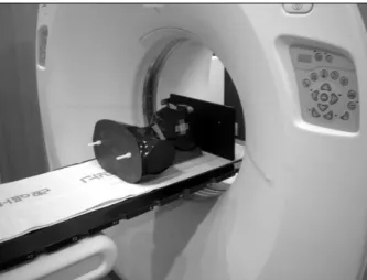
Fig. 1. The image of CT scan for RANDO phantom.
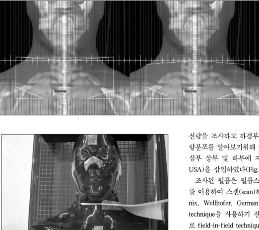
Fig. 2. Computer planning of oropharynx and lower neck. (A) Oropharynx plan, (B) Anterior lower neck plan.
Fig. 3. The points of dose calculation.
하였다.8) 본 연구에서는 두경부암의 일반적인 치료시 양측면 조사면의 빔의 확산을 계산하고 이를 하경부 전방조사시 3개 의 조사면으로 구분한 Field-in-Field technique을 사용하여 치료계획을 수립하였다. Isocenter 하경부의 치료중심에서 선 량이 부족한 냉점(cold spot)과 과선량지점인 온점(hot spot) 의 선량을 계산하고 이를 전산화치료계획시 Field-in-Field
1. 전산화 치료계획
본원에서 사용하고 있는 CT simulator (BrightSpeed Elite, GE)를 이용하여 인체모형팬톰(RANDO phantom)을 촬영하 였다(Fig. 1). 촬영된 영상을 이용하여 가상의 CTV (clinical target volume, CTV)를 설정하고 Fig. 2에서 보는 바와 같이
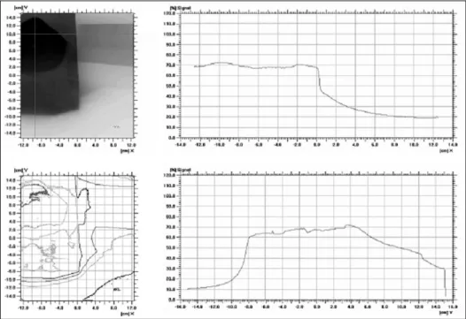
Fig. 5. The image of set-up for verification film.
Fig. 4. Supraclavicular field shaped by a multileaf collimator.
구강인두암(oropharynx cancer)을 가정하여 상부두경부 양측 면조사로 치료계획을 수립하였고 하경부의 임프절은 전방조 사로 치료계획을 수립하였다.
사용된 선형가속기는 Clinac-iX (Varian, USA)로 6 MV 광 자선(photon beam)이 사용되었다. 치료계획용컴퓨터(Eclipse, Varian, USA)에서 하경부의 전방조사는 먼저 중심축(isocen- ter)에서 측면 조사면의 Y1의 길이만큼 이동하여 표면-선원 간 거리(Source-Skin distance, SSD)를 100 cm으로 하여 계획 하였다. 이때 측면 조사면의 빔의 확산을 실제 3차원 재구성 된 이미지에 나타나게 하여 냉점(cold spot)과 온점(hot spot) 의 좌표를 설정한다(Fig. 3). 치료 조사면이 결정되면 중심점 과 냉점, 온점의 세지점(3 points) 선량을 계산하고 이를 하 경부의 치료 시 3개의 조사면에 선량비율(field weight)로 적 용하여 계산한다(Fig. 4).
2. 저감도 필름을 이용한 선량측면도(dose profile) 전산화 치료계획에 의하여 상부두경부에 200 cGy의 처방
선량을 조사하고 하경부에 200 cGy를 조사하였다. 이때, 선 량분포를 알아보기위해 인체모형팬톰의 접합면 중심부와 중 심부 상부 및 하부에 저감도 필름(X-Omat V-film, Kodak, USA)을 삽입하였다(Fig. 5).
조사된 필름은 필름스캐너(Dosimetry Pro, VIDAR, USA) 를 이용하여 스캔(scan)하였으며 I'mRT MatriXX (Scanditro- nix, Wellhofer, German)로 분석하였다. 먼저 field-in-field technique을 사용하기 전의 방법으로 조사하고 같은 방법으 로 field-in-field technique을 사용하여 치료시 조직내의 선량 분포를 비교하였다(Fig. 6).
3. 관심점 선량
컴퓨터치료계획상 접합부 상부의 3개 지점에서의 포인트 선량(point dose)을 계산하였고 실제 열형광선량계(Harshaw 5500)를 이용하여 같은 세 지점의 선량을 측정하였다. 측정 은 field-in-field technique 사용 전, 후로 하여 비교하였으며 온점과 냉점의 선량이 어느 정도 보정되는지 측정하였다. 열 형광선량계 소자는 표면에서 1.5 cm 깊이의 세지점에 위치 시켰다(Fig. 7, 8).
결 과
전산화 치료계획시 양측면 조사면(bilateral port)의 빔의 확산을 고려할 경우 표면에서 1.5 cm 깊이의 기준점(refer- ence point)을 측정점으로 하여 입사점(entrance point)에서는 9.5%의 선량이 부족한 것으로 나타났으며 출사점(exit point) 에는 17.0%의 선량이 과조사 되는 것으로 나타났다. 이를 보 정하기 위해 하경부치료시 3개의 조사면 선량비율(field weight)을 1.03:1.12:0.85 (중심축(center):상부(upper):하 부(lower))로 조절하여 조사하였다.
전산화 치료계획 시 Field-in-Field technique의 적용전후의
Fig. 8. The image of TLD dosimetry.
Fig. 7. Three points of measurement used TLD.
Fig. 6. Dose profile measured by low density film.
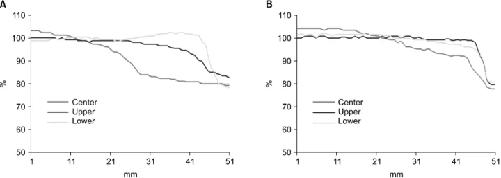
선량분포(dose profile)를 보면 Fig. 9에서 보는 바와 같이 적 용전에는 중심부에서 측방향으로 3 cm 지점의 선량은 상부 에서 5.35%의 저선량(under dose)을 보였고 하부에서는 3.7%
의 초과선량을 보였으며, 5 cm 지점의 선량은 상부에서 25.9%의 저선량(under dose)을 보였으며 하부에서는 6.2%의 초과선량(over dose)이 발생했다. Field-in-Field technique 적 용시는 Fig. 10에서 보는 바와 같이 3 cm 지점의 선량은 중 심부에 비해 상부에서 0.65%의 저선량과 하부에서 0.95%의 초과선량을 보였다. 5 cm 지점에서의 선량은 상부에서 17.25%의 저선량과 하부에서 4.25%의 저선량이 조사된 것으
로 나타났다.
Field-in-Field technique 적용전 저감도 필름을 이용한 선 량측면도(dose profile) 측정에서 중심축에서 측방향으로 4 cm 떨어진 지점의 선량은 중심부에 비해 상부에서 18.8% 저 선량, 하부에서 2.7% 초과선량이 조사되는 것으로 나타났으 며 적용후에는 상부에서 7.5% 저선량, 하부에서 2.6% 부족선 량이 조사되는 것으로 나타났다.
또한, 인체모형팬톰내 3개의 관심점에 대해 컴퓨터치료계
Fig. 9. Comparison of dose line profile with and without field-in-field technique in computer planning. (A) Dose line profile of field junction (not used field-in-field technique). (B) Dose line profile of field junction (used field-in-field technique).
Fig. 10. Comparison of dose line profile with and without field-in-field technique in film scan. (A) Dose profile of field junction (not used field-in-field technique). (B) Dose line profile of field junction (used field-in-field technique).
Technique Point RTP dose (cGy)
TLD dose (cGy)
Conventional A 48.2 33.0
B 47.5 33.8
C 47.1 34.2
Field-in-Field A 50.6 48.0
B 56.4 58.2
C 62.3 69.4
Table 1. Measured dose of 3 points used TLD with conven- tional technique compared with Field-in-Field technique 획상에서 계산된 선량은 Field-in-Field technique 사용전
A-point에는 48.2 cGy, B-point에는 47.5 cGy, C-point에는 47.1 cGy로 측정되었다. Field-in-Field technique 사용후에는 A-point에는 50.6 cGy, B-point에는 56.4 cGy, C-point에는 62.3 cGy로 측정되었다.
실제 열형광선량계(thermoluminescence dosimeter, TLD)를 이용한 선량비교에서는 Field-in-Field technique 사용 전 A- point에는 33 cGy, B-point에는 33.8 cGy, C-point에는 34.2 cGy로 측정되었다. Field-in-Field technique 사용후에는 A- point에는 48 cGy, B-point에는 58.2 cGy, C-point에는 69.4 cGy로 측정되었다(Table 1).
의 조사면이 입사되도록 하는 방법 등이 사용되고 있다. 하 지만 이 또한 환자 테이블(couch)을 이동하거나 이분조사면 치료 시에는 조사면의 크기가 작아야 하는 등의 제한점을 가 지고 있어 일반적인 치료인 양측면조사와 전방조사의 병행 시 Field-in-Field technique을 이용하여 접합면의 선량불균등 을 개선할 수 있었다.
양측면 조사 시 입사면에는 SAD (source-axis distance) set-up의 특성상 치료범위에서 제외되는 냉점(cold spot)이 생 기고 반대쪽의 출사면에는 빔의 확산으로 인한 온점(hot spot)이 생기게 된다. 이러한 선량불균등을 Field-in-Field technique을 사용하게 됨으로써 냉점의 선량은 최대 11.3%
증가시킬 수 있었으며 온점의 선량은 5.3%가량 줄일 수 있었 다.
냉점의 선량이 온점의 선량에 비해 상대적으로 많이 보정 되는 것은 빔의 확산에 따른 영향으로 입사점부분의 냉점이 출사점부분의 온점에 비해 선량불균등이 심하기 때문인 것 으로 생각된다. 이러한 냉점의 발생으로 인한 선량불균등 또 한 열형광선량계를 이용한 실험을 통해서 일반적인 치료시 33.0∼34.2 cGy인 관심점의 선량을 Field-in-Field technique 을 사용함으로써 48.0∼69.4 cGy까지로 보정해 주는 것을 확 인할 수 있었다.
본 실험을 통해 두경부암의 일반적인 빔의 확산에 따른 입 사점의 선량부족과 출사점의 선량과다를 보정할 수 있음을 알 수 있었으며 중심부보다는 주변부로 갈수록 심화되는 선
참고문헌
1. Duan J, Shen S, Spencer SA, et al.: A dynamic supraclavicular field-matching technique for head and neck cancer patients treated with IMRT. Int J Radiat Oncol Biol Phys 2004;
60:959-972
2. 김정기, 김기환, 오영기 등: 두경부 방사선치료시 접합 조사면 의 선량분포. 의학물리 2001;12:161-169
3. Williamson TJ: A technique for matching orthogonal megavoltage fields. Int J Radiat Oncol Biol Phys 1979;5:
111-118
4. 김보겸, 이제희, 정치훈, 박흥득: 전뇌 치료 시 Field-in-Field Technique 적용에 관한 고찰. 대한방사선치료학회지 2005;17:
9-17
5. Purdy JA: Advances in three-dimensional treatment planning and conformal dose delivery. Semi Oncol 1997;24:655-671 6. Chiang TC, Culbert H, Wyman B, et al.: The half field
technique of radiation therapy for the cancers of head and neck. Int J Radiat Oncol Biol Phys 1979;5:1899-1901 7. Sohn JW, Schell MC, Dass KK, et al.: Uniform irradiation of
the craniospinal axis with a penumbra modifier and an asmmetric collimator. Int J Radiat Oncol Biol Phys 1994;29:
187-190
8. Kron T, Barnes K, O'Brien P: Multicentre dosimetric comparison of photon-junctioning techniques in head and neck radiotherapy. Australasian Radiology 2003;47:289-294
Abstract
Field-in-Field Technique to Improve Dose Distribution in the Junction of the Field with Head & Neck Cancer
Seon Myeong Kim, Yeong Cheol Lee, Deok Yang Jeong, Young Bum Kim Department of Radiation Oncology, Korea University Guro Hospital, Seoul, Korea
Purpose: In treating head and neck cancer, it is very important to irradiate uniform dose on the junction of the bilateral irradiation field of the upper head and neck and the anterior irradiation field of the lower neck. In order to improve dose distribution on the junction, this study attempted to correct non uniform dose resulting from under dose and over dose using the field-in-field technique in treating the anterior irradiation field of the lower neck and to apply the technique to the treatment of head and neck cancer through comparison with conventional treatment.
Materials and Methods: In order to examine dose difference between the entry point and the exit point where beam diffusion happens in bilateral irradiation on the upper head and neck, we used an anthropomorphic phantom.
Computer Tomography was applied to the anthropomorphic phantom, the dose of interest points was compared in radiation treatment planning, and it was corrected by calculating the dose ratio at the junction of the lower neck.
Dose distribution on the junction of the irradiated field was determined by placing low-sensitivity film on the junction of the lower neck and measuring dose distribution on the conventional bilateral irradiation of the upper head and neck and on the anterior irradiation of the lower neck. In addition, using the field-in-field technique, which takes into account beam diffusion resulting from the bilateral irradiation of the upper head and neck, we measured difference in dose distribution on the junction in the anterior irradiation of the lower neck. In order to examine the dose at interest points on the junction, we compared and analyzed the change of dose at the interest points on the anthropomorphic phantom using a thermoluminescence dosimeter.
Results: In case of dose sum with the bilateral irradiation of the upper head and neck when the field-in-field technique is applied to the junction of the lower neck in radiation treatment planning, The dose of under dose areas increased by 4.7∼8.65%. The dose of over dose areas also decreased by 2.75∼10.45%. Moreover, in the measurement using low-sensitivity film, the dose of under dose areas increased by 11.3%, and that of over dose areas decreased by 5.3%. In the measurement of interest point dose using a thermoluminescence dosimeter, the application of the field-in-field technique corrected under dose by minimum 7.5% and maximum 17.6%. Thus, with the technique, we could improve non‐uniform dose distribution.
Conclusion: By applying the field-in-field technique, which takes into account beam divergence in radiation treat- ment planning, we could reduce cold spots and hot spots through the correction of dose on the junction and, in particular, we could correct under dose at the entry point resulting from beam divergence. This study suggests that the clinical application of the field‐in‐field technique may reduce the risk of lymph node metastasis caused by under dose on the cervical lymph node.
Key words: junction, beam divergence, dose distribution