Vol. 24, No. 4 (2014)
180
Simultaneous Synthesis and Consolidation of Nanostructured MoSi
2-NbSi
2Composite by High-Frequency Induction Heated Sintering
and Its Mechanical Properties
Hyun-Su Kang and In-Jin Shon †
Division of Advanced Materials Engineering, Research Center of Advanced Materials Development, Chonbuk National University, 664-14 Deokjin-dong 1-ga, Deokjin-gu, Jeonju, Jeonbuk 561-756, Korea
(Received January 7, 2014 : Received in revised form March 26, 2014 : Accepted March 26, 2014)
Abstract
The current concern about these materials (MoSi2 and NbSi2) focuses on their low fracture toughness below the ductile-brittle transition temperature.To improve the mechanical properties of these materials, the fabrication of nanostructured and composite materials has been found to be effective. Nanomaterials frequently possess high strength, high hardness, excellent ductility and toughness, and more attention is being paid to their potential application. In this study, nanopowders of Mo, Nb, and Si were fabricated by high-energy ball milling. A dense nanostructured MoSi2-NbSi2 composite was simultaneously synthesized and sintered within two minutes by high-frequency induction heating method using mechanically activated powders of Mo, Nb, and Si. The high-density MoSi2-NbSi2 composite was produced under simultaneous application of 80MPa pressure and an induced current. The sintering behavior, mechanical properties, and microstructure of the composite were investigated.The average hardness and fracture toughness values obtained were 1180 kg/mm2 and 3 MPa·m1/2, respectively. These fracture toughness and hardness values of the nanostructured MoSi2-NbSi2 composite are higher than those of monolithic MoSi2 or NbSi2.
Key words
composite, mechanical properties, sintering, nanostructured materials.1. Introdution
MoSi 2 and NbSi 2 have been investigated as potential materials for high-temperature structural applications and for use in the electronics industry. Their properties provide a desirable combination of a high melting temperature, high modulus, good oxidation resistance in air, a relatively low density, 1) and the ability to undergo plastic deform- ation above 1200 o C. 2) Combined with good thermal and electric conductivities, these properties have led to the utilization of MoSi 2 as a heating element material in high-temperature furnaces operating in air up to approxi- mately 1700 o C. 3,4) However, as in the case of many similar compounds, the current concern about these ma- terials(MoSi 2 and NbSi 2 ) focuses on their low fracture toughness below the ductile-brittle transition tempera- ture. 5-7) To improve the mechanical properties of these materials, the fabrication of a nanostructured material and
composite material 8-11) have been found to be effective.
As nanomaterials possess high strength, high hardness, excellent ductility and toughness, undoubtedly, more at- tention has been paid to their potential application. 12,13)
Recently, nanocrystalline powders have been produced by high-energy milling. 14,15) The sintering temperature of high-energy mechanically milled powder is lower than that of unmilled powder due to the increased reactivity, internal and surface energies, and surface area of the milled powder, which contribute to its so-called mech- anical activation. 16-18) The grain size in sintered materials becomes much larger than that in pre-sintered powders due to rapid grain growth during a conventional sintering process. Therefore, controlling grain growth during sin- tering is one of the keys to the commercial success of nanostructured materials. In this regard, the high-fre- quency induction-heated sintering(HFIHS) method, which can make dense materials within 2 minutes, has been
†
Corresponding author
E-Mail : [email protected] (I.-J. Shon, Chonbuk Nat'l Univ.)
© Materials Research Society of Korea, All rights reserved.
This is an Open-Access article distributed under the terms of the Creative Commons Attribution Non-Commercial License (http://creative-
commons.org/licenses/by-nc/3.0) which permits unrestricted non-commercial use, distribution, and reproduction in any medium, provided the
original work is properly cited.
shown to be effective in achieving not only rapid den- sification to near theoretical density, but also the prohib- ition of grain growth in nanostructured materials. 19-21)
This paper reports on the rapid synthesis and con- solidation of dense nanostructured MoSi 2 -NbSi 2 composite starting with high-energy ball-milled nanopowders. The mechanical properties and grain sizes of the resulting nanostructured MoSi 2 -NbSi 2 composite were also evaluated.
2. Experimental Procedures
Powders of 99.95 % pure molybdenum(< 10 µm, Aldrich Products), 99.5 % pure silicon( −325 mesh, Aldrich Pro- ducts), and 99.8 % pure niobium( −325 mesh, Alfa Pro- ducts) were used as starting materials. 0.5Mo, 0.5Nb, and 2Si powder mixtures were first milled in a high-energy ball mill(Pulverisette-5 planetary mill) at 250 rpm and for 10 h. Tungsten carbide balls(9 mm in diameter) were used in a sealed cylindrical stainless steel vial under an argon atmosphere. A charge ratio(ratio of ball mass to powder) of 30:1 was used. The grain size was calculated using Suryanarayana and Grant Norton’s formula 22) :
B r (B crystalline + B strain ) cos θ = kλ / L + ηsinθ (1) where B r is the full width at half-maximum(FWHM) of the diffraction peak after an instrumental correction;
B crystalline and B strain are the FWHM caused by the grain size and internal stress, respectively; k is a constant(with a value of 0.9); λ is the wavelength of the X-ray ra- diation; L and η are the grain size and internal strain, respectively; and θ is the Bragg angle. The parameters, B and B r , follow the Cauchy’s form with the relationship B = B r + B s , where B and B s are the FWHM of the broadened Bragg peaks and the standard Bragg peaks of the samples, respectively.
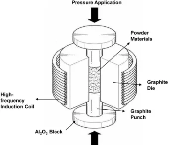
After milling, the powder was placed in a graphite die (outside diameter = 35 mm, inside diameter = 10 mm, and height = 40 mm), and then introduced into the induced current-activated sintering system, shown schematically in Fig. 1. The four major stages in the synthesis are as follows: evacuation of the system to 40 mtorr(stage 1), application of a uniaxial pressure of 80 MPa(stage 2), activation of an induced current, which was maintained
until densification was attained as indicated by a linear gauge measuring the shrinkage of the sample(stage 3), and cooling the sample to room temperature(stage 4). The samples were densified by heating to a sintering tempera- ture of 1200 o C with heating rate of 1000 o C/min. Tem- peratures were measured by a pyrometer focused on the surface of the graphite die. The process was carried out under a vacuum of 40 mtorr(5.3 Pa).
The relative densities of the sintered samples were measured by the Archimedes method. Microstructural information was obtained from product samples, which were polished and etched for 1 minute at room tempera- ture using a solution composed of HF(10 vol.%), HNO 3 (30 vol.%), and H 2 O(60 vol.%). Compositional and micro- structural analyses of the products were made through X- ray diffraction(XRD) and field emission scanning electron microscopy(FE-SEM) with energy dispersive X-ray an- alysis(EDAX). Vickers hardness was measured by per- forming indentations with a load of 5 kg and a dwell time of 15 s on the synthesized samples.
3. Results and Discussion
Fig. 2 shows SEM images of the raw powders used.
Nb and Si have angular shapes, while Mo has a round Fig. 1. Schematic diagram of the high-frequency induction-heated sintering apparatus.
Fig. 2. SEM images of raw materials: (a) Nb, (b) Mo, and (c) Si.
shape. XRD patterns of raw powders and milled 0.5Mo- 0.5Nb-2Si powders are shown in Fig. 3. In Fig. 3(d), only Mo, Nb, and Si peaks were observed, as marked.
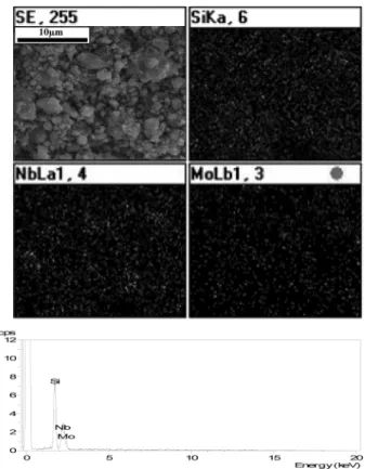
Therefore, it is obvious that no chemical reaction occurred between the component powders during milling. Never- theless, the peaks of the powders are significantly wide, suggesting that their grain sizes became very fine due to the milling. The average grain sizes of Mo, Nb, and Si measured by Suryanarayana and Grant Norton’s formula 22) were about 77, 25, and 16 nm, respectively. Fig. 4 shows a SEM image of milled powders, X-ray mapping, and EDS analysis. The milled powders have a very fine grain size and some agglomeration. In X-ray mapping, Mo, Nb, and Si distributed uniformly. In EDS, only Mo, Nb, and Si peaks were detected. The milling process is known to introduce impurities from the ball and/or con- tainer. However, in this study, peaks of Fe and W were not identified.
The interaction between these phases, i.e.,
0.5Mo + 0.5Nb + 2Si → 0.5MoSi 2 + 0.5NbSi 2 (2) is thermodynamically feasible, as shown in Fig. 5.
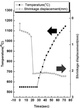
The variations in shrinkage displacement and tempera- ture of the surface of the graphite die upon heating
during the synthesis and densification of MoSi 2 -NbSi 2 composite are shown in Fig. 6. As the induced current Fig. 4. SEM image, X-ray mapping, and EDS of the milled 0.5Mo- 0.5Nb-2Si powder.
Fig. 5. Temperature dependence of the Gibbs free energy change by interaction of the 0.5Mo+0.5Nb+2Si.
Fig. 3. XRD patterns of raw materials: (a) Nb, (b) Mo, (c) Si, and
(d) milled 0.5Mo-0.5Nb-2Si powder.
was applied, the shrinkage displacement increased slowly with temperature up to 700 o C, and then abruptly in- creased. Fig. 7 shows the X-ray diffraction result of the sample heated to 1200 o C. The reactant peaks of Mo, Nb, and Si were not detected and only product peaks of MoSi 2 and NbSi 2 were observed. The abrupt increase in the shrinkage displacement at the ignition temperature is due to the increase in density resulting from the change
in the molar volume associated with the formation of MoSi 2 and NbSi 2 from the reactants(Mo, Nb, and Si) and the consolidation of the product.
The average grain size of MoSi 2 and NbSi 2 measured by Suryanarayana and Grant Norton’s formula 22) was about 168 and 110 nm, respectively. A FE-SEM image of the etched surface of the sample heated to 1200 o C under a pressure of 80 MPa is shown in Fig. 8. The micro- structure consists of nanophases in the FE-SEM image.
The corresponding relative density is 98 %. The role of the current during sintering and/or synthesis has been the focus of several attempts to provide an explanation for the observed sintering enhancement and the improved product characteristics. The role played by the current has been broadly interpreted by several groups. The effect has been explained by rapid heating due to Joule heating at contacts points, the presence of plasma in pores separating powder particles, and the intrinsic contribution of the current to mass transport. 23-26)
Vickers hardness measurements were made on polished sections of the MoSi 2 -NbSi 2 composite using a 5-kg load and 15-s dwell time. The calculated hardness value of the MoSi 2 -NbSi 2 composite was 1180 kg/mm 2 . This value re- presents an average of five measurements. Indentations with large enough loads produced median cracks around the indentations. The length of these cracks permits an estimation of the fracture toughness for the material. From the length of these cracks, fracture toughness values can be determined using the formula developed by Anstis et al., 27) which is
K IC = 0.016(E/H) 1/2 · P/C 3/2 (4) where E is Young’s modulus, H is the indentation hardness, P is the indentation load, and C is the trace length of the crack measured from the center of the Fig. 8. FE-SEM image of MoSi
2-NbSi
2composite sintered at 1200
oC.
Fig. 6. Variations of temperature and shrinkage displacement with heating time during synthesis and densification of the MoSi
2-NbSi
2composite.
Fig. 7. XRD patterns of the 0.5Nb-0.5Mo-2Si system heated at
1200
oC.
indentation. The modulus was estimated by the rule of mixtures for the 0.52 volume fraction of MoSi 2 and the 0.48 volume fraction of NbSi 2 using E(MoSi 2 ) = 204 GPa 28) and E(NbSi 2 ) = 362 GPa. 29) As in the case of hardness values, the toughness values were derived from the average of five measurements. The toughness value obtained by this method of calculation is 3 MPa·m 1/2 . These fracture toughness and hardness values of the nano- structured MoSi 2 -NbSi 2 composite are higher than those (fracture toughness; 2.58 MPa·m 1/2 hardness; 8.7 MPa) of the microstructured MoSi 2 30) or those(fracture toughness;
2.5 MPa·m 1/2 hardness; 876 kg/mm 2 ) of the nanostruc- tured NbSi 2. 7) A typical indentation pattern for the MoSi 2 - NbSi 2 composite is shown in Fig. 9(a). Typically, one to three additional cracks were observed to propagate from the indentation corner. A higher magnification view of the indentation median crack in the composite is shown in Fig. 9(b). This shows that the crack propagates in a deflective manner ( ↑). This is believed to suggest that NbSi 2 and MoSi 2 in the composite may deter the pro- pagation of cracks.
4. Summary
Mo, Nb and Si nanopowders were fabricated using high-energy ball milling for 10 h. Using the high-fre- quency induction-heated sintering method, a MoSi 2 -NbSi 2 composite was consolidated using the mechanically activated powders of 0.5Mo, 0.5Nb, and 2Si within two minutes. The relative density of the composite was 98 % for the applied pressure of 80 MPa. The average grain sizes of MoSi 2 and NbSi 2 in MoSi 2 -NbSi 2 composite sin- tered by HFIHS method were determined as 168 and 110 nm, respectively.
The average hardness and fracture toughness values obtained were 1180 kg/mm 2 and 3 MPa·m 1/2 , respectively.
These fracture toughness and hardness values of the nanostructured MoSi 2 -NbSi 2 composite are higher than those of monolithic MoSi 2 or NbSi 2 .
Acknowledgements
This research was supported by the Basic Science Re- search Program through the National Research Foundation of Korea(NRF) funded by the Ministry of Education, Science and Technology(No. 2012001300) and this work was supported by the Human Resources Development Program(No. 20134030200330) of the Korea Institute of Energy Technology Evaluation and Planning(KETEP) grant funded by the Korea government Ministry of Trade, industry and Energy.
References
1. A. K. Vasudevan, J. J. Petrovic, Mater. Sci. Eng., A 155, 1 (1992).
2. R. Mitra, Y. R. Mahajan, N. E. Prasad, W. A. Chiou, C.
Ganguly. Key Eng. Mater., 108-110, 11 (1995).
3. J. Milne, Instant Heat, Kinetic Metals Inc., Derby, Connecticut, (1985).
4. Y. S. Touloukian, R. W. Powell, C. Y. Ho, P. G. Klemens, Thermal Conductivity, IFI/Plenum, New York, (1970).
5. G. Sauthoff, Intermetallics, VCH Publishers, New York, (1995).
6. Y. Ohya, M. Hoffmann, G. Petzow, J. Mater. Sc. Lett., 12, 149 (2004).
7. I. Y. Ko, B. R. Kim, K. S. Nam, B. M. Moom, B. S. Lee and I. J. Shon, Met. Mater. Int., 15, 399 (2009).
8. I. J. Shon, I. Y. Ko, H. S. Kang, K. T. Hong, J. M. Doh and J. K. Yoon, Met. Mater. Int., 18, 115 (2012).
9. Y. Ohya, M. J. Hoffmann and G. Petzow, J. Am. Ceram.
Soc., 75, 2479 (1992).
10. S. K. Bhaumik, C. Divakar, A. K. Singh and G. S.
Upadhyaya, J. Mater. Sci. Eng., A 279, 275 (2000).
11. I. J. Shon, K. I. Na, J. M. Doh, H. K. Park and J. K.
Yoon, Met. Mater. Int., 19, 99 (2013).
Fig. 9. (a) Vickers hardness indentation and (b) median crack
propagation in the MoSi
2-NbSi
2composite.
12. H. S. Nalwa, Hanbook of Nanostructured Materials and Nanotechnology. Academic Press, Tokyo, (1996).
13. S. Berger, R. Porat and R. Rosen, Prog. Mater. Sci., 42, 311 (1997).
14. G. W. Lee and I. J. Shon, Korean. J. Met. Mater., 51, 95 (2013).
15. I. J. Shon, G. W. Lee, J. M. Doh and J. K. Yoon, Electron. Mater. Lett., 9, 219 (2013).
16. F. Charlot, E. Gaffet, B. Zeghmati, F. Bernard and J. C.
Liepce, Mater. Sci. Eng., A262, 279 (1999).
17. V. Gauthier, C. Josse, F. Bernard, E. Gaffet and J. P.
Larpin, Mater. Sci. Eng., A262, 117 (1999).
18. M. K. Beyer and H. Clausen-Schaumann, Chem. Rev.
105, 2921 (2005).
19. S. M. Kwak, H. K. Park and I. J. Shon, Korean. J. Met.
Mater., 51, 314 (2013).
20. I. J. Shon, S. L. Du, j. M. Doh and J. K. Yoon, Met.
Mater. Int. 19, 1041 (2013).
21. N. R. Kim, S. W. Cho, W. Kim and I. J. Shon, Korean.
J. Met. Mater., 50, 34 (2012).
22. C. Suryanarayana, M. Grant Norton, X-ray Diffraction A Practical Approach, Plenum Press, New York (1998).
23. Z. Shen, M. Johnsson, Z. Zhao and M. Nygren, J. Am.
Ceram. Soc., 85, 1921 (2002).
24. J. E. Garay, U. Anselmi-Tamburini, Z. A. Munir, S. C.
Glade and P. Asoka- Kumar, Appl. Phys. Lett., 85, 573 (2004).
25. J. R. Friedman, J. E. Garay. U. Anselmi-Tamburini and Z. A. Munir, Intermetallics, 12, 589 (2004).
26. J. E. Garay, J. E. Garay. U. Anselmi-Tamburini and Z. A.
Munir, Acta Mater., 51, 4487 (2003).
27. G. R. Anstis, P. Chantikul, B. R. Lawn and D. B.
Marshall, J. Am. Ceram. Soc. 64, 533 (1981).
28. A. K. Vasudevan and J. J. Petrovic, Mater. Sci. Eng., A 155, 1 (1992).
29. F. Chu, M. Lei, S. A. Maloy. J. J. Petrovic and T. E.
Mitchell, Acta mater.,44, 3035 (1996).
30. R. K. Wade and J. J. Petrovic, J. Am. Ceram. Soc. 75, 1682 (1992).