GPS 시스템의 C/A 부호 생성 알고리듬의 분석
장위*ㆍ서희종**
Analysis of Coarse Acquisition Code Generation Algorithm in GPS System
Wei Zhang*ㆍHee-Jong Suh**
요 약
본 논문에서는 민간용으로 사용되는 GPS 시스템의 C/A 부호(Coarse Acquisition Code)를 연구, 모의실험하 고, 분석하였다. 모의실험은 Matlab을 사용하였다. 실제의 GPS 신호를 해석하는 문제를 모의실험을 한 결과, 이 부호 문제의 융통성과 정확성을 확인할 수 있었다. 이의 방법의 응용으로 위성신호를 정확하게 추적할 수 있게 할 수 있고, 위성수신기의 성능을 향상시키는데 도움이 될 것이다.
ABSTRACT
In this paper, the coarse acquisition code (C/A code), for civil navigation, of the ranging codes for Global Positioning System (GPS) is studied, simulated and analyzed by using Matlab. We can see with the simulation results that the correctness of the method and feasibility, which is at simulation platform to further study on the real environment of GPS signal, can be confirmed. With using this results, we think, the complexity of tracking the satellite signal environment can be captured, and the performance of satellite receiver will be improved
키워드
GPS, C/A Code, P Code, Matlab GPS, C/A 코드, P 코드, Matlab
* 북경석유화공학원([email protected])
** 교신저자 : 전남대학교 전남통신공학과 ㆍ접 수 일 : 2016. 12. 28
ㆍ수정완료일 : 2017. 02. 13 ㆍ게재확정일 : 2017. 02. 24
ㆍReceived : Dec. 28 2016, Revised : Feb. 13, 2017, Accepted : Feb. 24, 2017 ㆍCorresponding Author : Hee-Jong Suh
Dept. of Electro. Comm. Eng., Chonnam Nat’l University Email : [email protected]
Ⅰ. INTRODUCTION
Global Positioning System (GPS) is a satellite- based positioning system, to users on a global scale to provide all-weather high-precision navigation, positioning and timing services. Ranging Code of GPS system can be divided into coarse acquisition code (C/A code) and precision code (P code), and the C/A Code is for civil navigation.
In this paper, we do the in-depth study of C/A code signal generated on the basis of principle, and the simulation implementation and analysis by using Matlab. This simulation results can confirm the correctness of the method and feasibility, which is at simulation platform to further study on the real environment of GPS signal, so that it can capture the complexity of tracking the satellite signal environment, and improve the performance of http://dx.doi.org/10.13067/JKIECS.2017.12.1.61
satellite receiver. This study is a very important part of practical significance.
This paper is organized as follows. In Section II the GPS C/A code signal structure is introduced. In Section III the GPS signal simulation and implementation is done by Matlab. Section IV is the conclusion.
Ⅱ. GPS C/ A Code Signal Structure
The GPS system have 21 work satellites and 3 in-orbit spare satellites, their equally disposition on six tracks. The satellite launches two kinds of frequencies which modulate with the pseudo-random code; L1=1575.42 MHz, L2=1227.6 MHz. The subscriber's equipment with surveys to several satellite distance method, determines the viewpoint the position. The GPS system can provide the three dimensional position continuously (longitude, latitude, highly), the three dimensional speed and the time, realizes the near real-time guidance localization. The dual-frequency launch is to supply the subscriber's equipment to eliminate the ionized layer to the dissemination the influence[1-2].
2.1 GPS signal frequency characteristics, modulation methods and their characteristics
The GPS signal contains two frequency components: link 1 (L1) and link 2 (L2). The canter frequency of L1 is at 1575.42 MHz and L2 is at 1227.6 MHz. These frequencies are coherent with a 10.23 MHz clock. These two frequencies can be related to the clock frequency as f1=1575.42 MHz=154×10.23 MHz and f2=1227.6 MHz=120×10.23 MHz.
These frequencies are very accurate as their reference is an atomic frequency standard. When the clock frequency is generated, it is slightly lower than 10.23 MHz to take the relativistic effect
into consideration. The reference frequency is off [5] by Hz, which corresponds to a fraction of − 4.4647× (−4.567× /10.23×). Therefore, reference frequency used by the satellite is 10.229999995433 MHz(10.23×∼4.567× ) rather than 10.23 MHz. When a GPS receiver receives the signals, they are at the desired frequencies.
However, the satellite and receiver motion scan produce a Doppler effect. The Doppler frequency shift produced by the satellite motion at L1 frequency is approximately ±5 KHz.
GPS signals have some salient features. Choice of carrier frequency of the two L band frequencies.
This is not just two frequencies selected. Interval between two frequencies for the 347.82MHz, equal L2 frequency of 28.3%, enough to make use of dual-frequency precise estimates of ionosphere delay (L1 and L2 frequency of the frequency ratio of 77/60 = 1.2833). Ionosphere delay broadly in line with frequency inversely proportional to the square, so on through the two frequency measurements can be calculated ionosphere delay, thereby eliminating the effects of ionosphere delay. However, ordinary single-frequency users can not capture the P code, should not measure the ionosphere delay, and must be made of ionosphere delay model, which there would be less accurate. Existing indirect "no code"
method can be dual-frequency ionosphere measurements. Non-code program will significantly reduce the signal to noise ratio (SNR), which requires the tracking loop bandwidth got a very narrow, and this job should not cause the receiver at high dynamic environment.
GPS satellite navigation message sent to users when using direct sequence spread spectrum technology, is about to send low bit rate to send the signal into a complex code, expand the scope of the signal spectrum and reduce the signal power density, enhanced data transmission and anti-jamming confidentiality [1].
2.2 GPS ranging code principle
The two GPS codes are called coarse acquisition (or C/A code) and precision (or P code). Each code consists of a stream of binary digits, zeros and ones, known as bits or chips. The codes are commonly known as Pseudorandom noise (PRN) codes because they look like random signals (i.e., they are noise-like signals). But in reality, the codes are generated using a mathematical algorithm. Presently, the C/A code is modulated onto the L1 carrier only, while the P code is modulated onto both the L1 and the L2 carriers.
This modulation is called diphase modulation, because the carrier phase is shifted by 180° when the code value changes from zero to one or from one to zero. The C/A code is a stream of 1,023 binary digits (i.e., 1,023 zeros and ones) that repeats itself every millisecond. This means that the chipping rate of the C/A code is 1.023 Mbps.
In other words, the duration of one bit is approximately 1ms, or equivalently 300m. Each satellite is assigned a unique C/A code, which enables the GPS receivers to identify which satellite is transmitting a particular code. The C/A code range measurement is relatively less precise compared with that of the P-code. It is, however, less complex and is available to all users [4]. The spectrum of a C/A code is shown in Figure1.
The GPS C/A signals belong to the family of pseudorandom noise (PRN) codes known as the Gold codes. The signals are generated from the product of two 1,023-bit PRN sequence G1 and G2.
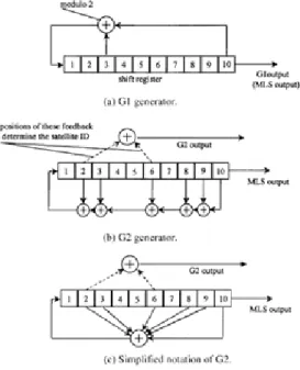
Both G1 and G2 are generated by a maximum-length linear shift register of 10 stages and are driven by a 1.023 MHz clock. Fig. 1 shows the G1 and G2 generators.
Fig. 1a shows the G1 generator and Fig. 1(b) and 2(c) show the G2 generator. Fig. 1(c) is a simplified notation of Fig. 1(b). The basic operating principles of these two generators are similar;
therefore, only G2 will be discussed in detail. A
maximum-length sequence (MLS) generator can be made from a shift register with proper feedback. If the shift register has n bits, the length of the sequence generated is. Both shift generator G1 and G2 have 10 bits, thus, the sequence length is 1,023.
The feedback circuit is accomplished through modulo-2 adders.
The operating rule is modulo-2 adder. When the two inputs are the same the output is 0, otherwise it is 1. The positions of the feedback circuit determine the output pattern of the sequence. The feedback of G1 is from bits 3 and 10 as shown in Fig. 1(a) and the corresponding polynomial can be written as G1:
(1)
The feedback of G2 is from bits 2, 3, 6, 8, 9, 10 as shown in Fig. 1(b) and the corresponding polynomial is G2:
(2)
In general, the output from the last bit of the shift register is the output of the sequence as shown in Fig. 1(a). Let us refer to this output as the MLS output. However, the G2 generator does not use the MLS output. The output is generated from two bits which are referred to as the code phase selections through another modulo-2 adder as shown in Fig. 1(b) and (c). This G2 output is a delayed version of the MLS output. The delay time is determined by the positions of the two output points selected.
Fig. 2 shows the C/A code generator. Another modulo-2 adder is used to generate the C/A code, which uses the outputs from G1 and G2 as inputs.
The initial values of the two shift registers G1 and G2 are all 1 and they must be loaded in the registers first. The satellite identification is determined by the two output positions of the G2
generator. There are 37 unique output positions.
Among these 37 outputs, 32 are utilized for the C/A codes of 32 satellites, but only 24 satellites are in orbit. The other 5 outputs are reserved for other applications such as ground transmission [1].
Fig. 1 G1, G2 maximum-length sequence generators.
Fig. 2 C/A code generator.
Because of C/A code of code length shorter, easy to catch and by capturing C/A code information received, but also can easily capture P code, therefore, usually called C/A code for the
capture code. In GPS navigation and positioning, in order to capture C/A code to determine the satellite signal propagation time delay, usually on the C/A code by the search, and C/A code a total of only 1023 codes element for every 50 bits if second speed search, only 20.5 s to complete.
C/A code has chip of a larger width. If the two chip sequences related to error code element width of 1/10~1/100, then at this time the corresponding ranging error is up to 29.3~2.9 m. Because of its low accuracy, C/A code for the rough captures code.
One of the most important properties of the C/
A code is their correlation result. High autocorrelation peak and low cross-correlation peaks can provide a wide dynamic range for signal acquisition. In order to detect a weak signal in the presence of strong signals, the autocorrelation peak of the weak signal must be stronger than the cross-correlation peaks from the strong signals. If the codes are orthogonal, the cross correlations will be zero. However, the gold codes are not orthogonal but near orthogonal, implying that the cross correlations are not zero but have small values [1].
An operational GPS satellite will transmit an intentionally "incorrect" version of the C/A code where needed to protect the users from receiving and utilizing an anomalous navigation signal. This
"incorrect" code is termed the non-standard C/A (NSC) code. A satellite will transition to NSC as a result of an autonomously detected malfunction in the satellite's navigation payload. Since the NSC is designed to protect the user, it is not for utilization by the user. Block I satellites do not have NSC capability[5].
2.3 P code generated code refined principle P code is bi-phase modulated at 10.23 MHz;
therefore, the main lobe of the spectrum is 20.46 MHz wide form null to null.
The chip length is about 97.8 ns (1/10.23 MHz).
The code is generated from two PRN codes with the same chip rate. One PRN sequence has 15,345,000 chips, which has a period of is 1.5 second, the other one has 15,345,037 chips, and the difference is 37 chips. The two numbers 15,345,000 and 15,345,037 are relative prime, which means there are no common factors between them.
Therefore, the code length generated by these two codes is 23,017,555.5 seconds, which is slightly longer than 38 weeks. However, the actual length of the P code is 1 week as the code is reset every week. This 38 week long code can be divided into 37 different P codes and each satellite can use a different portion of the code. There are a total of 32 satellite identification numbers although only 24 of them are in the orbit. Five of the P code signals (33~37) are reserved for other uses such as ground transmission. In order to perform acquisition on the signal, the time of the week must be known very accurately. Usually this time is found from the C/A code signal that will be discussed in the next section. The navigation data rate carried by the P code through phase modulation is at a 50 Hz rate [1].
2.4 Key characteristics of GPS data
D code navigation message is the user which of the basic navigation and positioning information, in binary form must be sent to the user. Its main contents are: satellite ephemeris, satellite clock correction parameters, ionosphere delay correction parameters, the satellite's job status information and C/A code conversion to capture P code information, all of the satellite ephemeris and so briefly. D code is a non-zero data stream transmission rate for 50 b/s. For the initial phase of the GPS signal simulation, the only data of the binary code as 50Hz-random code can deal with the need to consider the data code itself to carry the physical meaning of [3].
Ⅲ. GPS SIGNAL SIMULATION AND IMPLEMENTATION
3.1 Signal Generation Algorithm and parameter The simulation of the 1st satellite C/A code generated is such as shown in Fig. 3, by using Matlab. Procedures defined in an array, making the satellite with its G2 delay of one-to-one chip:
G2s=[5;6;7;8;17;18;139;140;141;251;252;254;255;256;2 57;258;469;470;471;472;473;474;509;512;513;514;515;516;
859;860;862].
Two gold code sequences generated set two gold code generator of the feedback tap:
save1=reg(3)*reg(10); % G1 feedback code value save2=reg(2)*reg(3)*reg(6)*reg(8)*reg(9)*reg(10);
% G2 feedback code value
In the shift register array of case-by-bit reg mobile will be end of the value of reg(10) into the G1 (G2), the feedback tap values of the mode 2 output save1, save 2 into the first register reg(1).
G1 computing duplicate code so you can generate 1023 times. G2 Code on this basis should be introduced with the corresponding number of satellite chip delay G2s(s), s for the importation of its satellite. To chip delay time as a cut-off point, will then forward the second half of the data, the first half of data transfer, so get G2 code. Will have a code of G1 and G2 multiplied point by point; reverse, namely, a C/A code.
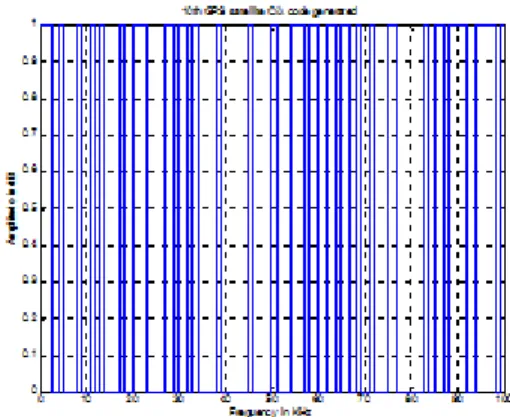
Fig. 3 shows 1st satellite C/A code generated (100 bits), Fig. 4 shows 10th satellite C/A code generated (100 bits).
Fig. 3 1st satellite C/A code generated (100 bits).
Fig. 4 10th satellite C/A code generated (100bits).
Code because the data rate for 50Hz, 0ms long, C/A code rate for 1.023MHz, 1ms long, which is equivalent to a Code D Code tablets contain 20 complete C/A code. Because of C/A code cycle is updated once every 1ms, it captured the general system, only to receive data record 1ms can handle.
1ms at this data, including the D code caused by C/A code phase hopping probability, is very small.
If it caused by the D code phase change, the two adjacent C/A code chip phase difference ± alone, FFT after the correlation peak will be halved, which is the ability to detect out. Then followed the capture system under 1ms data can deal with, because under 1ms data can not contain code from the D-induced C/A code phase hopping [1].
Therefore, in a simulated GPS satellite signal receiver for detecting the time to capture the performance, we cannot consider the impact of D code. In addition, because most receivers are IF receiver, so we can directly enter the a DC Analog.
If satellite signals rather than RF signals. In this way, the whole system will greatly improve operational efficiency. C/A code modulation to the carrier prior to its digital sampling. This involves the selection of the sampling frequency. Usually are used in more Nyquist sampling theorem and band-pass sampling theorem.
3.2 Implementation and results analysis
On the 1st of signal generation by using Matlab:
code1 = digitize (n, , 0,1); % Generate digitalized C/A code
fd1=5.123456789e3; % Set value of the Doppler frequency
lc1 = code1.* exp (j * 2 * pi * ( + fd1) * ts * nn); % multiplied by a frequency modulated carrier wave signal
delay1 = 2831; % Set the C/A code delay value expandlc1 = [lc1 lc1];
1c1 = expandlc1 (delay1: (delay1 + n-1)); % After the delay modulation wave
One of the center frequency is set to 1.25e6Hz, the sampling frequency is set to 5e6Hz, . Fd1 process settings are carrier Doppler frequency search range of ± 10 KHz in any given a value. The data itself does not have any real physical meaning, but follow-up of the simulation platform for more in-depth studies, and math simulation subsystem to calculate the introduction of Doppler carrier-provided interface.
delay1 significance is only a randomly selected sample points less than the purpose of an integer value, which math simulation subsystems calculated the value of PN code delay the introduction of the provision of interfaces. Experiments show delay to
the modulation signal to load up and loaded into the C/A code on the same effect.
In case of the emergence of other satellite signals, each satellite can be set different delay values to form a different PN code delay, setting different values to reflect the different Doppler frequency of the Doppler effect. When signal is superimposed with many stars, the signal is superimposed on the noise. But you can simulate the easy access to the receiver module to capture satellite signals. Single stars signal spectrum is shown in Fig. 5. In case of the 12 stars of the modulation wave superposition, added the rate for 10 of the random noise signal, spectrum of signal is as shown in Fig. 6 [6-8].
Fig. 5 Spectrum of Single-Star signal frequency.
Fig. 6 Spectrum of a multi-satellite signals.
Ⅳ. CONCLUSIONS
GPS satellite C/A code generated a detailed analysis of the principle, and simulation carried out using Matlab, which was a rough simulation of the signal, Matlab simulation of C/A code generation is likely a real satellite signal. Simulation platform permitted to controllable transmission error, such as propagation delay. Doppler effect, multi-path effects, etc., aimed at improving the receiving part of the performance, to enable them to capture the complexity of tracking the satellite signal environment, build better. We can further study the real environment of GPS signals at the satellite signal.
References
[1] J. Tsui, Fundamentals of Global Positioning System Receivers. New York : John Wiley &
Sons, Inc, 2005.
[2] J. Akopian and S. Agaian, “A Fast Position Recovery Approach for GPS Receivers in
Jamming Environments and a
Recommendation for Future GPS Signal Structure,” Military Communications and Innovation(MILCOM), Geneva, Switzerland, Jan., 2005.
[3] E. Kaplan, Understanding GPS: Principles and Applications. Seoul, Korea: Artech House, 1996.
[4] A. El-Rabbany, Introduction to GPS. The Global Positioning System. San Antonio: Artech House, 2002.
[5] GPS Navstar, “Global Positioning System Standard Positioning Service Signal Specification,” 2nd Edition, Technical Repor), GPS Joint Program Office, June 1995.
[6] Y. Suh, “A Comparision of Raptor Code Using LDGM and LDPC Code,” J. of the Korean Institute of Electronic Communication Sciences, vol. 8, no. 1, 2013, pp. 65-70.
[7] S. Chen and H. Suh, “An Effective Decoding Algorithm of LDPC Codes with Lowering Error Floors,” J. of the Korean Institute of Electronic Communication Sciences, vol. 9, no. 10, 2014, pp. 1111-1116.
[8] H. Chen and H. Suh, “An Improved Bellman-Ford Algorithm based on SPFA,” J. of the Korean Institute of Electronic Communication Sciences, vol. 7, no. 4, 2012, pp. 721-726.
저자 소개
장위(Wei Zhang)
1997년 북경연합대학교 졸업(공학사) 2010년 전남대학교 대학원 전자통 신공학과 졸업(공학석사)
현재 북경석유화공학원 교수
※ 관심분야 : 무선통신시스템, 위성통신
서희종(Hee-Jong Suh)
1975년 한국항공대학 항공통신공학 과 졸업(공학사)
1996년 중앙대학교 대학원 전자공 학과 졸업(공학박사)
2006년 ∼현재 전남대학교 전자통신공학과 교수
※ 관심분야 : 네트워크, 그래프이론