Gas flow pattern through a long round tube of a gas fueling system (I)
S. R. IN
Nuclear Fusion Research Lab., Korea Atomic Energy Research Institute, Daejeon 305-353 (Received June 16, 2006)
A gas fueling system composed of a gas reservoir, an on-off valve, and a gas transferring tube, which is the simplest construction for the pre-programmed gas puffing, was simulated by numerically solving the time-dependent one-dimensional gas flow equation. The purpose of the simulation is to establish the relationship between the gas flow pattern (the elapsed time to the maximum flow, the maximum flow rate, the gas pulse duration) and the system parameters (the filling pressure and the volume of the gas reservoir, and the length and the diameter of the gas transferring tube).
Keywords : gas fueling, reservoir, delay, pulse duration
Ⅰ. Introduction
In a gas injection system comprising a gas source, a control valve, and a gas transferring tube, a time lag (or delay) between the opening of the valve and the gas flow out of the tube exit occurs. In a fusion experiment device like a tokamak, to maintain the plasma density at a pre-determined level, the gas injection rate should be properly controlled in accordance with a variation of the particle balance governed by several factors such as the ionization in the plasma, the plasma loss, the gas recycling on the wall, the active pumping and so on. The required time constant of the fueling system could be much less than 100 milli seconds to cope with a short plasma relaxation time. The delay time of the gas flow basically depends on the pressure in the tube as well as on the diameter and the length of the tube. The delay of the gas flow can be
explained as the fill-up time of the tube itself [1]. If the gas flow is in the molecular regime, the delay of the flow is physically the transit time of gas molecules interacting with the tube wall and bouncing back from it repeatedly [2,3].
There are various fueling modes depending on the desired gas flow demand in a practical system; fixed gas amount, constant inlet pressure, constant flow rate, programmed flow, and feed-back control. In this paper, a gas fueling system operated in the mode of a fixed gas amount, which is the simplest pre- programmed gas puffing system composed of a gas reservoir, an on-off valve and a gas transferring tube, is simulated. Besides the delay, there are two other parameters for defining the gas flow pattern of a gas puffing system of this type; the maximum flow rate and the gas pulse duration. Because a gas flow is strongly influenced by the pressure in the
transferring tube (length, diameter).
Simulations on the other fueling modes of the constant inlet pressure and the constant flow rate are reported elsewhere [4].
Ⅱ. Numerical simulation
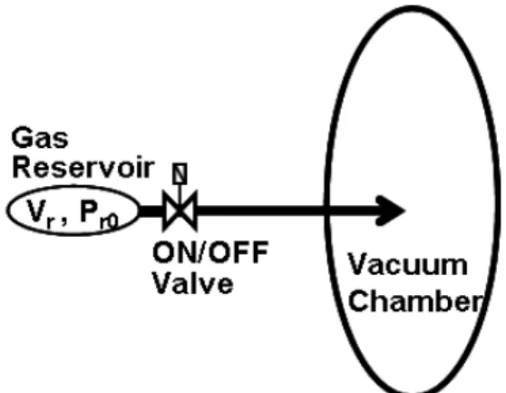
A schematic drawing of the fueling system with a gas reservoir is illustrated in Fig. 1. The tube is considered as an one-dimensional model regardless of the practical plumbing details. The following time-dependent non-linear partial differential equation is established for the gas flow in a tube of a uniform cross-section [3,5].
Fig. 1. Schematic drawing of the fueling system with a gas reservoir.
(1)
where P is the pressure in the tube, Cu is the pressure-dependent conductance of the
×
where Cu1 is the unit viscous conductance, Cu2 is the unit molecular conductance, D [mm]
is the tube diameter, dm [Å] is the diameter of a molecule, M is the molecular mass, Pav
[mbar] is the average pressure in a given segment, and T [K] is the gas temperature.
The gas flow rate at the tube exit is calculated by Eq. (3)
(3)
Eq. (1) indicates that if the pressure distribution in a segment has a negatively convex form (the second derivative is positive), the pressure in the segment continues to increase and vice versa. One of the boundary conditions at the entrance of the tube (x=0), when the volume and the pressure of the reservoir are Vr and Pr, respectively, is given by
≥ (4)
where q(0,t) is the flow rate at the tube inlet. Another one is given by P(0,t)=Pr(t).
The boundary condition at the tube exit (x=L) is simply expressed as P(L,t)=Pch(t),
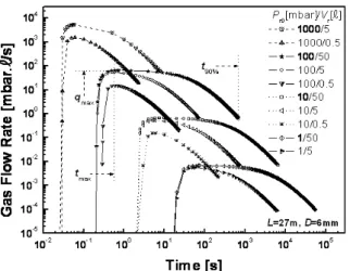
Fig. 2. Variations of the gas flow rate for sev- eral sets of the filling pressure and the volume of the gas reservoir.
Fig. 3. Temporal evolution of the pressure pro- file in a tube (D=6 mm, L=27 m).
where Pch is the chamber pressure. The initial conditions are given as Pr(0)=Pr0, and P(x,0)=
Pch(0)=Pch0. By solving Eq. (1) numerically with the boundary conditions and given values of Cu
and A, the dependence of the gas flow pattern on the tube dimensions and the gas reservoir parameters will be obtained.
In the calculations the volume of the gas reservoir is changed from 0.5 ℓ to 50 ℓ in three steps, and the filling pressure of the hydrogen gas (M=2, dm=2.74) from 0.1 mbar to 1000 mbar in five steps. Although Pch varies with the gas flow rate and the external pumping speed, if Pch is less than 0.001 mbar, Pch can be safely set at zero.
Ⅲ. Results and discussions
The delay of the gas flow in the simulation is defined as the time (tmax) when the gas flow rate at the exit reaches its maximum (qmax).
The time (t90%) when the total accumulated gas flow becomes 90% of the initial gas amount (Pr0Vr) of the reservoir can be considered as the duration of a gas pulse. tmax is roughly expressed as Vp/Cp, where Vp (~D2L) is the inside volume of the tube, and Cp (~DnL-1Pr0m,
{n,m} is {4,1} for a viscous flow, and {3,0} for a molecular flow [3]) is the conductance of a tube of length L. Therefore, the relation tmax~D2-nL2Pr0-m is obtained. qmax is approximately expressed as qmax~CpPr0~ DnL-1Pr01+m, and t90%
can be estimated by t90%~Qr(=Pr0Vr)/qmax~Vr/ Cp~ D-nLPr0-mVr.
Fig. 2 shows the temporal variations of the gas flow rate at the exit of a tube for several sets of the filling pressure and the volume of the gas reservoir. For each condition, the gas flow rate increases abruptly after a certain time lag. In the figure the definitions of the notations tmax, qmax, and t90% are depicted on a curve. All the curves are clearly divided into 4 groups each of which has nearly the same peak height (maximum flow rate) and location (delay) depending mainly on the filling pressure of the reservoir. On the other hand, the pulse duration is determined by both the pressure and the volume of the reservoir. A higher filling pressure generates a shorter delay and a higher peak, and a larger volume apparently leads to a longer pulse. This result indicates that the pulse height and the pulse width can be adjusted separately by controlling the filling pressure and/or the volume of the
(a) (b)
(c) (d)
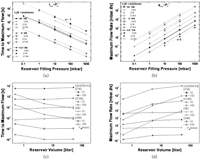
Fig. 4. Dependence of a) the delay time and b) the maximum flow rate on the filling pressure.
Dependence of c) the delay time and d) the maximum flow rate on the volume of the gas reservoir.
gas reservoir.
An example of the temporal evolution of the pressure profile in a tube from t=0 to t=t90% is presented in Fig. 3. In order that the flow rate has a positive value in a tube, the pressure profile must have a monotonic negative gradient. However, the pressure profile is not necessarily linear. The profile for a moment after t=0 is fully concave in the upward direction (pressure is increasing), but from the front part, it gradually becomes convex (pressure is decreasing) up to the time t=tmax. In the transient period between the full concave (at t=0) and the full convex (at t=tmax) profiles, the pressure distribution curve has an
inflection point moving from the entrance to the exit of the tube. After the time t=tmax, the pressure profile does not change in its general shape except in the height.
Fig. 4 shows the dependence of the delay time (tmax) and the maximum flow rate (qmax) on the pressure and the volume of the gas reservoir for 4 different sets of tube dimensions. In Fig. 4a the delay of the gas pulse is a decreasing function of the filling pressure for a fixed volume. The gradients of the lines in the log-log graph are all nearly -1 except at the pressure of 0.1 mbar where the flow is deviated from the full viscous regime. Fig. 4b indicates a well-known
(a) (b)
(c) (d)
Fig. 5. Dependence of the delay time on the tube length for the tube diameters of a) 6 mm and b) 48 mm. Dependence of the maximum flow rate on the tube length for the tube diameters of c) 6 mm and d) 48 mm.
pressure dependence of qmax~P2. It is not too say that tmax and qmax do not depend directly on the volume from all the senses. However, Figs. 4c and 4d indicate considerable variations of tmax and qmax with a volume change (tmax~Vr-n, n≲1, qmax~Vrm, m≲2) especially for long and thick tubes, which originates from a shortage of the supplied gas to completely fill up the interior of the tube when the gas reservoir is too small. A smaller volume results in a longer delay and a lower peak. The increase of the delay, more strictly speaking, is based on the fact that the deficient gas supply causes the working pressure inside the tube and, consequently, the conductance to be
much lower.
The relationship of tmax and qmax to the tube length is plotted in Fig. 5. The delay time is nearly proportional to the square of the tube length for a relatively thin tube with any set of the reservoir pressures and the volumes.
However, in Fig. 5b some lines have gradients of larger than 2 for a thicker tube and a smaller reservoir volume. The smaller the volume, the steeper the gradient. The reason for such phenomena is the same as that explained in the previous paragraph. In Figs.
5c and 5d, qmax typically depends on the tube length with a gradient of -1 in the log-log graph. For a thicker tube and a smaller gas
(a) (b)
Fig. 7. Dependence of the gas pulse duration on a) the filling pressure and b) the volume of the gas reservoir.
(a) (b)
Fig. 8. Dependence of the gas pulse duration on the tube length for the tube diameters of a) 6 mm and b) 48 mm.
Fig. 6. Dependence of the delay time and the max- imum flow rate on the tube diameter at the filling pressure of 10 mbar.
Fig. 7 shows the relationship between the duration of the gas pulse (t90%) and the gas reservoir parameters. t90% is inversely proportional to the filling pressure for a fixed volume as long as the volume is not too small, and the tube is neither too thick, nor too long. t90% is, in
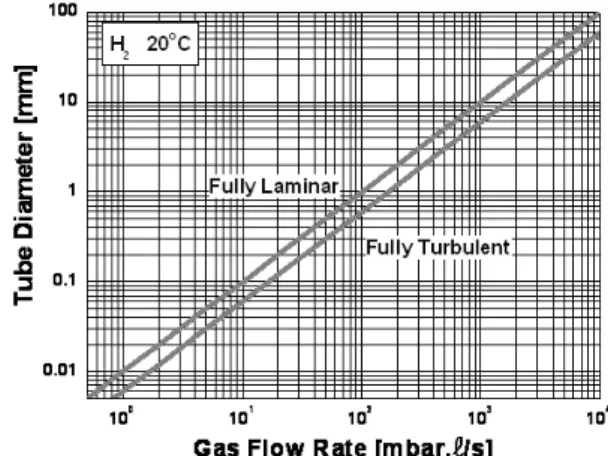
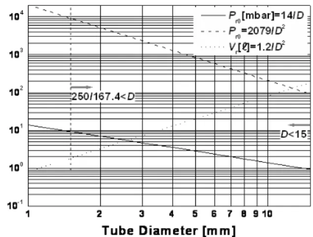
Fig. 9. Dependence of the gas pulse duration on
the tube diameter. Fig. 10. Flow regime as a function of the gas flow rate and the tube diameter.
principle, proportional to the volume for a fixed pressure, but it has a negative gradient with the volume when the tube is thick and long.
In Fig. 8 the pulse duration is increased in proportion to the tube length for a short and thin tube compared with the reservoir volume.
In the case of a small volume and a thick tube, t90% is increased more steeply with the tube length. In Fig. 9, t90% is generally decreased with the tube diameter as t90%~D-4, however, t90% is easily saturated with the diameter when the volume is relatively small and the tube is long.
All the calculation results can be summarized as follows;
tmax~D-mLnPr0-kVrj, 0≲m≤2, 2≤n≲3, k≤1, 0≤j≲1, qmax~DmL-nPr0kVrj, 0≲m≤4, 1≤n≲3, k≤2, 0≤j≲2, t90%~D-mLnPr0-kVrj, 0≲m≤4, 1≤n≲3, k≤1, -1≲j≤1.
The equal signs are satisfied when the gas flow is in the viscous regime and the gas source is large enough. The opposite limits are from the case of a relatively small gas reservoir compared with the interior volume of a tube.
We should pay attention to the fact that the calculated delay time, in some system conditions, may be shorter than the transit
time of the gas molecules which is calculated by dividing the tube length with the thermal velocity, however, this is logically not true.
The reason why such an irrational result is produced is that a calculation condition could be deviated from the flow regime where Eq.
(2) is satisfied (see next section). The minimum meaningful delay time should be given by the transit time (for example, 5.7 msec in a tube of 10 m long for hydrogen gas at 20℃).
Ⅳ. Application
The process of designing a fueling system of the gas reservoir type should start by evaluating the filling pressure and the volume of the gas reservoir, and the dimensions of the gas transferring tube by using the requirements for the gas puffing pattern such as the delay time, the maximum flow rate, and the pulse duration. Sometimes, the minimum distance between the gas source and the gas injection point may be strictly given by a machine environmental layout. The remaining unknown parameters, in this case, are the filling pressure and the volume of the gas reservoir, and the tube diameter. At times, the tube
As an example, let's determine the relevant parameters of a fueling system with the following requirements; tmax(delay)=0.1 s, qmax
(pulse height)=250 mbar∙ℓ/s, and t90%(pulse duration)=60s. It is reasonable to choose a design concept such that the fueling system will be operated in a viscous laminar flow regime where the parametric relationship is well defined and relatively short time lags are generated. Thus the following expressions are derived;
(5)
where ε, β, and δ are constants that can be determined by using simulation results.
There are four unknowns (D, L, Pr0, Vr), while the number of relations are three.
Moreover, the first two relations are not independent of each other for D and Pr0, therefore, the number of non-trivial relations is only two. Fortunately, we can obtain two additional equations of inequality from the viscous laminar flow condition; Pr0D>14 mbar∙
mm below which the flow is in a molecular regime, and qmax/D<167.4 mbar․ℓ/s/mm above which the flow becomes turbulent (refer to Fig.
10) [2,3].
From the data points {tmax=0.755 s, qmax=6.53 mbar∙ℓ/s, t90%=678 s} on the graphs in Figs.
Fig. 11, where an acceptable range of the system parameters can be found. If 4 mm or 10 mm is chosen as the tube inner diameter from a table of commercially available tube dimensions, for a convenience of the tube works, the filling pressure and the volume of the reservoir are given as {1300 mbar, 13 ℓ} or {208 mbar, 81 ℓ}.
Fig. 11. Graph showing the acceptable range of the design parameters. The condition D<15 mm is optional.
As another example, if L is fixed at a certain value, the relation tmax2
qmax=1.89×
10-4L3=37.24 is obtained from Eq. (54), and we can choose an optimum set of tmax and qmax. For example, when L=10 m, if {100 mbar∙ℓ/s, 0.044 s} can be accepted for tmax and qmax, the filling pressure and the volume are 540 mbar and 12.5 ℓ for D=4 mm, and 86 mbar and 78.7 ℓ for D=10 mm, respectively.
Ⅴ. Conclusions
The operating characteristics of the gas fueling system composed of a gas reservoir, an on-off valve, and a gas transferring tube were simulated by a numerical calculation. All the calculation results indicated that the relation- ships between the gas flow pattern (the elapsed time to the maximum flow, the maximum flow rate, the gas pulse duration) and the system parameters (the filling pressure and the volume of the gas reservoir, and the length and the diameter of the tube) were in principle identical with the analytically expected ones with some exceptions. The exceptions can be summarized as follows;
1) When the reservoir volume is too small, the supplied gas amount is not enough to fill up the tube to the design pressure, and the pressure level in the tube decreases at an early time, which results in a decrease of
the conductance and the gas flow, and an increase of the delay time and the pulse duration.
2) The effect of the reservoir volume occurs easily in a relatively long and thick tube.
References
[1] K. H. Burrell, Fast hydrogen gas injection system for plasma experiments, Rev. Sci.
Instrum. 49, 948 (1978).
[2] J. M. Lafferty, Vacuum Science, John Wiley & Sons, Ch.2 and Ch.10 (1998).
[3] S. H. Be et al., Vacuum Engineering (in Korean), Ch.1 and Ch.8 (2000).
[4] S. R. IN, Gas flow pattern through the long round tube of the gas fueling system (II), J. Kor. Vac. Soc., submitted.
[5] W. M. Rohsenow and H. Y. Choi, Heat, mass and momentum transfer, Prentice- Hall, Ch.15 (1963).
(2006년 6월 16일 받음)
기체저장용기, 단순 개폐밸브 및 기체 공급 관으로 구성된 기체연료 주입계는 가장 간단하게 사전에 기체 도입유형을 정할 수 있다는 장점이 있다. 장치의 동 작특성을 알아보기 위해 기체 흐름에 관한 일차원 동특성 방정식을 세우고 수치 적으로 풀었다. 이 계산의 목적은 저장기체 압력, 저장용기 체적, 공급관의 굵 기, 길이 따위의 기계적 요소들과 최대유량까지의 지연시간, 최대유량 값, 기체 펄스폭 따위의 기체 흐름의 유형을 결정하는 인자들 사이의 관계를 정립하려는 것이다.
주제어 : 연료주입, 기체 저장용기, 지연시간, 펄스 폭
* [전자우편] [email protected]