AJCPP 2008 March 6-8, 2008, Gyeongju, Korea
Development of Electrospray Micro Thruster with Super-Hydrophobic PTFE Surface Nozzle Treated by Ar and Oxygen Ion Beam
Y.J. Lee
1, D.Y. Byun
1, Bui Quang Tran Si
1, S.H. Kim
2, B.H. Park
2, M.J. Yu
3, and. M.Y. Kim
4,
1
Konkuk University Korea, Aerospace Information Engineering
2
Konkuk University Korea, Department of Physics
3
Korea Aerospace Research Institute
4
Chonbuk National University Korea, Division of Aerospace Engineering
E-mail: [email protected]
Keywords: Elcrtospray nozzle, Ion beam treatment
Abstract
In this article, in order to fabricate polymer based electrospray device with super hydrophobic nozzle we use PTFE(polyfluorotetraethylene) plate and PMMA (polymethylmethacrylate).
To obtain the super hydrophobic surface nozzle, PTFE surface is treated by argon and oxygen plasma treatment process.
And evaluate the treated surface, perform measuring contact angle, SEM(Scanning Electron Microscope) and AFM(Atomic Force Microscope).
We compare the performance of the super hydrophobic PTFE surface nozzle with raw PTFE and PMMA surface nozzle.
For the ion beam treated PTFE nozzle, the liquid doesn’t overflow and it keeps initial position and meniscus shape. From these results, we expect in cease of superhydrophobic surface nozzle jetting becomes more stable and repeatable.
Introduction
Electrohydrodynamic spraying, or electrospray, has been a subject of intensive research in recent years; for instance, mass spectrometry
1-3), printing technology
4-6)
, and biological microarrays
7).As a mechanism that allows for the dispersal of very fine liquid droplets, its potential applications are seen as numerous. When a low, constant flow rate of a liquid is passed through a capillary, and the meniscus of the liquid subject to an electric field beyond certain strength, an electric charge is induced on the meniscus, and a combination of electrostatic, hydrostatic, and capillary forces elongate the liquid into a conical form known as a Taylor-cone
8-10).
Depending on the flow rate of the liquid and the electric field applied, these cones emit fine particles in a variety of classified regimes or modes, one of which is known as the “cone-jet” mode. This cone-jet spraying mode, in which a steady jet of charged droplets is emitted from the apex of the Taylor-cone,
allows for spray drops in the sub-micron range
10). This emission of charged droplets is properly termed
“electrospray”
9).
Conventional inkjetting devices based on thermal bubble or piezoelectric pumping, however, have some fundamental limitations including size and density of the nozzle array, and ejection frequency, both primarily due to thermal problems. Mechanical jetting has limits in the density of the nozzle array, while the ejection frequency is limited by physical properties, and jetting reliability limited due to the difficulty of fabrication.
On the other hand, electrohydrodynamic jet printing
4,6)
, or electrostatic field induced jetting device
5), based on the direct manipulation of liquid by an electric field, appears more promising. Using a continuously focused colloid jet, Lee, et al.
6)have introduced the electrohydrodynamic printing of silver nanoparticles as a direct writing technology. Park, et al.
4)have been able to use electrohydrodynamic spraying to print images and electrode structures from gold of line width ~2 m. Such structures may be used in the manufacture of circuitry. Lee, et al.
5)have developed an electrospray nozzle specifically for drop-on-demand inkjet printing. Their design has been able to provide relatively stable and sustainable droplet ejections under a wide variety of applied voltages. They showed successfully the feasibility of the electrostatic force to eject liquid droplet for the application to industry. However their technology should be extended to multi-nozzle device which can be manufactured massively and reproduced with appropriate yield.
Hyrdophobicity of a given surface is known to enhance the stability of a liquid meniscus in contact with that surface, and hence the stability of a cone-jet
11)
. However, even on a hydrophobic surface against which a meniscus has a contact angle of around, a cone-jet is not stable and the meniscus on top of the nozzle may overflow onto the surrounding surface.
We need to produce a jetting nozzle that can eliminate these instabilities during jetting. This objective is most readily achieved by fabricating some sort of
877
AJCPP 2008 March 6-8, 2008, Gyeongju, Korea
protruding nozzle; however, a protruding nozzle is difficult to manufacture.
Thus, we realize that a flat nozzle composed of a super-hydrophobic material (that is, with a static contact angle greater than 150°
12)) is the most advantageous, as the resulting high-contact angle of the liquid meniscus at the nozzle’s opening diminishes potentially hazardous leaks to the nozzle’s surface and thus ensures long term stability and repeatability of the electrospray process.
A known process for creating a super-hydrophobic surface is ion beam treatment
13). The efficacy of the ion beam in modifying the topology and wetting characteristics of polymer surfaces has been established
14). Capps, et al.
15)have reported on the effectiveness of argon and argon-oxygen ion beams on polyfluorotetraethylene (PTFE) in particular.
In this article, in order to fabricate polymer based electrospray device with super hydrophobic nozzle, we use PTFE(polyfluorotetraethylene) plate and PMMA(polymethylmethacrylate).
To obtain the super hydrophobic surface nozzle, PTFE surface is treated by argon and oxygen plasma treatment process. And evaluate the treated surface, perform measuring contact angle, SEM(Scanning Electron Microscope) and AFM(Atomic Force Microscope).
And we compare the performance of the super hydrophobic PTFE surface nozzle with raw PTFE and PMMA surface nozzle.
Experimental method
1. Ion beam treatment and contact angle measurement
PTFE (Polytetrafluoroethylene) is chosen as a polymer material for a nozzle because it is well treated by Ar and oxygen ion plasma. This polymer based is fabricated by computer numerical control (CNC) processing technology. PTFE thickness is 3mm; width is 15mm and length is15mm.
In order to obtain the super-hydrophobic PTFE surface, the conditions of modification were examined varying Ar and oxygen concentration and energy levels. The former case is treated in the condition of Ar 2 sccm, oxygen 2 sccm, and 1.0 keV(case 1), and the latter case is in Ar 2 sccm, oxygen 2 sccm, and 1.5 keV(case 2). And observe the time effect, expose time form 20sec to 10min at each condition.
Fig1. is the schematic of Ion beam treatment equipment.
Fig1. The schematic of Ion beam treatment equipment.
Contact angles of 2μl DI water droplet is measured on the treated surface using CCD camera and X-Y stage to investigate the effects of exposure time and energy level. Also degradation characteristics are observed during longer than 2 months.
2. Ion beam treated electro-spray surface nozzle Fig2. shows the schematic of super-hydrophobic PTFE surface nozzle treated by Ion beam. High voltage connected between the pole type electrode inside 700um nozzle and Al ground electrode. The gap between the pole type electrode and ground electrode is 3mm.
Using syringe pump delivered mixed colloid solution. For colloid solution, mixed D.I water 50%, methanol (CH3OH) 49%, and acetone (CH3COCH3) 1%.
When high voltage supply, meniscus shape is changed Taylor-cone and tiny jet spread from the apex of the cone shape meniscus on the ion beam treated surface nozzle.
Fig2. The schematic of Ion beam treated surface PTFE nozzle.
Experiment results
1. Contact angle result of Ion beam treated PTFE surface
In Fig3, Using CCD camera, we observe 2ul droplet contact angle on ion beam treated surface and measure contact angle data. As increasing expose time the super hydrophobicity is increase and contact angle is increase also.
878
AJCPP 2008 March 6-8, 2008, Gyeongju, Korea
Fig3. Contact angle dependence on Ion beam treated time
Fig 3 shows the quantitative data of contact angles are presented showing that the saturated superhydrophobic characteristics can be obtained at optimal conditions of the concentration, energy level, and exposure time.
Fig4. Contact angle results. (Case 1)
Fig5. Contact angle results. (Case 2)
Fig 4 and 5 is observation of degradation characteristics, those are observed during longer than 2 months at atmospheric condition.
In case of Ar 2sccm, O2 3sccm and 1keV(case 1), in 8min expose time initial contact angle is 155° and after 1 month contact angle is 130°. And the other case Ar 2sccm, O2 2sccm and 1.5keV(case 2), in 10min expose time initial contact angle is 161° and after 1 month contact angle is 130°.
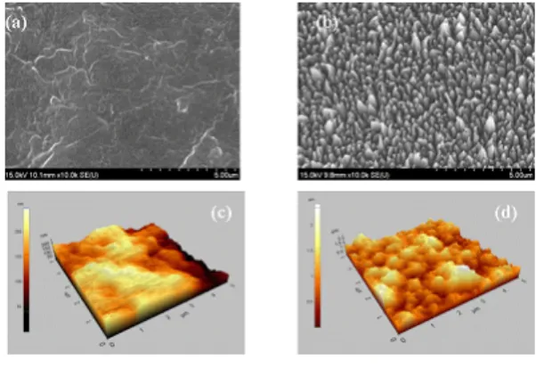
Fig6 shows the morphology of the raw and treated PTFE surfaces.
On the left is the untreated PTFE surface, while on the right is the treated PTFE surface by Ar and oxygen plasma.
The images were taken using an SEM. The raw PTFE surface is quite smooth compared to the treated PTFE surface, which exhibited nanoscale structures due to high energy ion bombardment. To measure the nanostructure quantitatively, we scanned the treated PTFE surface using an AFM(atomic force microscope) as shown in Fig 6.
We see that the width and height of the nanoscale structures are approximately 200nm and 1.2µm, respectively. It is due to these nanoscale structures that we can enhance the liquid meniscus contact angles to super-hydrophobic ranges.
Fig6. SEM and AFM results. (a) and (c) PTFE, (b) and (d) PTFE(Case 2, 10min)
2. Electrospray surface nozzle
The images of electrospray are depicted in fig 7, 8, and 9, respectively, for the PMMA surface nozzle, the non-treated PTFE surface nozzle, and the super hydrophobic PTFE surface nozzle treated by ion beam.
For the PMMA and the PTFE nozzles, the wide spray can be observed on the top of the nozzle, which means the overflow due to low the surface resistance.
Even if successful jetting can be emerged, it is very unstable to get the cone-jet mode. As the operating voltage increases, small and narrow cone-jet is generated.
On the other hand, for the ion beam treated PTFE surface nozzle, the liquid does not overflow and keep the cone shape position even at the low voltage ranges.
And the width of the meniscus at bottom is same as the nozzle diameter, as shown in fig 9.
Because of the super-hydrophobic surface, the liquid can be sustained to form a meniscus with high contact angle.
Fig4. Electro-spray images of tiny droplet on the PMMA surface nozzle. The liquid is used mixed colloid solution. Flow rate 5ul/min, operating voltage
range from 3.3kV to 4.6kV.
879
AJCPP 2008 March 6-8, 2008, Gyeongju, Korea