Vol.21, No.1, (2019), pp.1~5 https://doi.org/10.9714/psac.2019.21.1.001
```
1. INTRODUCTION
The tapes made of HTS-2G have bright perspectives for creating of the magnetic systems in broad range of areas such as medicine (MRI – tomography), magnetic separation, power industry, magnetic cooling et al. It is obvious that the economic appeal of superconducting magnetic systems depends on the cost of magnetic field generation and maintenance. The most economic superconducting systems are working in the “persistent current” mode, i.e. without power supply. The similar mode is reached in melt grown HTS rings [1, 2] or in ring-shape 2G HTS magnet (made of tape with slits) [3].
Wires of low-temperature superconductors, such as NbTi [4] or MgB2 [5] can be connected with very small (<10-15 Ohms) contact resistance. It finally led to their broad application in highly stable magnetic systems, such as MRI tomography. In a number of technical devices, for example, magnetic cooling, separation or power industry, the stability requirements of the field are not so high, and small drift of field can be compensated by a periodic re-magnetization. Re-magnetization procedure was applied to compensate the decrease of the remanent magnetic flux due to relaxation effects in the monodomain rings [2].
At the present time the superconducting solenoids made of HTS tapes with field up to 3 T are constructed [6]. They have inductance 0.2-0.4 H. If in such solenoid one can provide the contact resistance RС < 10-8 Ohm the characteristic damping time will be L/RС 3·107 s or approximately 1 year. Using pulsed re-magnetization of
such system once a week it is possible to provide the stability of the field better than 1%. Thus, the creation of low-resistance joints, and a repeating pulsed magnetization of magnetic systems are relevant tasks.
Magnetization of the short-circuited superconducting system is carried out in two ways, depending on its inductance. For the systems with high inductance the external power source and the superconducting switch is applied [4]. For systems with a low inductance, the pulsed method is promising as it demands less energy during re-magnetization [7-9].
Pulsed field magnetization (PFM) of tablets and rings from melt grown HTSC is widely investigated. At the pulsed field magnetization of the melt-grown ring there can be a local heating of the narrow sector of a ring, and the break of the shielding current occurs [8]. As a result of it the external field easily penetrates into annuli bore. If the pulse duration is shorter than characteristic time of cooling of the superheated area, that magnetic flux "leaves the hole of the ring", and the trapped flux is very small. Moreover, the field can have the opposite direction due to the residual magnetization of a "cold" part of a ring [8]. In the case when duration of falling part of the magnetizing pulse exceeds time of cooling of the channel, then the maximum flux is trapped, as in case of FC process is realized [9].
PFM of the short-circuited multi-turn coil (or the solenoid) essentially differs from the PFM of the ring (or a hollow cylinder). When the magnetic field increases outside of a bulk ring, the shielding current gradually fills the superconductor cross-section from external area to internal. According to the critical state model [(Chapter 7 in [10])], in the penetrated area the density of shielding
Pulsed field magnetization of multi-turn short-circuited stabilized double pancake HTS coil
V. S. Korotkov*,a, E.P. Krasnoperova,c, P. A. Brazhnika, A.A. Kartamysheva, A.M.Bishaevb, and M.V.Kozinstevab
a National Research Center “Kurchatov Institute”, Moscow, Russia
b Russian Technological University(MIREA), Moscow, Russia
c Moscow University of Physics and Technology, Dolgoprugniy, Russia
(Received 18 February 2019; revised or reviewed 25 March 2019; accepted 26 March 2019)
Abstract
The pulsed field magnetization of the short-circuited soldered double pancake coil made of stabilized commercial high-Tc superconductor (HTS) tape is experimentally studied. The evolution of the shielding current induced by the pulsed field and the trapped field after the pulsed magnetization was measured at 77 K. It is shown that the trapped field in the coil is close to the value reached in the field cooling process and reduces weakly at 5-fold increasing of pulsed field amplitude. The current relaxation at t~2 ms after the pulse is defined by the current sharing between the tape's copper coating and the YBa2Cu3O7-d layer. In the intermediate time scale (1 s < t < 100 s) the flux creep in HTS layer dominates. At t > 100 s the current’s relaxation is defined by the resistance of soldered joint between tapes.
Keywords: High-temperature superconductivity, pulsed field magnetization, trapped field magnets
* Corresponding author: [email protected]
current is equal to the critical current density, and equals to zero in the rest area, where there is no field. In the multi-turn coil the shielding current is the same in all its turns, and current density is uniform in the coil cross section. As a result, the resistive state appears when the shielding current reaches critical value for this magnetic field [2].
The possibilities of low-resistance joints creation of tapes from HTS-2G are actively investigated [11] as it allows constructing of autonomous systems. In the work [12] the multi-turn coils from tapes of [13] are manufactured and their isothermal magnetization was studied [12, 14]. Since the PFM process proved to be energy effective for autonomous magnets made of tape stacks and melt-grown HTS. It is significantly important to examine applicability of PFM to the magnetization of short-circuited coils. For the best of our knowledge by the present time there were no systematic researches of the rapid magnetic flux motion in the multi-turn short-circuited solenoids. In this paper the PFM of the short-circuited double-pancake coil made of commercial HTSC-2G tape with stabilization coating in liquid nitrogen is experimentally studied. Induced current relaxation after the magnetization is researched. The rise of the coil temperature during magnetization process is discussed.
2. EXPERIMENTAL SETUP
For the experiment we used a double pancake coil. It had 20 turns wound by the commercial YBCO insulated tape of 4 mm width (manufactured by Super Power Inc.). The pancake coil was manufactured from two pieces of tape and has two lap joints. The lap joints of the coil was produced by Pb-Sn solder [12]. The internal diameter of coil is 60 mm, the external diameter is 66 mm, and the height of the coil is 9 mm. The tape's architecture consists of superconducting layer YBCO (~ 1 m), and a Hastelloy substrate (50 m) with silver cap layer (1 m) and copper stabilizing coating (25 m on each side). According to the experiments on the short tape provide the value Ic = 110 A in self-field [12].
The scheme of the experimental setup is shown on the left part in figure 1. The pulsed current source consists of the condenser battery C discharged through thyristor (Tr) on the two connected is series copper magnetization coils located on both side of the double pancake HTS coil. The
Fig. 1. The experimental scheme (left) and the equivalent electric circuit of the coil (right).
evolution of the external field can be approximated by the half-sine function H(t)=Hasin(t/τ) where Ha is the pulse amplitude, τ ≈ 6.5 ms – pulse duration. The value of the external field is determined by measurement of the voltage on the resistor R.
The shielding current induced in the coil during pulse magnetization within 10 ms, was measured by the calibrated Rogowsky coil and the oscilloscope. Further evolution of current (after the pulsed magnetization) was determined by the change of the magnetic field in the center of the coil. The magnetic field was measured by the Hall’s sensor connected to the Keihley 6221/2182A DC system.
This system provided measurement of the field with a time interval 0.1 s and resolution of 210-5 T. The cooling is produced by the liquid nitrogen. After each pulse the coil was heated above critical temperature to “erase” the trapped magnetic flux before the next magnetization.
On the right part of the figure 1 the equivalent electric circuit which reflects structure of a multilayered tape [13] is represented. The resistance of the superconductor layer depends on the value of the current in this layer Rs=Rs(I) according to the ordinarily used current-voltage curve for HTS superconductors defined by the “power-law” U(I) = U0(I/Ic)N, N~20 [7]. The value of critical current depends on the magnetic field of the coil and its temperature. The normal layers resistance is defined as Rcu. The Rcu depends on the resistance of the stabilization copper layer, the resistance of the silver cap layer and also the substrate resistance connected in parallel. As the copper layer has high conductivity and also its large thickness it makes the dominant contribution to the tape's conductivity. The measured resistance per unit length of the normal layers was derived from the its extrapolation from T > 92 K to T = 77 K is ~ 0,10 mΩ/cm found to be close to [15], so the total resistance of coil's normal layers is Rcu = 36 mΩ (l = 360 cm). The joint resistance in the circuit is Rc connected in series. The calculated inductance of the coil was about L ~ 38 H. The dotted circle (~) designates emf E = SdH/dt arising in the coil during external pulsed magnetization. For the qualitative description of the HTS tape electrodynamics in the pulsed field the equivalent electric scheme defined by the parallel connection of the normal resistor Rcu and the nonlinear resistor with CVC of superconductor was applied (see fig.1.2). According to this at low value of induced current I<Ic the current flows into superconductor either (at low induced current) at higher value of the induced current I>Ic the part of the total current flows into the normal layers.
The suggested circuit can be applied for the qualitative analysis of the experimental results despite this circuit gives rough approximation of real tape's electrodynamic properties. For more precise circuit characterization the non-linear tape inductance [16] and non-uniformity of critical current along the tape's length should be taken in the consideration.
3. RESULTS AND DISCUSSION
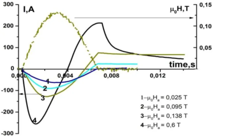
Figure 2 shows the measured evolution of shielding currents in the coil winding (left axis) at different
amplitudes of the magnetizing field. At the low amplitudes (µ0Ha < 0.025 T) the shielding currents is less the critical current, and residual current in the coil is absent. With increasing of Ha the residual current and the trapped field appears. One can see that the value of maximal shielding current rises with the amplitude of the pulsed field. This behavior differs from the magnetization of the melt grown HTS rings and tape stacks where the maximal shielding current is defined by the critical current value and slightly rises with amplitude according to the CVC Imax~(Ha)1/N [17].
The linear dependence on figure 2 (Imax~Ha) may be explained by the assumption that at high pulsed amplitude the most of the current is in the copper covering. For the pulse of 0.138 T (dark yellow line, number 3) the remanent current is close to the value I ~ 70 A and very slightly decreases with time after the end of the pulse. The critical current value for the entire coil is lower than the critical current measured on short tape in the self-field (Ic = 110 A) is explained by the suppression of critical current by the field that produced by the coil.
At the highest amplitude 0.6 T (black line,4) one can notice the fast decrease of shielding current after the pulsed magnetization. It is explained by the damping of the current in copper coating. It is seen that the value of the remanent current after the magnetization with µ0Ha = 0.6 T is lower than at µ0Ha = 0.138 T that can be explained by the rise of temperature of the tape when current goes in the copper layer. The same result could be inferred from the curves in figure 4.
So the figure 2 shows that the existence of the optimal external field amplitude leading to the maximal trapped current is close to 0.138 T. It is difficult to predict the value of this “optimal amplitude” in the case of the multi-turn short-circuited coil as it depends on many factors as inductance L, pulse duration τ, CVC index N, geometry of magnetization coil, resistance of the stabilizing layer Rcu, so this value was found out experimentally. Generally, the I(t) curves in the figure 2 could be qualitatively explained according to the equivalent scheme depicted in figure 1.
Fig. 2. Measured shielding currents in a multi-turn coil (the left axis) at magnetization by amplitudes µ0Ha. From top to down: 0.025 T; 0.095 T; 0.138 T and 0.6 T. A dotted line is an external magnetic field oscillogram with µ0Ha = 0.138 T (the right axis).
After the pulsed magnetization the trapped field decreases over time because of the remanent current relaxation. According to the equivalent scheme (fig. 1), the decrease of the induced current can be described by the well-known equation when the external EMF is equal to zero
L·dI/dt + (R* + Rc)·I = 0 (1)
Here R* is net resistance of Rcu (copper layer) and Rs
(superconducting layer) in parallel connection, and Rc is resistance of soldered joints.
After the pulsed field magnetization of double pancake coil three intervals of time can be distinguished. The first time interval (6.5-8 ms) corresponds to the damping of the induced current in the copper coating. The evolution of the shielding current on this time scale can be seen in figure 2.
The I(t) at this interval can be well approximated with exponential function with damping time cu. By fitting of this interval of experimental data (black curve in figure 2, number 4) one can derive the value of cu = 1.5 ms. The estimation of the characteristic damping time considers that current flows only in the copper covering with Rcu = 36 mOhm then the damping time appears to be very close to the experimental result cu = L/RCu ~ 1 ms.
The intermediate interval of the relaxation curve (1 s < t
< 100 s) which can be seen in figure 3 is defined by the relaxation in the superconducting layer. B(t) in this interval is approximated by the logarithmic function B(t)=B0·(1-S·ln(t/t1)).
In this case the relaxation curve is associated with the nonlinear current voltage characteristic (CVC) of the High-Tc superconducting layer. The CVC of the YBCO as U(I)=U0(I/IC)N, the N~1/S inferred from the B(t) curve on fig. 3 is in the range from 18 to 22 depending on time.
The other way to characterize the relaxation of the remanent current on this time interval (1 s < t < 100 s) is introducing the effective resistance R*(t) of the superconductor, assuming that the relaxation law remains exponential but with varying relaxation time (t) = L/R*(t).
In this interval the resistance of the superconductor is higher than the joint resistance (R*(I)>>Rc). The differential curve in figure 3 gives the dependence R*(t),
Fig. 3. The field relaxation in the multi-turn short-circuited coil after the pulsed field magnetization. External pulse amplitude is 0Ha = 0.138 T.
which is shown in the inset on this figure. It is easy to see that the resistance decreases by at least 2 orders of magnitude and approaches the resistance of the junctions Rc = 24 nΩ.
At the third interval of time (t > 100 s) the resistance of the joint Rc dominates over R*, so the relaxation curve can be described by the exponential law B=B0·exp (-t/c), where c = 1600 s. Long time c characterizes energy dissipation on soldered contacts which general resistance is Rc = L/c ≈ 24 nΩ. Considering that there are two contacts, and the area of soldering of each 4 cm2 it is possible to conclude that the applied technology of soldering [12]
provides joints with resistance per unit area of 48 nOhm·cm2.
The pulsed field magnetization of melt-grown high-Tc
superconductor usually proceeds in the adiabatic conditions as heat exchange time with the thermostat considerably exceeds the pulse duration [7]. In this case the dependence of the trapped field B on the pulsed field amplitude Ha has a narrow maximum [18]. In the range of temperature T = 77 K the trapped field value is approximately the same, as at slow magnetization after cooling (zero field cooling – ZFC). At low temperatures (T
< 40 K), the negative feature of the pulse heating appears.
The decrease of thermal capacity and increase of the pulse amplitude required for the full magnetization cause growth of sample temperature T~10-30 K during the pulse. High
T reduces Btr by 2-3 times in comparison with process of cooling in the magnetic field (FC-process) [19].
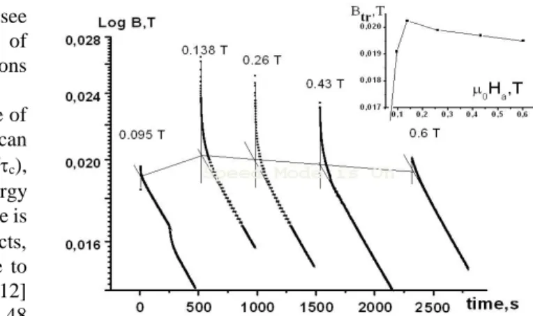
We studied the influence of the magnetizing field amplitude on the value of the trapped field in the center of the coil. In figure 4 evolutions of the trapped fields for various amplitudes of magnetization are presented. The trapped fields (axis Y) are in the logarithmic scale. The parallel lines with an identical inclination, as shown above, characterize a current relaxation on the joint resistance.
Their crossings with vertical lines give initial values of residual superconducting current which provides the trapped field Btr. In an insert in figure 4 the dependence of Btr(Ha) is shown. At small amplitudes (µ0Ha < 0.025 T) the shielding current induced by the pulse in the winding is lower than critical current and it completely shields the external field (Btr = 0). With increasing of Ha the trapped field is observed. Further, the field reaches a maximum at µ0Ha = 0.138 T, and subsequently Btr decreases by 6% with a 5 - fold increase in amplitude.
The maximal trapped field is about Btr = 0.022 T at μ0Ha
= 0.138 T. This value is close to the value obtained by slow cooling in the field [12]. From the measured value of Btr
one can calculate the current in the HTS coil I ~ 58 A. This value is 2 times lower than the critical current measured by the DC (Ic = 110 A) because of lower value of E.
Also it is worth noting that the duration of intermediate region strongly depends on the value of the remanent current induced during the pulse. If the current is higher than critical value, R*> Rc on longer time interval. In case the current is lower than critical one Rc>R* so the exponential current damping on the tape's joint is observed.
Fig. 4. The relaxation of the trapped field at different amplitudes of the magnetizing pulses. From left to right µ0Ha = 0.095; 0.138; 0.23; 0.43 and 0.6 T.
In figure 4 one can notice that for the amplitude of 0.6 T the exponential damping on the joint right after the pulse is realized and flux creep interval is very short. It can be explained by the temperature rise of the superconductor layer during the pulse which causes low value of induced current (I<Ic).
The decrease of Btr at high pulse amplitude is explained by the heating of the superconductor and corresponding decrease of the critical current as Ic=I77(1-/(Tc-77).
Thanks to the dense winding of an insulated coil and a small pulse duration (6.5 ms) the heating can be considered in the adiabatic conditions. The upper bound of the heating temperature can be made in the suggestion that all current flows in the copper coating during the pulse. In this case the generated heat can be calculated from the oscillogram of the shielding current in a tape (Fig. 2) Q = ∫I2·Rcu dt. Then using the volume thermal capacity Cp of tape = 1.8 J/(cm3·K) [14], temperature increase ∆Т and corresponding decrease in critical current is found. Using the I(t) curve from figure 2 for the largest amplitude (µ0Ha
= 0.6 T) the generated heat will increase the coil temperature by 5 K. The decrease of critical current and Btr
will be 40% respectively. In the real situation the induced current flows in the copper layer if the total current higher than Ic. If only a half of the general current flows in copper, then decrease of Btr will be 10% that is close to the observed value. It is difficult to define precisely which part of total current flows into the HTS layer because the value of the critical current of HTS strongly depends on the magnetic field which is changing during the pulse. The equivalent scheme in fig. 1 can be utilized to make more precise energy loss calculation.
All layers of the YBCO are significant in the heat transfer process. In our estimation we consider that time of heat transfer between the composite layers is several orders of magnitude less than pulse duration [20]. Because of this we made a suggestion that the temperature distribution in the tape's cross-section is uniform and for the estimation of temperature rise one must take the total heat capacity of all tape's layers. Low heating of the superconductor at a significant change of the amplitude of the pulsed field is explained by the stabilizing effect of a copper covering.
Higher shielding current occurring in the stabilized coating during the pulsed magnetization leads to that higher amplitude required for the full magnetization. On the other hand the high heat capacity of a copper reduces the temperature rise of the HTS layer.
Similarly, as in the bulk HTS at the high amplitude of the external pulse the heating effect occurs but flux jumps as in [8] was not observed. The absence of “hot spots” supposed to be associated with the transfer of the induced current from the HTS layer to the copper layer bypassing the region of HTS tape inhomogeneities. High value of the thermal conductivity of copper also seems to be responsible for the absence of the localized heating in coil during the pulsed magnetization.
4. CONCLUSION
In the present paper pulsed field magnetization of the short-circuited insulated double pancake multi-turn coil made from the stabilized tape HTSC-2G with two lap joints in liquid nitrogen was researched. From the induced current relaxation after the magnetization the joint resistance per unit of area is turned out to be 48 nOhm·cm2. The dependence of the trapped field on the external field amplitude is qualitatively similar as at the PFM of monodomain discs or tape stacks. Differently from HTS monodomains bulks and HTS tape stacks the amplitude of the field required for the maximal magnetization is 6 times higher than maximal trapped field. This can be attributed to the induced shielding currents in the copper covering during the pulsed magnetization. We suggest that low average heating during the pulsed magnetization of the coil is associated with the transfer of the generated heat and transfer of the induced current among the composite layers.
ACKNOWLEDGMENT
Authors are grateful to A.A. Shikov for measurements of resistance of a tape and to referee for the helpful remarks.
This work was supported by the Ministry of Science and Higher Education of the Russian Federation with agreement No.14.604.21.0197 (the unique identifier of applied scientific research RFMEFI60417X0197).
REFERENCES
[1] M. Tomita, Y. Fukumoto, K. Suzuki, A. Ishihara and M.
Muralidhar, “Development of aa compact, lightweight, mobile permanent magnet system based on high-Tc Gd-123 superconductors,” Journal of Applied Physics, vol. 109, p. 023912, 2011.
[2] V. S. Korotkov, E. P. Krasnoperov and A. A. Kartamyshev,
“Small-sized hybrid magnet with pulsed field magnetization,” J.
Supercond. Nov. Magn., vol. 27, pp. 1845, 2014.
[3] J. Sheng, M. Zhang, Y. Wang, X. Li, J. Patel and W. Yuan, “A new ring-shape high-temperature superconducting trapped-field magnet,” Supercond. Sci. Technol., vol. 30, pp. 094002, 2017.
[4] N. E. Alekseevsky and E. P. Krasnoperov // DAS 197 (1970) 1325 (Russian), and C. J. Kaufman, Rocky Mountain Research Laboratories, Boulder, CO, personal communication, 1992.
[5] J. Ling, J. Voccio, Y. Kim, S. Hahn, J. Bascuñán, D. K. Park, and Y.
Iwasa, “No-Insulation Coil Under Time-Varying Condition:
Magnetic Coupling With External Coil,” IEEE transactions on applied superconductivity, vol. 23, no. 3, 2013.
[6] H. Maeda and Y. Yanagisawa, “Recent Developments in High-Temperature Superconducting Magnet Technology (Review),” IEEE Transactions on applied superconductivity, vol.
24, no. 3, 2014.
[7] M. D. Ainslie, H. Fujishiro, T. Ujiie, et al., “Modelling and comparison of trapped fields in (RE)BCO bulk superconductors for activation using pulsed field magnetization,” Supercond. Sci.
Technol., vol. 27, pp. 065008, 2014.
[8] V. S. Korotkov, E. P. Krasnoperov and A. A. Kartamyshev, “Flux jumps at pulsed field magnetization of monodomain HTS annuli,” J.
Supercond. Nov. Magn., vol. 29, pp. 1893–1896, 2016.
[9] E. P. Krasnoperov, V. S. Korotkov and A. A. Kartamyshev,
“Magnetization of super-conducting rings by long-duration pulses,”
Technical Physics Letters, vol. 43, no. 10, pp. 882–88, 2017.
[10] Martin N. Wilson, “Superconducting Magnets,” Clarendon Press, Oxford, 1983.
[11] K. Ohki, T. Nagaishi, T. Kato et al., “Fabrication, microstructure and persistent current measurement of an intermediate grown superconducting (iGS) joint between REBCO-coated conductors,”
Supercond. Sci. Technol., vol. 30, pp. 115017, 2017.
[12] M. V. Kozintseva, A. M. Bishaev, A. A. Bush, M. B. Gavrikov, K.
E. Kamentsev, N. A. Nizhel’skii, V. V. Savel’ev and A. S.
Sigov, “The properties of short-circuited HTSC coils,” Technical Physics, vol. 87, no. 6, pp. 875–879, 2017.
[13] http://www.superpower-inc.com/
[14] J. Geng, H. Zhang, C. Li, X. Zhang, B. Shen and T. A. Coombs,
“Angular dependence of direct current decay in a closed YBCO double-pancake coil under external AC magnetic field and reduction by magnetic shielding,” Supercond. Sci. Technol., vol. 30, 2017.
[15] J. Pelegrin, E. Martinez, L. A. Angurel, Y. -Y. Xie and V.
Selvamanickam, “Numerical and experimental analysis of normal zone propagation on 2G HTS wires,” IEEE transactions on applied superconductivity, vol. 21, no. 3, 2011.
[16] M. Sjöström, “Equivalent circuit model for superconductors,” IEEE transactions on applied superconductivity, vol. 13, no. 2, 2003.
[17] V. S. Korotkov, E. P. Krasnoperov and A. A. Kartamyshev, “The break of shielding current at pulsed field magnetization of a superconducting annulus (experiment and model simulation),”
Supercond. Sci. Technol., vol. 30, pp. 095004, 2017.
[18] A. A. Kartamyshev, E. P. Krasnoperov, Yu. D. Kuroedov, N. A.
Nizhelskiy and O. L. Poluschenko, “Magnetic relaxation in pulse-magnetized high-temperature superconductors,” Physica C, vol. 469, pp. 805–809, 2009.
[19] Y. Yanagi, Y. Itoh, M. Yoshikawa and T. Oka, “Pulsed field magnetization of a 36 mm diameter single-domain Sm–Ba–Cu–O bulk superconductor at 30, 35 and 77 K,” Supercond. Sci. Technol., vol. 18, pp. 839–849, 2005.
[20] A. G. Page, A. Patel, A. Baskys, S. C. Hopkins, V. Kalitka, A.
Molodyk and B. A. Glowacki, “The effect of stabilizer on the trapped field of stacks of superconducting tape magnetized by a pulsed field,” Superconductor Science and Technology, vol. 26, no.
3, 2015.