제10권, 제4호 (2011년 8월) pp.100~106
차량통신환경에서의 자동이득제어기법 적용
Implementation of Novel Automatic Gain Control in Vehicular Environments†
조 웅* 오 현 서**
(Woong Cho) (Hyun-Seo Oh)
요 약
무선통신환경에서는 RF신호가 매우 심하게 변하는데, 이러한 신호의 변화는 특히 차량통신환경에서 더욱 심해진다.
자동이득제어는 무선통신시스템에서 신뢰성 있는 통신환경을 제공하고 급격하게 변하는 수신신호를 보상하데 중요한 역 할을 한다. 본 논문에서는 수신신호세기값과 아날로그-디지털변환값 두 가지 신호를 이용하는 간단하고 향상된 자동이득 제어기법에 대해 논의한다. 시물레이션과 실제 환경에의 측정을 통해 제안된 기법의 성능을 검증한다.
Abstract
Radio Frequency (RF) signal fluctuates dynamically in wireless communication environments, where this fluctuation is severe especially in vehicular environments. Automatic Gain Control (AGC) is critical in wireless communications to establish reliable communication links and compensate the received signal fluctuation. In this paper, we introduce a simple and novel AGC scheme which uses both Received Signal Strength Indicator (RSSI) and analog-to digital converter (ADC) signals. Performance enhancement of the proposed AGC scheme is verified with practical measurements including simulations.
Key words : Vehicular communications, automatic gain control, receiver, RSSI, ADC
†본 연구는 국토해양부 건설기술혁신사업의 연구비 지원에 의해 수행되었습니다. (스마트하이웨이사업 (07기술혁신A01))
†부산 ITS세계대회 발표논문
* 주저자 및 교신저자 : 한국전자통신연구원 선임연구원
** 공저자 : 한국전자통신연구원 책임연구원
†논문접수일 : 2011년 2월 2일
†논문심사일 : 2011년 4월 19일
†게재확정일 : 2011년 4월 20일
I. Introduction
Intelligent Transportation System (ITS) has been creating new services by combining vehicles and wireless communication technologies. These services can support vehicle safety related applications as well as multimedia applications. These applications can be realized via vehicle-to-vehicle (V2V) communications
and vehicle-to-infrastructure (V2I) communications.
Recently, a standard for V2V and V2I communications has been adopted by IEEE, which is commonly referred as Wireless Access in Vehicular Environments (WAVE) [1]. The WAVE specified the standard for ITS in 5.9 GHz band (5.85~5.925GHz), and ETSI ITS and ISO also follow the most of physical layer/
Medium access control layer (PHY/MAC) structure of
the WAVE. Although the vehicular communications can provide various applications, the most important application is a public safety. To guarantee reliable safety related applications, the following requirements have to be satisfied:
• Latency: Less than 100 msec
• Networking: V2V/V2I
• Communication: Broadcasting, Unicasting
• Mobility: Up to 200km/h
• Communication range: 1km
Among the above requirements, the latency is the most critical factor especially in the safety application.
For short latency, it is necessary to stabilized the received signal rapidly and precisely.
In wireless communications, the input signal of Radio Frequency (RF) at the front end of the communication module varies with wide dynamic range, and this variation becomes severe especially in high mobility. It is reported that the fluctuation of signal is sharp in vehicular environments. Some properties of 5.9GHz signal have been reported in [2- 3]. To compensate the input signal variation and maintain reliable communication links, it is necessary to provide stable signals at the input device of communication module. To satisfy this requirement, it is necessary to implement the automatic gain control (AGC) in communication systems. Several AGC algorithms for wireless local area network (WLAN) and long term evolution (LTE) system are were investigated in [4-7], where all of them use ADC signal for adjusting the received signal. In these systems, the received signal at the input of ADC may cause overflow due to the wide dynamic range which results in clipping of the signal. To compensate this phenomenon, the system requires some additional process, which may delay processing time until the received signal is stabilized. The digital AGC which uses programmable register for storing all necessary information was introduced in [7]. However, this
scheme needs additional time which increases processing time of AGC. Therefore, the existing work may not be suitable in vehicular environments. In this paper, we propose a simple and novel AGC algorithm which is suitable for vehicular environments by using both RSSI and ADC signals, where the former and the later is used for coarse gain control and fine gain control, respectively. The performance of proposed algorithm is verified with simulations and practical measurements.
First, we describe the proposed AGC algorithm including review of OFDM packet structure. Then, simulation and measurement results are presented.
Finally, concluding remarks are given.
II. AGC Algorithm
In this section we briefly review the packet structure of OFDM signal, and then introduce AGC algorithm.
1. OFDM Packet Structure
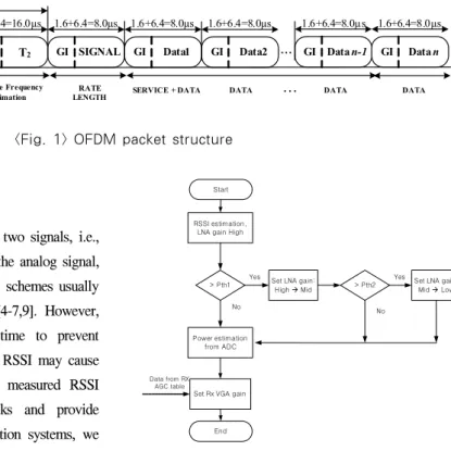
We build an OFDM based communication system with 10 MHz signal bandwidth which is mandatory signal format in the IEEE standard for WAVE.. Notice that all time parameters are doubled to adapt high mobility compared with 20MHz OFDM signal in IEEE 802.11a. Based on practical measurements, it is reported that 10MHz OFDM signal is suitable for vehicular environments [3]. Fig. 1 represents the packet structure of an OFDM signal [8]. The OFDM signal contains preamble, signal field and data field. The preamble consists of short training and long training sequences. The short training sequence has 10 repetitive symbol patterns, and these symbol patterns are used for signal detection, AGC, frequency offset estimation and time synchronization. Since there is limited time in short training sequences, signal detection and AGC operation should be stabilized in fast and accurately.
LNA
LPF
Rx VGA RSSI
ADC LNA/VGA gain contol
LNA Controller Gain(VGA)
Controller
OSC
AGC control unit Antenna
<Fig. 2> AGC block diagram
t1t2t3t4 t5t6t7t8t9t10GI2 T1 T2 GI SIGNAL GI Data1 GI Data2
Signal Detect.
AGC. Diversity Selection
Coarse Freq.
Offset Estimation Timing Synchronization
Channel and Fine Frequency
Offset Estimation RATE
LENGTH SERVICE + DATA DATA
... GI Data n-1
... DATA
GI Data n
DATA
1.6+6.4=8.0µs 1.6+6.4=8.0µs 1.6+6.4=8.0µs 1.6+6.4=8.0µs 1.6+6.4=8.0µs 10 x 1.6=16µs 2 x 1.6 + 2 x 6.4=16.0µs
16 + 16=32µs
<Fig. 1> OFDM packet structure
RSSI estimation, LNA gain High
> Pth1 > Pth2
Power estimation from ADC
Set Rx VGA gain
Yes Yes Set LNA gain :
Mid Æ Low
Data from RX AGC table
Set LNA gain:
High Æ Mid
No No
Start
End
<Fig. 3> Proposed AGC algorithm
2. Proposed AGC algorithm
To guarantee stable AGC operating, two signals, i.e., RSSI and ADC signal which samples the analog signal, are used for gain control. Conventional schemes usually use only one signal to control gain [4-7,9]. However, the ADC requires long processing time to prevent overflow at the RF front end, and the RSSI may cause resolution problem depending on the measured RSSI range. To overcome these drawbacks and provide constant signal strength to communication systems, we design a two-step AGC algorithm using the two control signals. Fig. 2 depicts the overall AGC block diagram, where the AGC operation is carried out using short training symbols of the OFDM preamble signal. The AGC control unit adjusts the gain of two devices, i.e., Low Noise Amplifier (LNA) and receiver variable gain amplifier (Rx VGA). The RSSI and ADC signals control the gain of LNA and Rx VGA, respectively.
LNA is used for adjusting coarse gain by setting three different levels of gain such as High, Medium, and Low. Whereas, Rx VGA is used for fine gain tuning by assigning detailed gain levels. These levels depend on the predefined target signal strength. Based on two control signals and devices, two steps of gain control
are performed.
Fig. 3 represents the proposed AGC algorithm. The AGC algorithm operates as follows:
• Initial setup: Set LNA gain as High.
• Step 1: Coarse gain setting. The RSSI signal is first delivered to the AGC control unit. Then, using threshold 1, the strength of received signal is compared. If the received signal is higher than the threshold 1, set the LNA gain as Medium.
Otherwise, leave the LNA gain as High. If the LNA gain is Medium, the received signal is compared again using threshold 2 which has smaller value than the threshold 1. If the received signal is higher than the threshold 2, set the LNA gain as Low. Otherwise, leave the LNA gain as Medium.
• Step 2: Fine gain setting. Given the LNA gain, the VGA gain is set. When the ADC signal arrives at the AGC control unit, its received signal
<Fig. 6> AGC operation when the strength of input signal is -76dBm.
<Fig. 4> AGC operation when the strength of input signal is -26dBm.
<Fig. 5> AGC operation when the strength of input signal is -46dBm.
strength is estimated. Then, the estimated strength is compared with the predefined target signal strength. After calculating the difference between the received signal strength and target signal strength, the VGA gain is set.
The threshold values (threshold 1 and threshold 2), LNA gain (High, Medium and Low), and target signal strength can be determined by the system design. Using the above algorithm, more stable and reliable AGC operation is established compared with conventional schemes, which maintains reliable communication links.
III. Simulations and Measurements
To verify the performance of the proposed AGC algorithm, we carried out simulations and practical measurements using FPGA based communication module which is compatible with IEEE 802.11p [1].
1. Simulations
In simulations, the AGC operation and settling time are tested by transmitting signals to the communication system which is equipped with the proposed AGC. The transmit signal is generated by signal generator with various signal levels. Then, using the communication module, the AGC setting time and signal detection are tested with the corresponding signal levels, i.e., from -20dBm to -85dBm. Simulation results indicate that signal is detected without any errors, and the average and maximum settling time of the proposed system is approximately 4 μsec and 6 μsec, respectively, which corresponds to 3 and 4 short training symbols of preamble. Table 1 compares the performance of the proposed scheme with the conventional scheme in [5].
It is shown that the proposed scheme provides short settling time by supporting high mobility. Figs. 4, 5 and 6 represent simulation results. Using binary phase shift keying (BPSK) signal with 5.85 GHz center
frequency, RF front end signals of -26dBm, -46dBm and -76dBm are applied in Figs. 4, 5 and 6,
vehicle speed/
relative speed 512bytes 1024bytes 1518bytes 30/60 km/h 2.8ms 4.7ms 6.7ms 60/120 km/h 2.8ms 4.8ms 6.8ms 90/180 km/h 3.3ms 5.1ms 7.5ms 120/240 km/h 3.0ms 5.4ms 7.3ms
<Table 2> Latency for V2V communication
vehicle speed 512bytes 1024bytes 1518bytes
60 km/h 3.1ms 5.2ms 7.4ms
100 km/h 2.9ms 5.1ms 7.1ms
120 km/h 3.0ms 5.3ms 7.6ms
160 km/h 3.2ms 5.3ms 7.5ms
180 km/h 2.9ms 5.1ms 7.0ms
<Table 3> Latency for V2I communication Average
settling time
Maximum
settling time mobile speed Proposed scheme 4 μsec 6 μsec 240km/h
Conventional
scheme [5] 6 μsec 12 μsec 60km/h
<Table 1> Performance comparison
respectively. The upper curve and the lower curve represent the input signal of Modem and signal detection, respectively. In Figs. 4 and 5, big signal parts of the fluctuating curve are the AGC operating period. Although the preamble part and signal parts are indistinguishable in Fig. 6, these two Figs. show that the received signal is settled without any errors.
Notice that a short settling time provides more flexibility to estimate frequency offset and symbol timing, which enhances the overall system performance by providing more margins for stabilization.
2. Practical Measurements
To verify feasibility of the proposed algorithm, we measure the communication range and link setup time using both V2V and V2I communications. With 23dBm EIRP (Equivalent Isotropically Radiated Power)
transmission power, we first tested the communication range, and it is measured that the maximum communication range is approximately 1.5km which corresponds -85dBm of receiver sensitivity. The measurement is carried out highway environments with two vehicles and one infrastructure, where each vehicle and infrastructure are equipped with the communication module.
1) Measurement Setup
For proving the AGC is working properly, we measure the latency. The Latency is measured as follows for both V2V and V2I communications. For V2V case, both vehicles are moving to incoming direction. For V2I case, only vehicle is moving :
• One vehicle (vehicle 1) and another vehicle (vehicle 2)/infrastructure are located at the out of communication range.
• Vehicle 1 moves toward another vehicle (vehicle 2)/infrastructure.
• When vehicle 1 enters the communication range (we use 500m for measurement), vehicle 1 sends a packet to vehicle 2/infrastructure.
• The vehicle 2 or infrastructure returns the acknowledgement signal when the packet is received from vehicle 1.
• When the vehicle 1 receives the acknowledgement signal, the time difference between the vehicle 1's sending time and receiving time is recorded.
The latency is measured with various packet lengths (512, 1024 and 1518 bytes) and various speeds, i.e., 30km/h, 60km/h, 90km/h, 120km/h, 160km/h, and 180km/h. It is worthy pointing out that the successful latency measurement implies AGC algorithm works properly, since the AGC algorithm is applied two times for receiving operation, i.e., vehicle 2/ infrastructure and vehicle 1. If the packet is not received correctly, the latency is not recorded.
2) Measurement results
Tables 2 and 3 represent the latency for V2V and V2I communications, respectively. The results reveal that no error occurs and there is no big difference between V2V and V2I communications. Notice that latency is not related to the communication schemes and the vehicle speed but the packet length itself. Therefore, long packet requires long transmission time physically compared with short packet, which leads to increment of latency. In V2V case, the average latency is 2.975msec, 5msec, and 7.075msec for 512, 1024 and 1518 bytes, respectively. In V2I case, the average latency is 2.02msec, 5.2msec, and 7.32msec for 512, 1024 and 1518 bytes, respectively. All values satisfy the latency requirement which we mentioned section I.
IV. Conclusions
We proposed a simple and novel AGC algorithm which uses both the RSSI and ADC signals to control the AGC. Simulation results show that the proposed algorithm settles the received signal within a short time. In addition, practical measurements reveal that the proposed algorithm works properly in vehicular communications.
References
[1] IEEE Std 802.11pTM-2010, IEEE standard for
information technology-telecommunications and information exchange between systems-local and metropolitan area networks-specific requirements, Part 11, Amendment 6: Wireless Access in Vehicular Environments, July 2010.
[2] G. Acosta-Marum and M. A. Ingram, “Six time-and frequency-selective empirical channel models for vehicular wireless LANs,” IEEE
Vehicular Technology Magazine, vol. 2, no. 4,
pp.4-11, Dec. 2007.[3] L. Cheng, B. E. Henty, R. Cooper, D. D. Stancil and F. Bai, “A measurement study of time-scaled 802.11a waveforms over the mobile-to-mobile vehicular channel at 5.9GHz,”
IEEE Communications Magazine, vol. 46, no. 5,
pp.84-91, May 2008.[4] Y. S. Lee and Y. O. Park, “BER performance of AGC in high-speed portable internet system,” Proc.
of VTC-Fall, vol. 7, pp.4794-4797, Sep. 2004.
[5] J. H. Jang and H. J. Choi, “A fast automatic gain control scheme for 3GPP LTE TDD system,” Proc.
of VTC-Fall, pp.1-5. Sep. 2010.
[6] D. Percls, A. Burg, S. Haene, N. Felber and W.
Fichtner, “An automatic gain controller for MIMO-OFDM WLAN systems,” Proc. of European
Conference on Circuits and Systems for Communications, pp.246-251,July 2008.
[7] I. Lee, J. Son, E. Choi and S. Lee, “Fast automatic gain control employing two compensation loop for high throughput MIMO-OFDM receivers,”
Proc. of Int. Symposium on circuits and systems,
pp.01-04, May 2006,[8] IEEE Std 802.11 2007, IEEE standard for
information technology-telecommunications and information exchange between systems-local and metropolitan area networks-specific requirements, Part 11, June 2007.
[9] Mileti´c, E., Krsti´c, M., Piz, M. and Methfessel, M., “Digital automatic gain control integrated on WLAN platform,” IProc. of World Academy of
Science, Engineering and Technology 41,
pp.571-575, July 2008.저자소개
조 웅 (Cho, Woong)2008년 2월 ~ 현 재 : 한국전자통신연구원 2007년 12월 : University of Florida 박사
2003년 5월 : University of Southern California 석사 1999년 2월 : 한양대학교 석사
1997년 2월 : 울산대학교 학사
오 현 서 (Oh, Hyun-Seo)
1982년 ~ 현 재 : 한국전자통신연구원 1998년 2월 : 연세대학교 박사 1985년 2월 : 연세대학교 석사 1982년 2월 : 숭실대학교 학사