*정회원, 충북도립대학 반도체전자과
접수일자: 2017년 3월 28일, 수정완료: 2017년 5월 28일 게재확정일자: 2017년 6월 9일
Received: 28 March, 2017 / Revised: 28 May, 2017 / Accepted: 9 June, 2017
*Corresponding Author: [email protected]
Dept. of Semiconductor Electronics, Chungbuk Prov. Univ., Korea https://doi.org/10.7236/JIIBC.2017.17.3.107
JIIBC 2017-3-12
클러스트-트리 무선센서네트워크에서 비콘 프레임 충돌 회피를 위한 멀티채널 시분할 스케줄링
Multi-Channel Time Division Scheduling for Beacon Frame Collision Avoidance in Cluster-tree Wireless Sensor Networks
김동원
*Dongwon Kim
*요 약 클러스트-트리 무선센서네트워크에서 비콘활성화 모드일 때 비콘 충돌은 아주 중요한 문제가 되고 있다. 본 논문에서는 비콘 충돌 현상을 회피하고 네트워크 확장성을 제공하기 위하여 멀티채널 시분할 스케줄링 기법을 제안한 다. 코디네이터는 할당된 채널들과 타임슬롯들에 대한 정보를 포함하고 있는 비콘프레임을 방송하는 역할을 한다. 이를 통해 새로운 노드는 자신의 채널과 타임슬롯을 결정하게된다. 제안 방식의 성능을 전형적인 지그비 방식과 비교한다.
제안 방식은 클러스트 트리 무선센서네트워크상에서 비콘 충돌을 방지하고 네트워크 확장면에서 효과적으로 구성이 가 능하게 한다.
Abstract
In beacon-enabled mode, beacon collision is a significant problem for the scalability of cluster-tree wireless sensor networks. In this paper, multi-channel time division scheduling (MCTS) is proposed to prevent beacon collisions and provide scalability. A coordinator broadcasts a beacon frame, including information on allocated channels and time-slots, and a new node determines its own channel and time-slot. The performance of the proposed method is evaluated by comparing the proposed approach with a typical ZigBee. MCTS prevents beacon collisions in cluster-tree wireless sensor networks. It enables large-scale wireless sensor networks based on a cluster tree to be scalable and effectively constructed.Key Words :
beacon collision, multi-channel, time division scheduling, cluster tree WSNⅠ. Introduction
For a wireless sensor network (WSN) consisting of sensor nodes scattered throughout a relatively wide area, a cluster- tree or mesh structure should be used instead of a star topology structure. In a cluster-tree topology, a cluster head gathers data from sensor nodes
in the cluster. Reducing the power consumption of sensor nodes requires a low duty cycle, which is obtained by introducing an active period and standby period. For a low duty cycle, the cluster-tree WSN should be in a beacon-enabled mode.
In many literatures about WSN
[1][6][7][8][9], there are
many proposals for beacon-enabled MAC schemes to
save power consumption in cluster-tree WSNs (e.g.
S-MAC
[7], Adaptive S-MAC
[8], and EE-MAC
[9], etc).
IEEE 802.15.4 standard
[1], which is adopted as ZigBee specification, is also used to organize cluster-tree topology using beacon-enabled mode. But these protocols do not consider beacon scheduling scheme.
Beacon-enabled mode requires both synchronization and scalability. A cluster-tree network consists of coordinators (also called ZigBee routers). Each coordinator generates periodic beacon frames, which it uses to synchronize the nodes of an adjacent neighbor cluster. When periodic beacon frames are transmitted without a specific schedule, they may collide with each other or with a data frame.
There are three reasons why beacon frames collide.
First, a direct beacon frame collision occurs when at least two coordinators exist in each other’s radio range (direct neighbors or in a parent-to-child relationship) and transmit beacon frames at almost the same time.
Second, an indirect beacon frame collision occurs when at least two coordinators that do not exist in each other’s wireless transmission range transmit beacon frames almost simultaneously in an overlapping radio range. Third, a collision between a data frame and beacon frame occurs when the beacon frame is transmitted during an active period of a neighboring cluster.
In a time division beacon scheduling (TDBS) mechanism
[2], time is divided such that the beacon frames and data frames of a certain cluster are transmitted during an inactive period of neighboring clusters in order to build synchronized cluster-tree WSNs. TDBS is a type of single channel/time division scheduling; however, in this paper, multi-channel time division scheduling (MCTS) is proposed to prevent beacon collisions and provide scalability. Some methods for increasing capacity and reducing power consumption through the use of a multi-channel protocol have been proposed
[3][4][5]; however, most of them are applicable to IEEE 802.11 ad hoc networks.
The proposed MCTS is designed for IEEE
802.15.4/ZigBee cluster-tree networks.The remainder of this paper is organized as follows. In section II, a frame structure and multi-channel time-slot scheduling for the synchronization of clusters are proposed. In section III, a performance evaluation is presented. Finally, in section IV, some concluding remarks and a description of future work are provided.
Ⅱ. Multi-channel Time Division Scheduling
The proposed concept of MCTS is summarized as follows: Clusters using the same channel avoid mutual interference with each other by selecting the scheduling of superframe duration (SD) exclusively. Within the same SD, clusters use different channels. As a result, beacon collision and packet loss can be avoided.
According to IEEE802.15.4/ZigBee standard, the coordinator of each cluster sends the beacon periodically through its own channel. The joined devices to this coordinator are only able to communicate each other during the corresponding SD on the corresponding channel. A coordinator usually plays 2 kinds roles. One is as a child. The other is as a parent. When it plays as a child, it obeys parent’s channel and SD schedule because it joins its parent.
When it plays as a parent, it manages its channel and SD schedule for its children by sending beacon periodically. Accordingly, parent’s SD schedule and child’s SD schedule should not overlap each other.
They should not also overlap with the SD schedules of neighbors. Consequently, for a coordinator to join and configure a PAN which is beacon-enabled cluster-tree structure, it has to know the channel and SD scheduling information of neighbors within 2-hop, and decide its own channel and SD schedule.
So far, the role and function of the coordinator and
the device is defined exactly as in IEEE802.15.4/ZigBee
or MCTS. However, in order to use multi-channel and
schedule SD exclusively in MCTS, the operation of
coordinator is slightly modified and the payload of beacon is used. The added payload contains the information about channel and SD schedule of neighbors, which is represented in bit-vector form.
Each bit corresponds to a specific channel and SD schedule. An available SD schedule is mapped to a time-slot which is a time period divided by beacon order (BO) and superframe order (SO) parameters.
When a node attempts to join a network, it first scans beacons from its adjacent coordinators like IEEE 802.15.4 standard. Using payload information included in a beacon, the joining node selects a channel and time-slot pair among those unused by other nodes (or clusters) within 2-hop. Because the proposed MCTS follows the same procedure for scan/join/association like IEEE802.15.4/ZigBee standard, it is almost similar to IEEE802.15.4/ZigBee standard except having about 10 bytes overhead in beacon payload. Therefore, the protocol complexity of MCTS is the same as the standard. Nevertheless, its performance outperforms IEEE802.15.4/ZigBee standard by using multi-channel and well scheduled SD.
1. Time Division Scheduling of Superframe Duration
When clusters are assumed to use the same beacon order (BO) values and superframe order (SO) values in IEEE 802.15.4 networks, a beacon interval (BI) and a superframe duration (SD) satisfy the following equations:
×
×
The period of a time-slot is defined as same as the superframe duration. If a node uses a channel and a time-slot, it sleeps during other time-slots within the BI. This prevents interference with other nodes. The number of time-slots, m, is BI/SD, which is equal to 2BO-SO. Fig. 1 shows an example diagram of channels(CH#) and time-slots(T#), where eight time-slots per channel are used and (BO, SO) is (6, 3).
Fig. 1. Example of time-slots in eight channels with (BO, SO) = (6, 3).
그림 1. 8채널에서 (BO, SO) = (6, 3) 경우 타임 슬롯 예
2. Beacon Frame and Multi-channel Time-Slot Vector
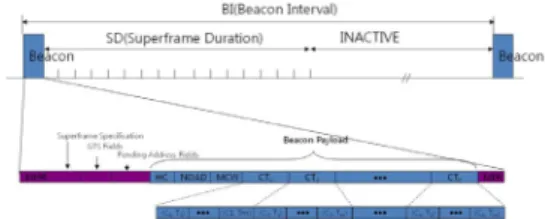
Fig. 2 shows the beacon frame structure used in this paper. The frame structure basically conforms to the IEEE 802.15.4 standard, and the payload field of the beacon frame can be designed according to the purpose of the network.
The HC field in the beacon payload denotes a hop count from a PAN coordinator (PNC). The depth of a tree structure can be obtained from the HC, and thus, a parent-child relationship can be obtained. The number of associated devices (NOAD) field is the number of associated devices used for admission control to ensure load balance and cluster performance.
The my channel and time-slot (MCT) field indicates a channel and time-slot that the node transmitting the beacon uses. It can be recognized by other adjacent nodes by observing a beacon.
Fig. 2. Beacon frame structure.
그림 2. 비콘 프레임 구조
Multi-channel time-slot vectors CT
1through CT
nshow the occupancy of time-slots in a channel when n
channels are used. The element CTk is a bit
representing whether a channel and time-slot pair are occupied. A bit corresponding to an unoccupied channel and time-slot is indicated with 0; otherwise, it is 1.
When CTk is generalized according to the number of channels(1≤k≤n) and the number of time-slots(1≤j≤
m), it is expressed as follows:
CT
k={(C
k,T
1), (C
k,T
2), ..., (C
k,T
j), ..., (C
k,T
m)} , (2)
where (C
k, T
j) is 1 if channel k and time-slot j are occupied, or (C
k, T
j) is 0 if channel k and time-slot j are unoccupied.
Because HC and NOAD are dependent of network scalability, 2 bytes length field is sufficient for a cluster tree structure network. When a network has parameters such as BO=6, SO=3 and 8 channels, k*j is only 64 bits. Therefore MCT field length is 6 bits.
Compared with standard, overhead is about 10 bytes, which is calculated from the sum of HC, NOAD, MCT and k*j.
3. Join Procedure of the MCTS
A PNC communicates with a coordinator, i.e., its child node, by differentiating a channel according to each time-slot in one BI. The coordinator performs operations described in the IEEE 802.15.4 standard, and when the coordinator joins a parent node, the coordinator uses a channel of that parent node. The coordinator joins the parent node in such a way that its time-slot schedule does not collide with the time-slot schedules of the parent node and 2-hop adjacent nodes using a corresponding channel. For this purpose, the time-slot schedule of the coordinator is determined according to the proposed MCTS.
Fig. 3 shows a join procedure of the proposed method. Principles considered when a node joins a network are as follows. First, the node joins a closest PNC. In other words, the node reduces network delay and the HC by joining a PNC having a small HC.
Second, the node joins according to load balance so that the maximum NOAD is not exceeded. Third, even if
the node desires to join as a coordinator, when the node cannot be assigned with a channel and a time-slot, the node joins as a device.
DO Active Scanning.
IF (beacons are received from neighbor coordinators) then DO Choose a coordinator with smallest HC under the condition that NOAD is not exceeded
maximum.This coordinator is determined to be a parent node.
IF (I am a RFD) then
Join the coordinator as a child.
ELSE IF (I am a FFD) then
DO Select a channel and time-slot pair among those unused by other nodes(or cluster)
within 2-hop.
IF (a channel and time-slot pair) then
Join the coordinator as a child and also play a role as new coordinator with the selected channel and time-slot.
ELSE Joining is failure END IF
END IF
ELSE Joining is failure.
END IF
Fig. 3. Join procedure 그림 3. 조인 절차
When a node attempts to join a network, it first obtains network information (a beacon list) from its adjacent coordinators through a scan, such as an energy detection (ED) scan or an active scan described in the IEEE 802.15.4 standard. The node with the smallest HC among the HCs of other observed beacons is selected, and if the NOAD of the node does not exceed the maximum value, that node is determined to be a parent node. Using MCT and CTk information included in a beacon that is periodically emitted from adjacent coordinators, the joining node selects a channel and time-slot pair among those unused by other nodes (or clusters) within 2-hop. After joining the parent node, the node can operate as a coordinator if it is a full function device (FFD). It transmits a beacon for synchronizing devices according to the activating channel and time-slot schedule.
If a new node cannot be assigned to a channel and time-slot, it joins the parent node as a device or becomes an orphan.
If MCTS is used on a single channel without
considering HC and NOAD, it is the same as the
standard. FFD and RFD are also the same as the
standard. It is thought that SD scheduling method is just included in the standard. Because the proposed MCTS follows the same procedure for scan/
join/association like IEEE802.15.4/ZigBee standard, it is almost similar to IEEE802.15.4/ZigBee standard except having about 10 bytes overhead in beacon payload.
Therefore, the protocol complexity of MCTS is the same as the standard. Nevertheless, its performance outperforms IEEE802.15.4/ZigBee standard by using multi-channel and well scheduled SD.
III. CHANNEL AND TIME-SLOT SELECTION ALGORITHM
First, look at an example how to select a time-slot in a single channel when a new node wants to join.
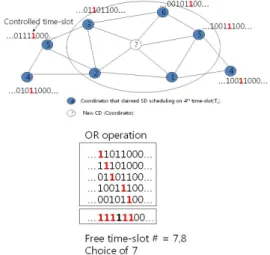
Fig. 4. Time-slot selecting example in a single channel
그림 4. 단일 채널에서 타임슬롯 선택의 예
FIG. 4 is a conceptual diagram illustrating a time-slot selecting algorithm in a single channel.
Referring to FIG. 4, the number of each node is a currently occupied time-slot value. In a binary value expressed in a bit vector (CTk) about a channel and a time-slot, 1s in bold(red-colored) represent time-slots occupied by the corresponding node and other 1s are
time-slots occupied by neighboring coordinators within a wireless transmission range of the corresponding node.
When a new coordinator desires to join the network, its own time-slot may be selected as follows. When an OR operation is performed on CTk of the observed beacons, a time-slot indicated as 1 is a time-slot occupied within 1 or 2 hops. Accordingly, one time-slot may be randomly selected from among time-slots indicated as 0.
As a result, time-slot #7 and #8 are free, and when time-slot #7 is selected, the node may join the network as a coordinator having the schedule of time-slot #7.
For a clear understanding of the proposed method, an example of the multi-channel operation is illustrated in Fig. 5. This figure illustrates the process of constructing a cluster-tree network in multiple channels according to the proposed method. In the example network, there are 3 channels and 6 time-slots that can be assigned to each channel; the maximum NOAD of a PNC is 6, and the maximum NOAD of other nodes is 2. In this figure, the first and second numbers in each circle indicate the channel and time-slot used by the node, respectively, e.g., 1-2 means that the node selects channel 1 and time-slot 2 as MCT. A dotted line indicates a neighboring node, and a solid line indicates that a node is joined a network.
Since the PNC communicates via a channel according to each time, which corresponds to each time-slot, the PNC occupies channel and time-slot pairs, (1-1), (2-2), (3-3), (1-4), (2-5), and (3-6) as its MCT, which is marked with ‘red-colored 1’ in CTk. As shown in Fig. 5-(b), a new node A wants to join the network by having the PNC as a neighboring node.
The NOAD of the PNC does not exceed the maximum
value of 6, and thus, the new node determines the PNC
to be a parent node and selects channel 1 and time-slot
2 as its own MCT. Accordingly, the multi-channel
time-slot vector of the new node A and PNC becomes
{CT1,CT2,CT3}={{1,1,0,1,0,0},{0,1,0,0,1,0},{0,0,1,0,0,1}}.
Another new node B then wants to join the network, as shown in Fig. 5-(c). That node B determines the PNC to be the parent among the neighboring nodes because the HC is smaller and the NOAD does not exceed the maximum value. It selects channel 2 and time-slot 3, which is an unoccupied pair among the channel and time-slot pairs, for its own MCT. The NOAD of the PNC then increases by 1, and thus [HC, NOAD] of the PNC becomes [0, 2]. If the multi-channel time-slot vector of the PNC is {{1,1,0,1,0,0}, {0,1,1,0,1,0}, {0,0,1,0,0,1}}, a multi-channel time-slot vector of the new node B and single-hop neighbor node A changes to {{1,1,0,1,0,0}, {0,1,1,0,1,0}, {0,0,1,0,0,1}} because channel 2 and time-slot 3 are assigned to the new node B.
Another new node C then wants to join the network, as shown in Fig. 5-(d). That node C determines the PNC to be the parent among the neighboring nodes because the HC is smaller and the NOAD does not exceed the maximum value. It selects channel 3 and time-slot 4, which is an unoccupied pair among the channel and time-slot pairs, for its own MCT. The NOAD of the PNC then increases by 1, and thus [HC, NOAD] of the PNC becomes [0, 3]. If the multi-channel time-slot vector of the PNC is {{1,1,0,1,0,0}, {0,1,1,0,1,0}, {0,0,1,1,0,1}}, a multi-channel time-slot vector of the new node C and single-hop neighbor node B changes to {{1,1,0,1,0,0}, {0,1,1,0,1,0}, {0,0,1,1,0,1}} because channel 2 and time-slot 3 are assigned to the new node C.
[0,0]
{{1,0,0,1,0,0}, {0,1,0,0,1,0}, {0,0,1,0,0,1}}
PNC
[1,0] 1-2 {{1,1,0,1,0,0},
{0,1,0,0,1,0}, {0,0,1,0,0,1}}
[0,1]
{{1,1,0,1,0,0}, {0,1,0,0,1,0}, {0,0,1,0,0,1}}
PNC
1-2 2-3 PNC
[0,2]
{{1,1,0,1,0,0}, {0,1,1,0,1,0}, {0,0,1,0,0,1}}
[1,0]
{{1,1,0,1,0,0}, {0,1,1,0,1,0}, {0,0,1,0,0,1}}
[1,0]
{{1,1,0,1,0,0}, {0,1,1,0,1,0}, {0,0,1,0,0,1}}
3-4 [0,3]
{{1,1,0,1,0,0}, {0,1,1,0,1,0}, {0,0,1,1,0,1}}
1-2 2-3 [1,0]
{{1,1,0,1,0,0}, {0,1,1,0,1,0}, {0,0,1,0,0,1}}
[1,0]
{{1,1,0,1,0,0}, {0,1,1,0,1,0}, {0,0,1,1,0,1}}
[1,0]
{{1,1,0,1,0,0}, {0,1,1,0,1,0}, {0,0,1,1,0,1}}
PNC
(a) (b)
(c) (d)
A
A B
A B
C
Fig. 5. Process of constructing a cluster tree network using the proposed mechanism.
그림 5. 제안방식을 사용한 클러스트 트리 네트워크 구축 과정
Subsequent operations are performed in the same manner. In other words, a new node selects a neighboring node that has the smallest HC and whose NOAD does not exceed the maximum value as a parent node. Here, if there is no node whose NOAD does not exceed the maximum value, the new node cannot join the network. The new node selects a time-slot that has yet to be occupied by neighboring nodes. For the new node to communicate with the parent node using the same channel, the new node has to select a time-slot that belongs to the channel used by the parent node.
IV. PERFORMANCE EVALUATION
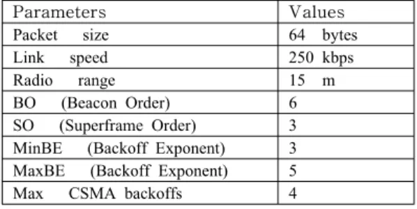
Table 1. Parameters used in the performance evaluation.
표 1. 성능평가에 사용된 파라미터들
Parameters Values
Packet size 64 bytes
Link speed 250 kbps
Radio range 15 m
BO (Beacon Order) 6
SO (Superframe Order) 3 MinBE (Backoff Exponent) 3 MaxBE (Backoff Exponent) 5
Max CSMA backoffs 4
The proposed MCTS for scalable cluster-tree
networks was evaluated through a comparison with the
synchronization of the ZigBee standard, where all
nodes use the same channel. All nodes except the PAN
coordinator increased in their packet generation rate by
0.05 kbps. The performances, shown in the graphs
were measured at the normalized offered loads in the
range of 0 to 0.20. All generated packets should be
delivered to the PAN coordinator, and the nodes are
assumed to have no mobility. The number of channels,
n, is set to 3, and the number of time-slots, m, is set
to 8. Using the parameters listed in Table 1 for the
simulation environments, we conducted a simulation for
the throughput, average transmission delay, beacon
loss ratio, and packet loss probability.
Fig. 6. Normalized throughput.
그림 6. 일반화된 스루풋
Fig. 7. Average latency.
그림 7. 평균 지연시간
Fig. 8. Beacon loss ratio.
그림 8. 비콘 손실 율
Fig. 6 shows that the normalized throughput of the proposed method was higher than that of the ZigBee networks. Using three channels reduced the collision probability in the CSMA-based protocols and ensured higher network throughput than in ZigBee under high offered loads. As shown in the figure, when a normalized offered load was around 0.05, the normalized throughput of ZigBee saturated to 0.05, and the normalized throughput of the proposed method saturated to 0.12. In ZigBee, when BO-SO is 3, the active period is 12.5% of the beacon interval. In the
proposed method, because a node can be active while another node is in an inactive period, the percentage of the active period is more than 12.5%.
Fig. 7 shows the average latency according to the normalized offered load. When the next node is in an inactive period, packets cannot be forwarded until the node returns to an active period. Thus, the latency from the node to the PNC depends on the percentage of the active period. This is the reason the proposed method yields a shorter latency.
Fig. 8 shows the beacon loss ratio caused by interference and collisions. In ZigBee, the number of beacon collisions increases with the offered load.
However, because the proposed method uses a beacon scheduling that considers nodes within two hops, no beacon collisions occur.
V. CONCLUSIONS
This paper proposes a multi-channel time-slot scheduling method for preventing beacon collisions and interference in cluster-tree type IEEE 802.15.4/ZigBee wireless networks. The proposed method is not only used in a single channel but can also be used in 16 channels in a 2.4 GHz band of the IEEE 802.15.4 standard. It includes a channel assigning method for constructing a cluster tree so that clusters do not interfere with each other, and a scheduling method between clusters to prevent beacon collisions. The proposed method enables large-scale wireless sensor networks based on the cluster tree to be scalable and effectively constructed.
References
[1] Wireless Medium Access Control (MAC) and
Physical Layer (PHY) Specifications for
Low-Rate Wireless Personal Area Networks
(WPANs), IEEE Std 802.15.4-2006, Sep. 2006.
[2] A Koubâa et al., “TDBS: a Time Division Beacon Scheduling Mechanism for ZigBee Cluster-Tree Wireless Sensor Networks,” Real-Time Systems, vol. 40, no. 3, Dec. 2008, pp. 321-354.
[3] S. L. Wu et al., “A Multi-Channel MAC Protocol with Power Control for Multi-hop Mobile Ad-hoc Networks,” The Computer Journal, vol. 45, no. 1, 2002, pp. 101-110.
[4] J. H. Chen and S. T. Sheu, “Distributed Multichannel MAC Protocol for IEEE 802.11 ad hoc Wireless LANs,” Computer Communications, vol. 28, no. 9, June 2005, pp. 1000-1013.
[5] T. M. Trung and J. H. Mo, “A Multichannel TDMA MAC Protocol to Reduce End-to-End Delay in Wireless Mesh Networks,” ETRI journal, vol. 32, no. 5, Oct. 2010, pp. 819-822.
[6] I. Demirkol et al., “MAC protocols for wireless sensor networks: a survey,” IEEE Communications Magazine, vol. 44, no. 4, pp.115-121, 2006.
[7] W. Ye et al., “An energy-efficient MAC protocol for wireless sensor networks, ” in Proc. of IEEE INFOCOM 2002, pp. 1567-1576, 2002.
[8] Young-bok Cho, Sang-ho Lee, Sung-HeeWoo, “An Adaptive Clustering Algorithm of Wireless Sensor Networks for Energy Efficiency,” The Journal of The Institute of Internet, Broadcasting and Communication(JIIBC), VOL. 17 NO. 1, February 2017.
[9] D. W. Kim, T. G. Park, “An Energy Efficient MAC Protocol Providing Guaranteed Service for Wireless Sensor Network,” KSII TIIS Vol. 5, Issue 1, 2011.1.31, pp. 123-140
저자 소개 김 동 원(정회원)
∙2016년 제16권 제4호 참조