79
Novel Doppler effects compensation schemes based on constellation estimation of OFDM system
Byung-Seub Lee* Lifelong Member
ABSTRACT
A new and effective Doppler effects compensation scheme for orthogonal frequency division multiplex(OFDM) system based on constellation estimation is presented with analytical descriptions which quantitatively clarify the mechanism of inter-carrier interference(ICI). The proposed compensation techniques, applicable both frequency and time domain with remarkable accuracy, are crucial to the future OFDM system operating on ultra high speed mobile vehicles.l
Key Words : Doppler effects, Inter-Carrier interference(ICI), OFDM
*Korea Aerospace University School of Electronics and Information Engineeering, [email protected] 접수일자 : 2017년 5월 23일, 수정완료일자 : 2017년 5월 29일, 최종게재확정일자 : 2017년 5월 31일
I. Introduction
OFDM has emerged as one of the most practical and potent system for mobile data communication in frequency selective and relatively low time-selective fading channel.
However in near future, OFDM systems are expected to operate on express railroad trains and airplanes which have to be experiencing high level of time selectivity. The OFDM systems operating on the fastest mobile vehicles at high satellite frequency band will experience severe ICI due to Doppler frequency shift (DFS). The vulnerability of OFDM system to the DFS is explained by the existence of saturated bit error floors even in relatively low range of frequency offsets with irrelevancy of random noise [1],[2]. In an effort to relieve the distortion from ICI, the ICI self canceling schemes by using correlative coding with its BER analysis are presented in [3], which imply the substantial reduction in bandwidth efficiency. Hypothesized ICI elimination method by jointly finding the frequency offset and channel frequency response is presented in [4], which has problem of handing large dimension interference matrix and search time. Low-complexity banded minimum mean square error (MMSE) equalizers for OFDM systems in Doppler spread channel are introduced in [5] which still are not free from computational complexity problems. If the ICI due to DFS is successfully cancelled first then the design requirement of all the other adaptive equalizer and channel estimator of OFDM system can be relieved. For a good conditioned Rician channel, like the case of LOS satellite communication, DFS compensation techniques presented in this letter are well suited for applications to achieve strict BER
requirement without any other advanced equalizer.
Ⅱ. OFDM SIGNAL AND ICI MECHANISM
In an OFDM communication system, assume the channel Doppler frequency offset(DFO) normalized by the sub-carrier separation is , then the received signal on sub-carrier can be expressed as[3]
1 0,
( ) ( ) (0) N ( ) ( ) k
l l k
Y k X k S − X l S l k n
= ≠
= +
∑
− +k=0,1, ,L N−1 (1) Where is the total number of the sub-carriers,
represents the transmitted symbol for the th sub-carrier and is additive white Gaussian noise(AWGN). The ICI coefficients , representing ICI term from the th sub-carrier to th sub-carriers, can be expressed as
sin( ( )) 1
( ) exp( (1 )( ))
sin ( )
S l k l k j l k
N l k N N
π ε π ε
π ε
− = − + ⋅ − − +
⎛ − + ⎞
⎜ ⎟
⎝ ⎠
(2)
Ⅲ. Coinstellation Deformed By ICI
Since the significant ICI to the th sub-carrier are coming from the neighboring few sub-carriers, equation(1) can be approximated with four adjacent ones as follows, 한국위성정보통신학회논문지 제12권 제2호 (K12-2-15)
한국위성정보통신학회논문지 제12권 제2호
80
( ) ( ) (0) ( 1) ( 1) ( 1) ( 1)
Y k ≅X k S +X K− S − +X K+ S +
+X K( −2) ( 2)S − +X K( +2) ( 2)S + (3) To simplify the equation (3) further, the first and second terms of the equation (2) are manipulated based on the basic trigonometric equation and can be approximated to following equation,
( )
sin( ( )) sin
sin ( ) sin
l k
N l k N l k
N N
π ε πε
π ε π
− + ≅
⎛ − + ⎞ ⎧⎨ − ⎫⎬
⎜ ⎟
⎝ ⎠ ⎩ ⎭
l k
≅ ε
− (4) exp(jπ(1 1/ )(− N l k− +ε)) exp(≅ j l kπ( − )) exp(⋅ jπε) (5) Compared to the , length of the practical OFDM system, the magnitudes of the values of and are negligible so the equation (3) can be further developed as equation(6), after substituting equation(4) and (5) into equation (3).
Y k( )≅X k( ) exp(jπε)
+ −
{
X K( − −1) X K( +1)}
εexp(jπε)+
{
X K( − +2) X K( +2)}
ε2exp(jπε) (6) Where is approximated as . The constellation deformation in amplitude and phase of each received symbol can be estimated by normalized value i.e. expressed in equation (7).
( ) exp( ) ( )
Y k j
X k ≅ πε
( 1) ( 1)
exp( ) ( )
X k X k
X k ε jπε
⎧− − − + ⎫
+ ⎨ ⎬
⎩ ⎭
( 2) ( 2) exp( )
( ) 2
X k X k j
X k
ε πε
⎧ − + + ⎫
+ ⎨ ⎬
⎩ ⎭ (7)
Two random sequence , are defined as
( )
{ }
1 ( 1) ( 1) / ( )
Z = −X k− −X k+ X k
( )
{ }
2 ( 2) ( 2) / ( )
Z = X k− +X k+ X k (8) Then,
, (9) So taking expectation value of both sides of equation (7), the final equation (10) can be achieved.
[
( ) / ( )]
exp( )E Y k X K ≅ jπε (10) The equation reveals that average value of the normalized received symbol by transmitted symbol converge to one in amplitude however the phase of received symbol,, is shifted to radian from the nominal phase of transmitted symbol, .
The level of dispersiveness of the constellation whose center is at radian shifted from the nominal position, is dependent on the variance of the resultant of complex
random sequence expressed by
(11)
The random sequence is also proportional to so the phase shiftness as well as dispersiveness of the constellation becomes larger proportional to the Doppler frequency shift.
Ⅳ. Doppler Compensation Methods
In general, compensation techniques are classified into time domain or frequency domain method depends on where the techniques are applied. Two different frequency domain compensation methods are feasible. One is taking inverse operation of the distortion based on equation (10). Before providing the received data to the final slicing stage, the received symbols are compensated by taking reverse operation like,
( ) ( ) / exp( )
Y kc =Y k jπε (12) This operation can be interpreted as convolution of
with frequency shifting Delta function like following equation,
(13) By this compensation, the biased constellation center will be back to the nominal position, however the dispersiveness of the constellation due to composite complex random sequence represented in equation (8), can not be diminished.
Another frequency domain compensation scheme can be achieved using the interference matrix S which can be constructed based on equation (2). By multiplying S to the received symbol vector Y, estimated symbol vector can be achieved as following equation.
= S Y (14) where Y ={Y(0), Y(1),...,Y(N-1)]
=[X(0), X(1),...X(N-1)]
More powerful time domain pre-FFT compensation is possible by multiplying sequence to the received time domain sequence .
( ) [ { ( )}]
c n =IFFTδ k− πε (15) This time domain approach can maintain the best BER performance because correction of the signal in time domain before the demodulation processing of FFT precludes any rotation in phase and dispersiveness of the constellation in the following demodulation process.
V. Simulation Results and Discussion
Novel Doppler effects compensation schemes based on constellation estimation of OFDM system
81 Simulation results are obtained with 865 sub-carriers in 1024 IFFT/FFT structure employing QAM modulation and sub-carrier space and carrier frequency are set 9.77 KHz and 2.3 GHz modeling WiMax system. Fig 1 presents constellation figures for different frequency offset value in very low AWGN environment,(SNR=40dB). Angular rotation and the dispersiveness of the constellations are very proportional to frequency offset value which is set -0.06, 0.04, 0.11, 0.19 and 0.26.The previous arguments proposed by equation (7),(8) are verified by the simulation result of Fig.
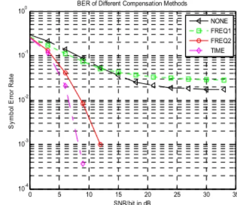
1. Recovered constellations by three different compensation methods, where SNR=23 dB, =0.15, are shown in Fig 2.
The results of no compensation, compensation in frequency domain by S , compensation in frequency domain based on equation (13) and compensation in time domain are designated by ‘NONE’,’Freq1’,’Freq2’ and ‘Time’
respectively. For the constellation figure compensated by S
, dispersion level appears even greater than that of the non-compensated one because the randomness of adjacent carriers are superposed in the process of matrix multiplication, nevertheless the constellation center is corrected. Only the time domain method can correct angular disposition as well as the dispersiveness of the constellation as can be noticed in the Fig 2. In Fig 3, BER performance of three different compensation methods are presented for is equally assumed 0.15. The simulation results of Fig. 3 are just reconfirmation of the rationale behind the simulation results of Fig. 2. As mentioned in other research activity in reference [1], saturated BER lower bound can be noticed in none compensation as well as the case of compensation by S . From the simulation results, practical BER requirements may not be met without adequate compensation techniques in some ranges of and the proposed compensation methods can be a simple but effective measure to solve the problem. Through the simulation, the theoretical derivation of the paper are proved so some of schemes can be successfully adopted to compensate Doppler effect distortion of OFDM system.
-2 -1.5 -1 -0.5 0 0.5 1 1.5 2
-2 -1.5 -1 -0.5 0 0.5 1 1.5
2 Constellation for different frequency offset
-0.06 0.04 0.11 0.19 0.26
Fig.1. Constellation of Different Doppler Frequncy offset
-2 -1.5 -1 -0.5 0 0.5 1 1.5 2
-2 -1.5 -1 -0.5 0 0.5 1 1.5
2 Constellation for different compensation algorithm
NONE Freq1 Freq2 Time
Fig. 2. Constellation for Different Compensation Schemes
0 5 10 15 20 25 30 35
10-4 10-3 10-2 10-1 100
Symbol Error Rate
SNR/bit in dB BER of Different Compensation Methods
NONE FREQ1 FREQ2 TIME
Fig. 3. BER of the different Compensation Schemes
References
[1] Y.Zhao and S.G. Haggman.:’BER Analysis of OFDM Communication System with Intercarrier interference’. Proc.
Int. Conf. on Communication Technology. October 22-24,1998, Beijing,China,S38-02-1-5
[2] Van Nee and Prasad.:’OFDM For Wireless Multimedia Communications’ Artech House Publishers, 2000.
[3] Y.Zhao and S.G. Haggman.:’Intercarrier Interference Self-Cancelling Scheme for OFDM Mobile Communication Systems’ IEEE Trans. On Comm. Vol49, July 2001, pp1185-2001
[4] T. Yusek and H. Arslan.:’ICI cancellation based channel estimation for OFDM systems’.Proc. of Radio and Wireless Conf. 2003, Aug. 2003 pp 111-114
[5] P. Schniter.:’Low-Complexity Equalization of OFDM in Doubly Selective Channels’. IEEE Trans. On Signal Proc.
Vol.52, No.4, April. 2004, pp1002-1011
한국위성정보통신학회논문지 제12권 제2호
82
Author
Byung-Seub Lee
received the BS degree from Korea Aerospace University in 1979, the MS degree from Seoul National University in 1981, and the PhD degree from New Jersey Institute of Technology in 1990. He was a head of TT&C section of Satellite Communication System Department at Electronics and Telecommunications Research Institute (ETRI), KOREA from 1990 to 1992. Since 1992, he has been a Professor of Department of Information and Telecommunication Eng. Dept. of Korea Aerospace university. Currently he is Head of School of Avionics , Telecommunication and Computer Eng. Of Korea Aerospace university and also president of Telecommunication and Broadcasting Technology Lab. He is now working as a Pesident of Korea Society of Space Technology (KOSST) from 2017. His research areas are satellite communications, Adaptive antenna array and signal processing, Bio radar and active noise control.