Minimizing the power consumption of ZigBee RF4CE Certified Platform
Taek-Soo Jung* , Jung-Won Kim**
★
Abstract
The RF4Control stack is used with microcontrollers and IEEE® 802.15.4 transceivers. This paper explains the setup and power consumption measurements for the transceiver based remote controller and target node. It is assumed the reader of this paper has knowledge about RF4CE. The current consumption measurements are made using the ZigBee Platform included with the RF4Control stack. he current consumption measurements are presented, and battery life time is calculated for an remote controller. Note that the results presented in this paper are intended as a guideline only. A variety of factors will influence the battery life calculation and final measurements and calculations should be performed on ZigBee RF4CE Certified Platform.[1],[2]
Key words: RF4CE, ZigBee, power consumption, topology, RC
* Dept. of Information Communication, Kwangwoon University
** Electrical Engineering, Korea Polytechnic University
★Corresponding author
Manuscript received Sep. 14, 2011;Revised Nov. 29, 2011 Accepted Dec. 03. 2011
Ⅰ. Introduction
In 2009 the RF4CE (Radio Frequency for Consumer Electronics) Consortium and ZigBee Alliance agreed to jointly deliver a standard for radio frequency remote controls. ZigBee RF4CE is designed for a wide range of consumer electronics products, such as TVs and set-top boxes. It promises many advantages over existing remote control solutions, including richer communication and increased reliability, enhanced features and flexibility, interoperability, and no line-of-sight barrier.[3]
It provides a multi-vendor interoperable remote control solution for consumer electronics featuring a simple, robust and low-cost communication network for two-way wireless connectivity.
Unlike many of today’s RF remote controls that require the use of an intermediary base station
receiver, ZigBee RF4CE is designed to be built into the consumer electronics devices themselves. This makes it an ideal technology for two-way communication between the device and remote.
This paper was characterized by showing the method to calculate battery life by measuring current consumption. Therefore, it will be possible to minimize power consumption, and it is also expected to help method of measuring the power consumption in other transceivers.
ZigBee RF4CE uses a star topology, and was designed specifically for applications requiring simple device-to-device control communication that do not need the full-featured mesh networking capabilities offered by protocols such as ZigBee. It offers lower memory size requirements, which enables lower-cost implementations. The simple device-to-device topology provides easy development and testing to enable faster time to market.
Possible uses for ZigBee RF4CE include entertainment devices, garage door openers, and keyless entry systems. The composition of this paper is given below. The second chapter explained
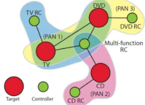
Fig 1. Example RC network topology about RC network and nodes of network topology,
the third chapter showed the method of measuring active current through Agilent Oscilloscope, and the fourth chapter showed the current consumption of RC based on the method of measuring the Active Current. The final chapter ended up describing the conclusion of this measurement.[4],[5]
Ⅱ. Network topology
RC PAN nodes can talk to the two types. The first one is the full-function device(FFD). It can serve as the coordinator of a personal area network just as it may function as a common node. It implements a general model of communication which allows it to talk to any other device: it may also relay messages, in which case it is dubbed a coordinator (PAN coordinator when it is in charge of the whole network). On the other hand there are reduced-function devices(RFD). These are meant to be extremely simple devices with very modest resource and communication requirements; due to this, they can only communicate with FFD's and can never act as coordinators.
An RC PAN is composed of two types of device:
a target node and a controller node. A target node has full PAN coordinator capabilities and can start a network in its own right. Both types of node can join networks started by target nodes by pairing with that target. Multiple RC PANs form an RC network and nodes in the network can communicate between RC PANs.
In order to communicate with a target node, a controller node first switches to the channel and assumes the PAN identifier of the destination RC PAN. It then uses the network address, allocated through the pairing procedure, to identify itself on the RC PAN and thus communicate with the desired target node.
Fig.1 illustrates an example ZigBee RF4CE topology which includes three target nodes: a TV, a DVD and a CD player and each target node creates its own RC PAN. The TV, DVD and CD player also have dedicated RCs which are paired to each appropriate target node. A multi-function RC, capable of controlling all three target nodes itself, is
added to the network by successively pairing to the desired target nodes. The DVD is also paired with the TV so that an external channel can be selected
on the TV when a DVD is played.
As a consequence, this RC network consists of three separate RC PANs: one managed by the TV (PAN1), containing the TV RC, the multi-function RC and the DVD; a second managed by the CD player (PAN 2), containing the CD RC and the multi-function RC and a third managed by the DVD (PAN3), containing the DVD RC, multi-function RC and the TV.[5],[6],[7]
Ⅲ. Measurement
An Agilent Oscilloscope is used to capture the current waveform components. The voltage
across a 10Ω resistor (±2%) is captured, and hence the current draw is 1/10 of the captured voltage.
The setup in is shown in Fig.2[8]
Fig 2. RC Active Current Measurement Setup 3.1 Active Current Measurement
3.1.1 RC Component Measurement
It is important that the RC consumes as little current as possible to enable long battery life. The RC is in deep sleep mode as much as possible and
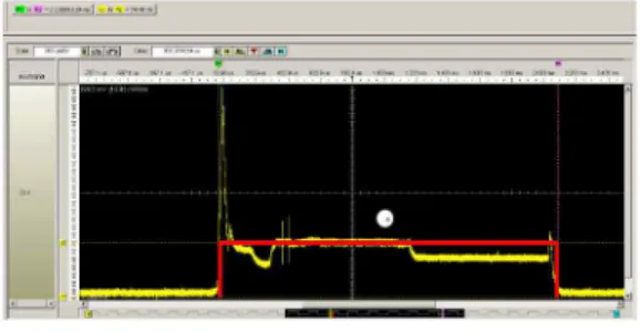
Fig 4. RC TX w/ACK Current Waveform Fig 3. RC Current Waveform
RC Average Current Consumption
Events Time Current Time*Current
Wake-up sequence, timer configuration, power mode 2.11 ms 7.45 mA 15.72 mAms
Total 2.11 ms 15.72 mAms
TX w/ACK Component Average Current Consumption
Events Time Current Time*Current
1.Wake-up sequence, key processing 4.14 ms 7.72 mA 31.96 mAms
2. CCA, radio in RX 0.62 ms 26.90 mA 16.60 mAms
3. RX/TX switch 0.19 ms 14.34 mA 2.68 mAms
4. TX 0.94 ms 35.47 mA 33.27 mAms
5. TX/RX switch 0.06 ms 14.34 mA 0.79 mAms
6. Wait for ACK, radio in RX 0.77 ms 26.90 mA 20.79 mAms
7. Processing and power down
sequence to deep sleep mode 0.35 ms 7.72 mA 2.72 mAms
Total 7.06 ms 108.81 mAms
wakes up on a key press to process the input and send the message over-the-air. In order to avoid input jitters when a key is pressed, the device wakes up on a key press and sets the sleep timer to expire in 25ms and enters Power Mode. At this point we need to be in Power Mode since the sleep timer is running. Fig.3 shows the current waveform for the remote control.
The current consumption for the RC is summarized in Table 1.
3.1.2 TX w/ACK Component Measurement
After the ACK is received, the RC configures the sleep timer to expire in 50 ms and enters power
mode. At timer expiration, the RC checks if the key is still pressed. It sends a CERC(Consumer Electronics Remote Controller) control repeated’
command if the key is still pressed, configures the sleep timer to expire in 50 ms and enter power mode again. This will repeat until the key is release upon which the RC sends a CERC control released’
command and enters deep sleep mode.
A CERC control pressed/repeated/released’
command exhibit the same current waveform characteristics. Only the payload content of the messages will be different. Thewaveform in Fig.4 shows a successful TX w/ACK component based on either of the CERC commands.
The current consumption for the TX w/ACK(One message sent over-the-air with ACK received from the target node) component is summarized in Table 2.
Table 1. RC Average Current Consumption
Table 2. RC TX w/ACK Component Average Current Consumption
Fig 5. RC TX w/o ACK Current Waveform
Active Mode Current Consumption Events Time*Current Comments 1. RC Components 15.72 mAms From Table 1 2. TX w/ACK 108.81 mAms From Table 2
Total 124.53 mAms
TX w/o ACK Component Average Current Consumption
Events Time Current Time*Current
1. CCA, radio in RX 0.58ms 26.92 mA 15.56 mAms
2. RX/TX switch 0.18 ms 14.68 mA 2.64 mAms
3. TX 0.94 ms 35.60 mA 33.39 mAms
4. TX/RX switch 0.06 ms 14.68 mA 0.92 mAms
5. Wait for ACK, radio in RX 0.88 ms 26.92 mA 23.77 mAms
6. Processing 0.13 ms 14.68 mA 1.95 mAms
Total 2.78 ms 78.24 mAms
3.1.3 TX w/o ACK Component Measurement A RC sending a message to a target node in standby mode should use the unicast, multichannel,ACKed TX option as explained in section 4.1. This ensures the RC continuously repeats the message for nwkcMaxDutyCycle or until the target node receives and ACKs the message.
Fig.5 shows the waveform when the RC is repeating the message without receiving the ACK.
The current consumption for the TX w/o ACK(One message sent over-the-air without an ACK received from the target node) component is summarized in Table 3.
3.2 Sleep Current Measurement
The RC spends majority of its time in deep sleep.
The setup in Fig.6 is used to measure the sleep current of the RC. We are using an ampere-meter for this measurement since the current is very low.
Fig 6. RC Sleep Current Measurement Setup
Ⅳ. RC Current Consumption
4.1 active mode
The target receiver is always turned on when in active mode. The assumption is therefore that a message sent by the RC is ACKed within a short time. No assumptions are made with respect to a compromised channel triggering message retries.
The RC active mode current consumption is comprised of the key de-bounce component and one TX w/ACK component as shown in Table 4.
Table 4. RC Active Mode Current Consumption
Table 3. RC TX w/o ACK Component Average Current Consumption
Fig 7. RF4CE Target Node Active Period and Duty Cycle
Standby Mode Current Consumption
Events Time*Current Comments
1. RC Components 15.72 mAms From Table 1
2. TX w/o ACK 4 415.42 mAms From Table 3 * 56 retries
on average
3. TX w/ACK 108.81 mAms From Table 2
Total 4 539.95 mAms
System Number
of units Standby mode
key presses Active mode key presses
Standby mode current consumption
Active mode current consumption
TV 1 2 50 9,080 mAms 18,679 mAms
Receiver 1 2 100 9,080 mAms 37,359 mAms
DVD/Blu-ray 1 1 20 4,540 mAms 7,472 mAms
Cable/Satellite 1 0 100 0 mAms 37,359 mAms
Active Current 0 0 0 22,700 mAms 100,869 mAms
Active Total 123,569 mAms
Sleep Total 34,560 mAms
Total Power
consumption 158,129 mAms
4.2 Standby Mode
The target receiver is duty cycling when in standby mode. The message sent by the RC is therefore likely to be repeated multiple times before an ACK is received. The assumption is the target will respond to the message within a short time after enabling its receiver. The RF4CE specification dictates the active period nwkActivePeriod >
(nwkcMinActivePeriod=16.8ms) and the duty cycle nwkDutyCycle < (nwkcMaxDutyCycle =1s). This is illustrated in Figure7.
The RC is configured with nwkDutyCycle= 300 ms. This means the receiver is turned off for
nwkDutyCycle – nwkcMinActivePeriod = (330 – 16.8)ms
Elapsed time for each TX w/o ACK component is 2.78 ms as seen in Table 3. Statistically, it is reasonable to assume a uniform distribution such that the number of TX attempts to wake up the target node from standby mode on average is (330 -16.8) ms / 12.78 ms x 0.5 = 56.
The standby mode current consumption is comprised of the key de-bounce component, the statistically averaged number of TX w/o ACK components and the TX w/ACK component as shown in Table 5.
A RC is application specific in terms of how many target nodes it controls, number of messages sent when the target is in standby mode and in active mode. This paper assumes a RC where the RC is controlling four target nodes with the following occurrences per day.
In order to calculate the total average current consumption for the example RC, we need to summarize the RC sleep, active mode and standby mode contributions for one day as seen in Table 6.
Table 5. RC Standby Mode Current Consumption
Table 6. RC Total Average Current Consumption per Day
Ⅴ. Conclusion
This paper showed that the power consumption of each node was known by the method of measuring the Active Current and Sleep Current.
This paper has illustrated the power consumption for the RF part of a RC is very small. In fact, the self discharge of a typical alkaline battery is about 1uA. The self discharge is therefore about 50% of the current consumption for the usage model described in this paper. Other system components e.g. LED, backlight, LCD etc. will likely be the major contributors to an RC total current consumption.
References
[1] IEEE Standard 802.15.4TM-2006: Wireless Medium Access Control (MAC) and Physical Layer (PHY) Specifications for Low-Rate Wireless Personal Area Networks (WPANs) [2] The Institute of Electrical and Electronics Engineers, Inc., IEEE Std. 802.15.4-2006, IEEE Standard for Information Technology.
Telecommunications and Information Exchange between Systems. Local and Metropolitan Area Networks. Specific Requirements. Part 15.4:
Wireless Medium Access Control (MAC) and Physical Layer (PHY) Specifications for Low Rate Wireless Personal Area Networks (WPANs). New York: IEEE Press. 2006.
[3] http://standards.ieee.org/getieee802/download/
802.15.4-2006.pdf
[4] http://en.wikipedia.org/wiki/RF4CE
[5] http://www.daintree.net/downloads/whitepapers/
zigbee-rf4ce-intro.pdf
[6] ZigBee RF4CE Specification (ZigBee Alliance document 094945r00ZB)
[7] Roberts, Lawrence G.; Wessler, Barry D. (1970),
"Computer network development to achieve resource sharing", AFIPS '70 (Spring):
Proceedings of the May 5–7, 1970, spring joint computer conference, New York, NY, USA:
ACM, pp. 543–549, doi:10.1145/1476936.1477020 [8] http://focus.ti.com/docs/prod/folders/print/
cc2530.html
BIOGRAPHY Taek-soo Jung (Student Member)
2009 : BS degree in Electrical Engineering, Korea Polytechnic University.
2009 ~ : MS degree in Information Communication, Kwangwoon University.
Jung-won Kim (Member)
2002 : BS degree in Electrical Engineering, Korea Polytechnic University.
2004 : MS degree in Electrical Engineering, Korea Polytechnic University.
2009 : PhD degree in Electrical Engineering, Korea Polytechnic University 2001~2004 : Research Engineer, Namsong Ind.
2004~ : Research Engineer, Changnam I.N.T 2007~ : Adjunct Professor, Electrical Engineering, Korea Polytechnic University.