Address: 7-3-1 Hongou, Bunkyou-ku, Tokyo, JAPAN 113-8656 [email protected]
Keywords: Hall Thruster, Thrust Vector Control, Discharge Current Oscillation Abstract
In order to achieve thrust vector control and discharge stabilization in Hall thrusters, the azimuthal nonuniformity of propellant flow rate in an acceleration channel was created. A plenum chamber was divided into two rooms by two walls and propellant flow rate supplied to each section was independently controlled. In a magnetic layer type Hall thruster, steering angle of up to ±2.3 degree was achieved. In an anode layer type Hall thruster, discharge current oscillation amplitude was decreased with the normalized differential mass flow rate.
Introduction
A Hall thruster is one of the most attractive propulsion devices for near-Earth missions because of its high thrust efficiency at the specific impulse in the range of 1,000-3,000 s. Though there are several types of Hall thruster, they are categorized generally into two groups: magnetic layer type and anode layer type.1) The former has been used in many missions2-3) and the latter is under development because of difficulty of stable operation. As key technologies to improve their adaptability to future missions, thrust vector control was proposed for the magnetic layer type and discharge stabilization for an anode layer type by controlling mass flow uniformity in their annular acceleration channels.
Thrust vector control is important for fulfillment of near-Earth missions such as orbital transfer. So far, mechanical gimbal systems4-5) have been used as steering devices and played a broader role not only in large thrust deviation for orbital transfer but also in small thrust deviation for adjustment of mounting angle and moment release of reaction wheels.
However, this system has several problems, e.g.
heaviness and complexity.5) Gimbals bring about increase in bus system mass and decrease in reliability because of high failure probability in many mechanical components. Hence, development of a steering system without mechanical structures is desirable.
In electric propulsion devices, a Hall thruster has the most promising characteristics6-7) to achieve thrust vector control by artificially creating azimuthal nonuniformity of magnetic flux density and propellant flow rate in its annular channel. In the thrust vector control by magnetic flux density nonuniformity, steering is achieved by distorting magnetic lines of
force to be perpendicular to target thrust direction. On the other hand, by propellant flow rate nonuniformity, steering is achieved by the difference in radial thrust component. Thus, there are two approaches and their combination for thrust vector control. In this study, the azimuthal nonuniformity of propellant flow rate was created by a segmented plenum chamber, and steering angle was measured.
The other subject in this paper is discharge stabilization of an anode layer type Hall thruster. This type thruster has high thrust efficiency because its short channel length and metal channel wall decrease energy loss toward the channel wall.1) However, its operation is unstable due to the discharge current oscillation8-9) and limited in a narrow range of operational parameters. Particularly, the oscillation at the frequency range of 10-100 kHz has large amplitude and causes harmful effects on Hall thruster operation. Operation in unstable region has the possibility that the discharge current oscillation grows up and Hall thruster’s operation is stopped. In addition, this oscillation increases the ratio of maximum discharge current to the average, which brings about increase in the weight of power supply unit, that is, decrease in the ratio of thrust to propulsion system mass. Thus unstable operation leads to low reliability and decrease in mission payload mass.
Figure 1 shows typical discharge oscillation characteristics. Here, oscillation amplitude ∆ is defined as
2
0( )
1 d d
d
I I dt
I
τ
τ
∆ = ∫ −
(1) where τ is measurement duration. Threshold magnetic flux density exists at 12 mT and divides discharge characteristics into stable and unstable regions. For magnetic flux density greater than 16 mT, operation is impossible due to the rapid growth of discharge current oscillation. Although operation is stable for magnetic flux density less than that threshold, average discharge current increases steeply with decrease in magnetic flux density, which also leads to enlargement of the power supply margin, that is, increase in its weight. Therefore, in order to take advantage of the high thrust efficiency of anode layer type thrusters, it is necessary to widen the stable region with low gradient of average discharge current.
In this study, as another effect achieved by azimuthal nonuniformity of propellant flow rate, discharge stabilizing effect was investigated.
0 5 10 15 20 0
1 2 3 4 5 6
0.01 0.1 1 10
Magnetic flux density, mT
Average discharge current, A Oscillation amplitude
Fig. 1 Discharge oscillation characteristics of our anode layer type thruster with hollow anode at the typical condition that discharge voltage and xenon mass flow rate are 250 V and 1.63 mg/s.
Experimental Apparatus Hall Thrusters
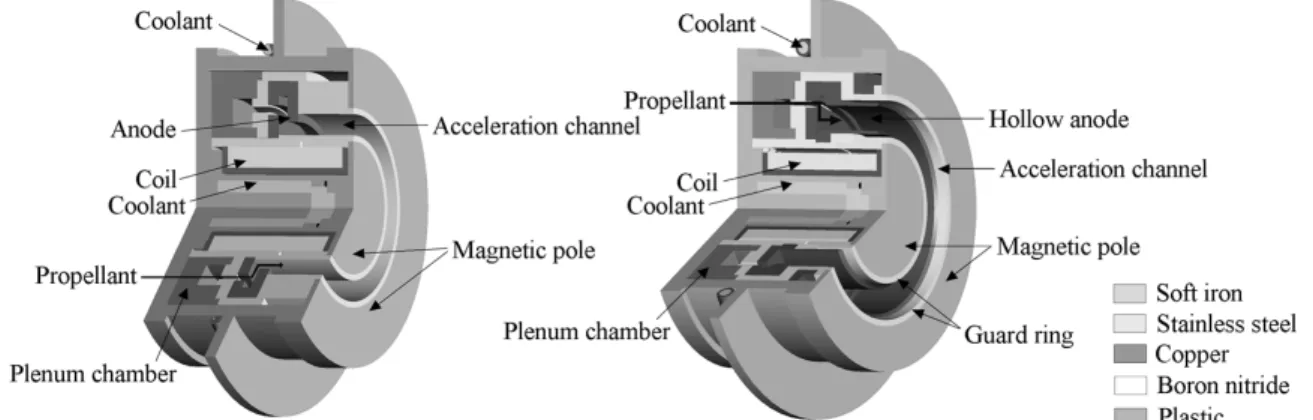
Figure 2 shows the cross sections of magnetic layer type and anode layer type Hall thrusters. Both thrusters have the same inner and outer diameter of acceleration channel which are 48 and 62 mm, respectively. The magnetic layer type thruster has acceleration channel made of boron nitride and the channel length is 21 mm. The guard rings of anode layer type are made of stainless steel. A hollow shape anode with the hollow width of 3 mm and anode-tip- to-thruster-exit distance of 3 mm was used. This configuration is the most effective one for discharge stabilization according to the past study.10) Magnetic circuit structure and water cooling system are common in both thrusters. Magnetic field in the acceleration channel is generated by a solenoidal coil on the thruster’s central axis. Hollow cathode was used and xenon gas was supplied to it at 0.27 mg/s.
Figure 3 shows a plenum chamber divided into two right-and-left rooms by two walls. Xenon gas was used as a propellant and supplied to each room through two ports on the back surface of the thruster.
Xenon flow rate through each port was independently controlled by two mass flow controllers.
Fig. 3 A segmented plenum chamber.
Vacuum Chamber
The vacuum chamber whose diameter and length are 2.0 and 3.0 m was used in this study. The pumping system comprises three pumps: a diffusion pump (37000 l/s), a mechanical booster pump (10000 m3/h) and two rotary pumps (15000 l/min).
Thrust Stand
In order to measure two components of thrust vector, a two-axis dual pendulum thrust stand11) was used. This thrust stand has two pendulums and four arms per pendulum. All joints between any two components consist of knife-edges and supporting point of each arm consists of two orthogonal knife- edges. Pendulums can move in the two directions:
axial and transverse direction of a thruster. A thruster and sensor targets are mounted on the inner pendulum and two displacement sensors are set on the outer pendulum. The thermal influence from a Hall thruster is cancelled out by those pendulums. Because this thrust stand is the type put on the chamber, it is hardly affected by the chamber oscillation. According to the thrust calibration by weights, measurement errors were less than 0.25 mN in the axial direction and 0.09 mN in the transverse direction.
Discharge Current Measurement Systems
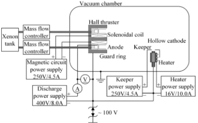
Figure 4 shows a schematic diagram of measurement system. In order to measure discharge current, 0.5 Ω metal-film resistor was inserted between anode and discharge power supply and the voltage between its both ends was measured by an oscilloscope with a differential probe.
Fig. 2 Magnetic layer type (left) and anode layer type (right) Hall thrusters developed at the University of Tokyo.
Fig. 4 Power supply and measurement system.
Thrust Vector Control Simplified Model
When we consider the case that all parameters except propellant flow rate, e.g. magnetic field are uniform in the azimuth direction and the radially- integrated velocity vector of exhausted ions has radial component, the steering by azimuthal nonuniformity of propellant flow rate can be explained as follows.11) If the ion exhaust velocity vector averaged over the right-and-left half Vion is inclined at the plume convergent angle θ from axial direction toward the thruster’s central axis (Fig. 5), the axial and transverse (leftward) thrust Taxial, Ttransverse are
axial right left right left ion
transverse right left right left ion
( ) cos ( ) cos
( ) sin ( ) sin
T T T m m
T T T m m
θ θ
θ θ
= + = +
= − = −
ɺ ɺ
ɺ ɺ
V
V (2)
where Tright, Tleft, mɺrightandmɺleftare the thrusts derived from the right-side and left-side ions and propellant mass flow rates through the right and left ports. Here, for simplicity, the following assumptions were used:
(1) 100% ionization; (2) no azimuthal diffusion of neutrals and ions; and (3) Vion and θ are constant in any azimuthal distribution of propellant flow rate.
The normalized differential mass flow rate K is defined as
right left
difference
total right left
m m
K m
m m m
= = −
+
ɺ ɺ
ɺ
ɺ ɺ ɺ (3)
The leftward steering angle α is
right left
transverse
axial right left
tan T m m tan tan
T m m K
α = = − θ = θ
+
ɺ ɺ
ɺ ɺ (4)
If α, θ << 1, Eq. (4) becomes α ≈ Kθ. Hence, steering angle α has the linear relation with K and its upper limit is θ.
Experiment
In the magnetic layer type thruster, K was changed at the interval of 0.5 and the axial and transverse thrusts were measured. The discharge voltage, total xenon mass flow rate and magnetic flux density were 300 V, 1.36 mg/s and 20 mT, respectively. During the experiment, the background pressure was kept at 1.6×10⁻² Pa.
right
mɺ mɺleft
transverse
T
Fig. 5 Simplified model of thrust vector control.
Discharge Stabilization Experiment
In order to investigate the influence of azimuthal nonuniformity of propellant flow rate on discharge characteristics in the anode layer type thruster, K was changed at the interval of 0.2. Total xenon flow rate and discharge voltage were 1.63 mg/s and 250 V, respectively. At each K, magnetic flux density to which discharge characteristics is the most sensitive was changed at the interval of 16 mT and 5 ms data of discharge current was collected at the sampling rate of 10 MHz. Throughout the measurement, the background pressure was kept at 3.8×10⁻³ Pa.
Results and Discussion Thrust Vector Control
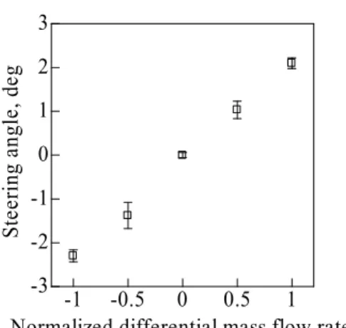
Figure 6 shows the axial and transverse thrust at each normalized differential mass flow rate K. The error bars stand for standard deviation over 5 measurements. Figure 7 shows the relation between K and steering angle α.
Steering angle of up to ±2.3 deg was achieved. As expected in the above model, α had linearity related to K and increase in the right-side xenon flow rate brought about the leftward thrust. The plume convergent angle θ was about 2.3 deg because the maximum value of α was 2.3 deg. Though the axial and total thrust was increased by azimuthal nonuniformity of xenon flow rate as shown in Fig. 6, the thrust efficiency slightly decreased due to increase in discharge current.
-1 -0.5 0 0.5 1
10 15 20
-1 -0.5 0 0.5 1
Normalized differential mass flow rate
Axial thrust, mN Transverse thrust, mN
Fig. 6 Axial and transverse thrust.
-1 -0.5 0 0.5 1 -3
-2 -1 0 1 2 3
Normalized differential mass flow rate
Steering angle, deg
Fig. 7 Relation between normalized differential mass flow rate K and steering angle α.
Discharge Stabilization
The influence of azimuthal nonuniformity of xenon flow rate on the discharge characteristics appeared for normalized differential mass flow rate K
≥ 0.6. Figures 8-12 show the results. The upper limits of magnetic flux density stand for the operational limit. At K = 0.0 and 0.6, the operation was stopped by the growth of discharge current oscillation. At K = 0.8 and 1.0, it was stopped by too low electron mobility, independently of discharge current oscillation. On the other hand, the lower limit was decided by the current capacity of the power supply used in this experiment.
As shown in Fig. 8, discharge current oscillation amplitude decreased with K. The maximum oscillation amplitude decreased by up to 66%
compared to the normal operation K = 0.0. In addition, in K ≥ 0.8, the operation range spread toward high magnetic flux density side and the second stable region appeared. As K increased, its range became wider and the oscillation amplitude further decreased.
The value of magnetic flux density to make the operation unstable was not affected by azimuthal nonuniformity and was in the range of 12-20 mT. In the region with low magnetic flux density, the oscillation amplitude once increased at K = 0.6 and 0.8 where the second stable region began to appear.
The average discharge current increased with K.
0 0.2 0.4 0.6 0.8 1 0.1
1 10
Normalized differential mass flow rate
Maximum oscillation amplitude
Fig. 8 Maximum oscillation amplitude at each K.
0 10 20 30 40 50 60 0
1 2 3 4 5 6 7
0.01 0.1 1 10
Magnetic flux density, mT
Average discharge current, A Oscillation amplitude
Fig. 9 Discharge characteristics at K = 0.0.
0 10 20 30 40 50 60 0
1 2 3 4 5 6 7
0.01 0.1 1 10
Magnetic flux density, mT
Average discharge current, A Oscillation amplitude
Fig. 10 Discharge characteristics at K = 0.6.
0 10 20 30 40 50 60 0
1 2 3 4 5 6 7
0.01 0.1 1 10
Magnetic flux density, mT
Average discharge current, A Oscillation amplitude
Fig. 11 Discharge characteristics at K = 0.8.
0 10 20 30 40 50 60 0
1 2 3 4 5 6 7
0.01 0.1 1 10
Magnetic flux density, mT
Average discharge current, A Oscillation amplitude
Fig. 12 Discharge characteristics at K = 1.0.
deg was achieved and the steering angle had the linear relation with the normalized differential mass flow rate. Though the total thrust was increased by azimuthal nonunifomity of xenon flow rate, the thrust efficiency slightly decreased because of discharge current increase.
In an anode layer type thruster, discharge current oscillation amplitude decreased with the normalized differential mass flow rate. The maximum oscillation amplitude decreased by up to 66% compared to the normal operation. Additionally, in the case that xenon flow rate has strong nonuniformity in the azimuth direction, the wide-range stable region that discharge characteristics are not sensitive to magnetic flux density appeared at high magnetic flux density. In order to understand this discharge stabilization effect, time-varying model of azimuthal nonuniformity and further experiments related to various distribution profiles are necessary.
Acknowledgement
The present work was supported by a Grant-in- Aid for Scientific Research (S), No. 16106012, sponsored by the Ministry of Education, Culture, Sports, Science and Technology, Japan.
References
1) Choueiri, Y. E.: Fundamental Difference between the Two Hall Thruster Variants, Physics of Plasmas, 8 (11), 2001, pp. 5025-5033.
2) Koppel, R. C., and Estublier, D.: The SMART-1 Hall Effect Thruster Around the Moon: In Flight Experience, The 29th International Electric Propulsion Conference, 2005, 119.
3) Ozaki, T., Kasai, Y., Inanaga, Y., Nakagawa, T., Osuga, H., Itoh, T., Kajiwara, K., and Matui, K.:
Electric Propulsion Development Activity at MELCO, AIAA Paper 2006-4321.
4) Duchemin, O., Illand, H., Saverdi, M., Cesari, U., Signori, M., Pagnon, D., and Estublier, D.:
Testing of a Thrust Steering Device on the PPS®1350 Hall Thruster, AIAA Paper 2006-4478.
5) Biron, J., Cornu, N., Illand, H., Serrau, M., Rigollet, R., and Gray, L. H.: The Thruster Module Assembly (Hall Effect Thruster) design, qualification and flight, The 29th International Electric Propulsion Conference, 2005, 213.
6) Yashnov, M. Y., Koester, K. J., McVey, B. J., and Britt, J. E.: The Optimal Control of Thrust Vector of Hall-thrusters, The 26th International Electric Propulsion Conference, 1999, 123.
1411-1426.
9) Yamamoto, N., Komurasaki, K., and Arakawa, Y., Discharge Current Oscillation in Hall Thrusters, Journal of Propulsion and Power, 21 (5), 2005, pp. 870-876.
10) Yamamoto, N., Komurasaki, K., and Arakawa, Y.: Condition of Stable Operation in a Hall Thruster, The 28th International Electric Propulsion Conference, 2003, 086.
11) Nagao, N., Yokota, S., Komurasaki, K., and Arakawa, Y.: Development of a Two-axis Dual Pendulum Thrust Stand for Thrust Vector Measurement of Hall Thrusters, The 30th International Electric Propulsion Conference, 2007, 098.