* Corresponding Author : [email protected]
+ 이 논문은 교육부와 한국 연구재단의 지역혁신인력 양성사업 으로 수행된 연구결과임.
Manuscript received September 21, 2017 / revised December 18, 2017 / accepted December 26 2017
1) 창원대학교 전기공학과, 제1저자 2) 창원대학교 전기공학과, 제2저자 3) 창원대학교 전기공학과, 제3저자 4) 창원대학교 전기공학과, 교신저자
유목민들을 위한 PV & Battery용 DC-DC 컨버터의 통합제어 알고리즘
(Combined Control Algorithm for a DC-DC Converter of PV & Battery for Mongolian Nomadic Life)
투덴수런 오운자르갈1), 레 덧 탕2), 박 민 원3), 유 인 근4)*
(Oyunjargal Tuvdensuren, Tat-Thang Le, Min-Won Park, and In-Keun Yu)
요 약 독립형 태양광(PV) 시스템은 몽골 유목민 목축업자들에게 가장 중요한 에너지발전 시스 템 중 하나이다. 기본적으로 독립형 PV 시스템은 두 개의 DC-DC 컨버터를 사용한다. 이 시스템은 비용이 많이 들고, 사이즈가 커지기 때문에 다른 장소로 이동 할 때 큰 어려움이 있다. 본 논문에서 는 배터리의 SOC 제어 와 최대전력추종제어가(MPPT) 결합된 제어 알고리즘을 제안한다. 배터리는 3단계(Bulk, Absorption, Float Charge)로 충·방전된다. 본 논문에서는 Bulk단계에서 MPPT제어 기 반으로 충전되는 제어 알고리즘을 제안한다. 제안된 제어 알고리즘을 다양한 날씨 조건에 대해서 적 용하였으며, PSIM 소프트웨어를 이용한 시뮬레이션을 통하여 그 효용성을 검증하였다. 본 논문에서 제안한 알고리즘은 몽골 유목민들의 농촌 생활에 필수적인 독립형 태양광 발전 시스템을 설계하는 데 유용하게 사용될 것이다.
핵심주제어 : 배터리 충전, DC-DC 부스트 컨버터, MPPT, 태양광
Abstract A stand-alone Photovoltaic (PV) system is one of the most important energy system for Mongolian nomadic herders. Basically, a stand-alone PV system uses two DC-DC converters. This makes the system costly, size bigger and difficult to move from one place to another place for the nomadic herders. A combined control algorithm for charging the battery using Stage of Charge (SOC) and Maximum Power Point Tracking (MPPT) is proposed in this paper. The batteries are charged by the three stage method; bulk, absorption and float charge.
In the bulk stage used the MPPT function in this study. The performance of the proposed control algorithm is evaluated in both steady and changing weather conditions. The results are obtained using PSIM software. The results obtained in this paper are useful in designing a stand-alone PV system in the rural life like Mongolian nomadic herders.
Key Words : Battery Charger, DC-DC Boost Converter, MPPT, Photovoltaic
1. Introduction
Mongolia is a geographically large but sparsely populated country. The covering area is 1,564,116 km, with a population of 3 million people. About 1.3 million of Mongolia’s citizens live in the urban capital of Ulaanbaatar, while the remaining population is widely dispersed through out the country with a large number residing in rural areas. In total, about a quarter of the population consists of nomadic herders. In other words, about 800,000 of 3 million herders are still living in the traditional nomadic life style[1]. Therefore, the stand-alone photovoltaic (PV) system is one of the most important energy systems for Mongolian nomadic herders. Because the herders move from one place to another to graze fields for livestock in every seasons with their homes (which is called the “ger”), they mostly use a stand-alone PV system that generates electricity for 12 V, 24 V televisions and washing machines, lighting, food refrigeration and charging phones. Basically, the stand-alone PV system uses two DC-DC converters. One DC-DC converter is controlled by maximum power point tracking (MPPT) and another one for charging the battery [2-3].
This makes the system costly, big size and difficult for reparation and moving especially by the nomadic herders.
This paper targets the performance enhancement of one DC-DC boost converter for both charging battery and MPPT control for nomadic life. A combined control algorithm for the Stage of Charge (SOC) battery and MPPT is proposed. In the proposed control system the DC-DC converter used the boost topology with advantage of small input current
ripple. The batteries are, in general, charged by the three stage method; bulk charge, absorption charge and float charge. The bulk charge is replaced by the MPPT function in this paper. The SOC determination method is used which helps the converter charge the battery quickly, safely and properly[4].
The authors simulated the performance of the system considering SOC with MPPT. The simulation is executed by using PSIM software. The simulation equivalent circuit consists of a single PV panel, two batteries connected in series and one DC-DC converter.
The detailed explanations and results were discussed in detail.
This paper is organized as follows: in the second section presents a brief review of the operation, principles of whole system and details about the proposed system are given;
in the third section presented the simulation and the results, and finally the conclusions are followed.
2. Combined Control Algorithm 2.1 Configuration of the PV System
In general a stand-alone PV system uses two DC-DC converters. One converter is controlled by MPPT, and another one for charging the battery. But nomadic herders use loads under the same voltage level as is the battery supply. So the authors suggested omission of one DC-DC converter and hence the size and cost reduced. A DC-DC converter controls both of MPPT and charging battery through DC-link voltage in the system.
The proposed system as is shown in Fig. 1
consists of a single PV panel, two lead acid batteries connected in series and one DC-DC converter for charging batteries and tracking maximum power point with 24 V DC link. The DC-DC converter used the boost topology with advantage of small input current ripple. In the proposed control algorithm, the Perturb and Observe (P&O) method MPPT algorithm defines the current level lower than the initial charging current [5]. During the day time, the system stores energy from PV panel in the battery [4]. Loads use energy from PV and battery through the DC link. During a period of low solar irradiance, such as a cloudy, rainy days or night time, the energy is supplied to the load only from the batteries. The charging circuit has three modes according to the different stages of battery. The most common battery types are lead acid, because of its low cost, maintenance free operation [5].
The main advantage of this configuration is that only one DC-DC converter is used for the charging battery.
Fig. 1 Conceptual Diagram of the Proposed System
Most of applications such as television,
washing machine, lightings and food refrigeration for nomads use DC power supply.
Proposed system easily supply power for these loads and thus all loads are directly connected to the DC link.
2.2 Proposed Combined Control Algorithm
An integrated control algorithm was proposed for charging battery combined with MPPT. The MPPT used Perturb and Observe (P&O) method. The P&O MPPT algorithm defines the current level lower than the initial charging current [5]. The MPPT was controlled by using PI controller and the lead acid batteries were charged under the three stage method defined as: bulk charge, absorption charge and float charge. The control standard of the SOC depends on the battery type. In this paper, we used lead acid batteries. The combined control algorithm is based on BCI (Battery Council International) standard for SOC estimation of lead acid batteries. Fig. 2 shows the flow chart of the integrated control algorithm.
In the stage 1, the current and voltage of battery are varying dependent on weather conditions. If the normal method was used, it is difficult to detect the time to change to the stage 2. The SOC of the battery was measured for carrying out this work which requires more complicate algorithm.
The SOC of battery is defined as the ratio of its current capacity to the nominal capacity [6-10]. It has to be measured during each operation mode. The SOC not only depends on the battery voltage, it also depends on charging or discharging currents and temperature. In a normal lead acid battery
Fig. 2 Flow Chart of the Integrated Control Algorithm
Fig. 3 Proposed Battery Charging Modes for PV System
charger, the current and voltage need to be maintained within the maximum and the minimum thresholds [11-16]. The charging process is separated into three stages. In order to charge the battery combined with MPPT,
the stages for charging battery were proposed as shown in Fig. 3.
In the stage 1, the SOC is less than 85% and the system is running by the maximum power point tracking (MPPT) to charge the battery.
The battery voltage automatically increases to the overvoltage level. The controller then changes to the stage 2 (absorption mode). If the SOC is less than 95% in the stage 2, the voltage controller is used to maintain the voltage at the battery's overvoltage level. The PV output voltage is limited to 18 V (PV MPP voltage) by the overvoltage controller. When the SOC reaches 95%, the battery voltage should remain at the stand-by mode level.
3. Simulation and the Results
This paper focuses on a combined control algorithm. The total simulation time set as 5 s [7].
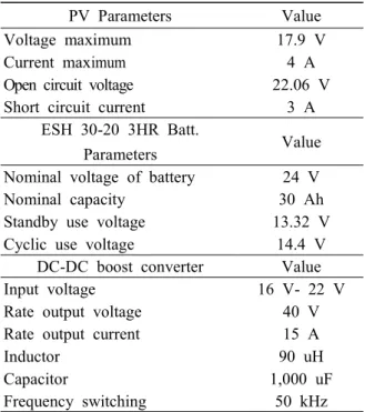
Table 1 Parameters of Proposed Control System PV Parameters Value
Voltage maximum 17.9 V
Current maximum 4 A
Open circuit voltage 22.06 V Short circuit current 3 A
ESH 30-20 3HR Batt.
Parameters Value
Nominal voltage of battery 24 V
Nominal capacity 30 Ah
Standby use voltage 13.32 V Cyclic use voltage 14.4 V
DC-DC boost converter Value Input voltage 16 V- 22 V Rate output voltage 40 V Rate output current 15 A
Inductor 90 uH
Capacitor 1,000 uF
Frequency switching 50 kHz
The simulation equivalent circuit of battery includes a 24 V DC source and variable resistance.
The SOC was measured based on charging characteristic of ESH 30-12 3HR battery with an ideal condition at temperature of 25C. Table 1 shows the parameters of PV panel, battery and DC-DC boost converter.
The simulation used the parameters of proposed control system. The simulation results were illustrated as shown in Fig. 4 and Fig. 5.
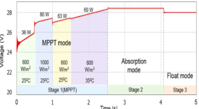
Fig. 4 Battery Voltage During Charging with the Algorithm
Fig. 5 Battery Current During Charging with the Algorithm
In the stage 1 the MPPT control algorithm is operated from 0 to 2.5 s. With various weather conditions, the stage 1 ensures that the battery receives the maximum power from the solar panel. From 2.5 to 4.2 s, the
controller changes to the stage 2. The voltage controller is used to keep the voltage at overvoltage level of battery. From 4.2 to 5 s, the controller changes to the stage 3. In the stage 3, the battery voltage needs to be kept at stand-by used level. These results prove output voltage, current at solar irradiance with different levels of 600 W/m, 1000 W/m, 800 W/m, and the different temperature of 25C, 35C.
The maximum powers are 36 W, 80 W, 63 W, and 60 W, respectively. The system makes sure that the battery charging current always stays under the initial current of the battery and the battery charging voltage below the overvoltage limit. When the battery voltage automatically increases up to overvoltage level, then the controller changes to next stage (absorption stage).
In the absorption stage the SOC is less than 95%, the voltage controller is used to keep the voltage at overvoltage level of the battery.
When the SOC reaches 95%, the float mode is operated. In the float mode, the battery voltage needs to keep the stand-by mode level.
4. Conclusions
A combined control algorithm for the SOC battery and MPPT is proposed in this paper.
The performance enhancement of one DC-DC boost converter for both charging battery and MPPT function has been achieved by replacing the bulk charge stage with MPPT during charging the battery. For that purpose, the SOC determination method is adopted to charge the battery quickly, safely and properly.
The simulation is executed by using PSIM
software. From the simulation result it can be concluded that the proposed control algorithm has a good performance of charging the battery and MPPT. The results obtained in this paper are useful in designing a stand-alone PV system in the rural life like Mongolian nomadic herders.
Acknowledgements
This research was financially supported by the Ministry of Education and National Research Foundation of Korea (NRF) through the Human Resource Training Project for Regional Innovation.(2014H1C1A1066941)
References
[1] National Statistics Office of Mongolian Web Site: http://www.en.nso.mn/
[2] Hong, W. and Donglai, Z., “The Stand-Alone PV Generation System with Parallel Battery Charger,” Electrical and Control Engineering, pp.
4450-4453, 2010.
[3] Mournita, D. and Vivek, A., “A Novel Control Strategy for Stand-Alone Solar PV Systems with Enhanced Battery Life,” Applied Power Electronics Conference and Exposition 2014, pp.
2880-2887, 2014.
[4] Antonio, M.S.S.A., Luciano, S., and Mario, L.,
“PV Battery Charger Based on the Zeta Converter," Industrial Electronics, pp. 379-384, 2015.
[5] Seong, C.C., Min, H.S., Dong, R.K., Chung, Y.W., and Yong, C.J., “Versatile Power Transfer Strategies of PV Battery Hybrid System for Residential Use with Energy Management
System," International Power Electronics Conference ECCE ASIA, pp. 409-414, 2014.
[6] Wen, Y.C., “The State of Charge Estimating Methods for Battery,” International Scholarly Research Network ISRN Applied Mathematics, Vol. 7, No. 5, pp. 5874-5880, 2013.
[7] Xianodong. L and Jiangwen. W., “Modeling and Control of the Distributed Power Converters in a Standalone DC Microgrid,” Multidisciplinary Digital Publishing Institute Journal, pp. 3-19, 2016.
[8] Anwarul, M.H., Swati, Sh., Devedra, N.,
“Maximum Power Point Tracking Algorithm, INC Method for Improved Stability over P&O in Photovoltaic System Operation,” International Journal of Current Engineering and Scientific Research, Vol. 2, pp. 94-102, 2015.
[9] Chang, U.L., Jae, S.K., Tae, Y.S., Dong, H.Ch.,
“MPPT Control of Photovoltaic System Using FLC-PI Controller,” 13th International Conference on Control, Automation and Systems 2013, Vol.
2, pp. 437-439, 2013.
[10] Kotac, V.C., Preti, T., “DC to DC Converter in Maximum Power Point Tracker,” International Journal of Advanced Research in Electrical, Electronics and Instrumentation Engineering, Vol.
2, pp. 6115-6125, 2015.
[11] Suraj, K.P., Mahadik, D.K., “Design of Maximum Power Point Tracking(MPPT) Based PV Charger,” IOSR Journal of Electronics and Communication Engineering, pp. 27-33, 2013.
[12] Shen, Y.T., Cheng, T.T., “Photovoltaic Power System with an Interleaving Boost Converter for Battery Charger Applications,” International Journal of Photoenergy, Vol. 2012, Article ID 936843, pp. 15, 2012.
[13] Jaypalshinh, C., Parin, Ch., Tejas, M., Ashish, J., “Comparison of MPPT Algorithms for DC-DC Converters Based Photovoltaic Systems,”
International Conference on Energy Efficient Technologies for Sustainability, pp. 476-481, 2013.
[14] Li, G., Ye, Z., Cheng, S.W., “A New Battery Energy Storage System Control Method Based on SOC and Variable Filter Time Constant,”
Innovative Smart Grid Technologies, pp.1-7, 2012.
[15] Dong, W.K., Sang, M.L., Soon, G.H., Jong, W.K., “The Impact of Co-creation Implementation on the Performance of Small and Medium Manufacturers," The Journal of Information System (KAIS), Vol. 24, No. 4, pp.
1-19, 2015.
[16] Frina, A., Fleur, F., and Roland, K., ect
“Towards Engineering Clinical Pathways,"
KIECA, Vol. 5, No. 2, pp. 207-224, 2011.
투덴수런 오운자르갈 (Oyunjargal Tuvdensuren)
∙학생회원
∙몽골 과학 기술 대학교 전력공학 과 학사
∙몽골 과학 기술 대학교 전력공학과 석사
∙2015년 3월-현재: 창원대학교 전기공학과 박사과정
∙관심분야 : 전력전자, 신재생 에너지, 정보시스템 성과
레덧탕 (Tat-Thang Le)
∙학생회원
∙Hanoi University of Science and Technology 전기공학과 학사
∙창원대학교 전기공학과 석사
∙현재: 창원대학교 전기공학과 박사과정
∙관심분야 : 전력전자, 신재생 에너지, 초전도 응용
박 민 원 (Min-Won Park)
∙정회원
∙창원대학교 전기공학과 학사
∙일본오사카대학교 전기공학과
석사
∙일본오사카대학교 전기공학과 박사
∙현재: 창원대학교 전기공학과 교수
∙관심분야 : 신재생 전력변화 시스템, 전력전자 시스 템, RTDS/RSCAD
유 인 근 (In-Keun Yu)
∙비회원
∙동국대학교 전기공학과 학사
∙한양대학교 전기공학과 석사
∙한양대학교 전기공학과 박사
∙현재: 창원대학교 전기공학과 교수
∙관심분야 : ESS, 제어 시스템, PSCAD/EMTDC, RTDS/RSCAD, 신재생 에너지