접수일자 : 2011년 12월 02일 심사일자 : 2012년 02월 10일 최종완료 : 2012년 03월 23일
*교신저자, E-mail : [email protected]
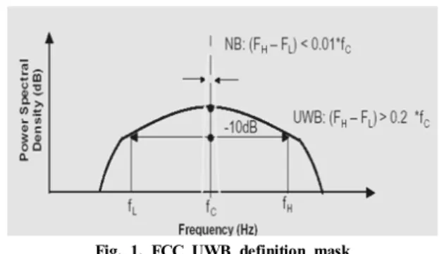
Fig. 1. FCC UWB definition mask
A study of the interference measurement analysis between 3.4125GHz band broadcasting system and
UWB wireless communication system
論 文 11-1-2
송 홍 종* Hong-Jong Song
Abstract
Ultra wideband (UWB) technologies have been developed to exploit a new spectrum resource in substances and to realize ultra-high-speed communication, high precision geo-location, and other applications. The energy of UWB signal is extremely spread from near DC (Direct Current) to a few GHz. This means that the interference between conventional narrowband systems and UWB systems is inevitable. However, the interference effects had not previously been studied from UWB wireless systems to conventional wireless systems sharing the frequency bands such as broadcasting system. This paper experimentally evaluates the interference from two kinds of UWB sources, namely an orthogonal frequency division multiplex UWB source and an impulse radio UWB source, to a broadcasting transmission system. The S/N ratio degradation of broadcasting system is presented. From these experimental results, we show that in all practical cases UWB system can be coexisted 35m distance in-band broadcasting network.
Keywords : UWB, frequency sharing, interference measurement, broadcasting system
I. Introduction
Ultra wide-band (UWB) technology has been an interesting topic in the communication research and development area. UWB service supports for the high data rates, low-power transmissions, low cost, ro- bustness to multi-path fading, and excellent range resolution (geo-location) capabilities. UWB service can be used in the design of wireless local and personal area networks providing advanced integrated multi- media services to nomadic users within personal area [1].
Fig. 1. shows the FCC (Federal Communications Commission) UWB definition mask. UWB signal is generated using sub-nanosecond pulse thus spreading
energy over very large frequency band. A UWB radio signal bandwidth occupies more than 20% of a center frequency or more than 500 MHz. This bandwidth is much greater than the bandwidth used by any cur- rent technology for communication. Due to the very large bandwidth, no spectrum can be allocated to UWB exclusively, thus UWB band overlaps with many other narrowband systems. Therefore, to guarantee existing systems from UWB emissions, the FCC restricted the UWB operating bands in the 3.1-10.6 GHz fre-
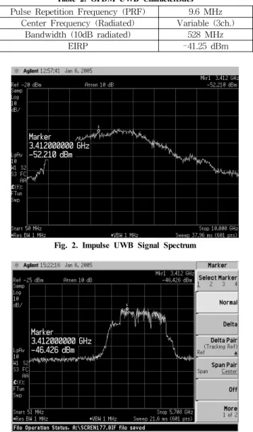
Pulse Repetition Frequency(PRF) 9.6MHz
Center Frequency(Radiated) 4.7GHz
Bandwidth(10dB radiated) 3.2GHz
EIRP -41.5dBm
Table 1. Impulse UWB Characteristics
Pulse Repetition Frequency (PRF) 9.6 MHz Center Frequency (Radiated) Variable (3ch.)
Bandwidth (10dB radiated) 528 MHz
EIRP -41.25 dBm
Table 2. OFDM UWB Characteristics
Fig. 2. Impulse UWB Signal Spectrum
Fig. 3. OFDM UWB Signal Spectrum
Fig. 4. Ch1 off OFDM UWB Signal Spectrum
quency range and regulated UWB power emission by defining frequency-power masks for each specific UWB application/device. As a result, the assessment of interference caused by UWB devices is of funda- mental importance to guarantee not conflicting coex- istence and to gain acceptance of UWB technology worldwide. Some results on the coexistence between UWB and existing fixed wireless systems operating in the 3-5 GHz band have been already presented in the literature and in regulatory forums [2].
The FCC rulings proposed a radiated power limit from UWB devices of –41.25 dBm/MHz from 3.1 to 10.6 GHz [3]. In comparison with the GPS and other indoor communications techniques the effects of wire- less UWB systems on 3.412 GHz broadcasting service have not been well covered in the literature. This is probably not surprising. This on air relay service is not used frequently because of using a broadcasting station for special issue such as sports event, outdoor entertainment, and so on.
Some experiments have been performed. For exam- ple, in [4], the effect of a prototype UWB communica- tion system meeting IEEE requirements on a wireless system was examined.
II. Experiment System Descriptions
A. Victim System
The victim used in this study was a broadcasting relay network which is interfaced between broad- casting center station and broadcasting relay stations. The receiver carrier frequency is 3.4125 GHz. The received signal was connected with a RF cable for measuring the S/N ratio for the UWB inter- ference effect.
B. UWB characteristics
Fig. 5. Proposed Emission Masks
Interference distance
UWB Transmitter
Attenuator (Agilent 8494B/11dB
&
8496B/110dB)
UWB Generator (Time Domain
&
Wisair) Amplifier
(Agilent 83020A)
Controller Relay Station (Transmitter)
Receiver (30dB gain)
Signal to Noise (Tektronix VM700A) Microwave Console
(Ikegami PF701)
Fig. 6. Conceptual diagram of interference measurement set-up
Fig. 7. Measurement set-up of interference between Broadcast relay and UWB
The impulse and OFDM UWB transmitter em- ployed in this experiment use parameter values of Table 1 and Table 2. The impulse UWB spectral characteristic is shown in Fig. 2 which is manufac- tured by The Time Domain Corp. (PulseON200TM).
The OFDM UWB spectral characteristics are shown in Fig. 3 and Fig. 4 which is manufactured by The Wisair Corp. In this measurement set-up, UWB transmitter is almost satisfied with FCC Part 15 emission regulation for practical usage [3].
C. Comparison of Emission Masks of UWB system
Previously, UWB applications such as ground probing radar have operated on a quasi-legal basis.
Their numbers were small and the benefits outweigh the risks. It was only about five years ago when interests within the USA began a serious look at applications for high data rate communications. The main applications foreseen are said to be wireless connections for home audio/video equipment and WLAN, although broadcasting service is not ruled out in the longer term. In Feb. 2003, the FCC re- confirmed the provisional mask (Fig. 5), at -41.25 dBm/MHz mean power density from 3.1-10.6 GHz, for a further period of evaluation. At the same time arguments that 1 dB increase in noise would cause significant interference to mobile phones were dis- missed [5]. This FCC report agrees that capacity would be impacted, but states that operators should incorporate higher margins. It cites that interference from in case of mobile service could legally have spurious levels as high as -13 dBm/MHz, forgetting that industry requirements are much tighter than this.
While the European Commission is to be adopting a similarly proactive stance towards UWB, the radio regulatory body CEPT is adopting a more cautious approach. Studies have indicated that interference to 5GHz WLAN could cover 5m distance causing significant problems in meetings and offices. ETSI is in the process of producing a formal request for spectrum for UWB. ITU will report on UWB studies
next year. By this time, however, major market areas of the world will probably have decided which way to go.
D. S/N ratio Measurement System
This paper presents experimental results of the coexistence test with these two different systems.
The main goal of this work is to determine how the performance of 3.4125 GHz band broadcasting relay service is degraded in the existence of the UWB device in the neighborhood
-70 -65 -60 -55 -50 -45 -40
0 5 10 15 20 25 30 35 40
dB
distance(m)
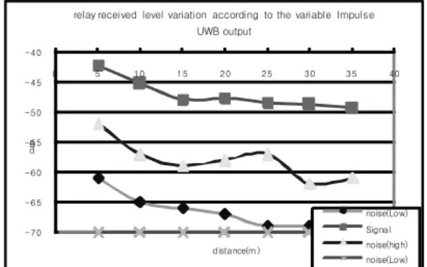
relay received level variation according to the variable Impulse UWB output
noise(Low) Signal noise(high) noise(Low) no-UWB
Fig. 8. Relay received level variation according to the variable Impulse UWB output
Relay received level variation according to the variable Impulse UWB output (Fixed distance : 2m)
-70 -65 -60 -55 -50 -45 -40
0 5 10 15 20 25 30
Attenuation(dB)
dB
cur1(Low) Signal cur2(high) noise(Low) no-UWB
Fig. 9. Relay received level variation according to the variable Impulse UWB output attenuation(Fixed distance: 2m)
Realy received level variation according to the variable OFDM UWB output (ch. 1 off)
-75 -70 -65 -60 -55 -50 -45 -40
0 5 10 15 20 25 30 35 40
distance(m)
dB
cur1(low) signal cur2(high) noise(Low) no-UWB
Fig. 12. Realy received level variation according to the variable OFDM UWB output(ch1 off)
Realy received level variation according to the variable OFDM UWB output
-70 -65 -60 -55 -50 -45 -40 -35 -30
0 5 10 15 20 25 30 35 40
distance(m)
dB
cur1(Low) Signal cur2(high) noise(Low) no-UWB
Fig. 10. Relay received level variation according to the variable OFDM UWB output
Relay received level variation according to the variable OFDM UWB output (Fixed distance : 2m)
-70 -60 -50 -40 -30 -20
0 5 10 15 20 25 30 35 40
Attenuation( dB)
dB
cur1(Low) Signal cur2(high) noise(Low) no-UWB
Fig. 11. Relay received level variation according to the variable OFDM UWB output(Fixed distance: 2m)
Relay received level variation according to the variable OFDM UWB output
(Fixed distance : 2m, ch. 1 off)
-70 -65 -60 -55 -50 -45 -40
0 5 10 15 20 25 30 35 40
Attenuation(dB)
dB
cur1(low) signal cur2(high) noise(Low) no-UWB
Fig. 13. Relay received level variation according to the variable OFDM UWB output(Fixed distance: 2m, ch1 off)
The measurement configuration employed in this experiment is described in Fig. 6. The receiving an- tenna received direct signal from the relay station that was 3.4125 GHz. An interface microwave con- sole (Ikegami PF701) and signal analyzer (Tektronix VM700A) for the S/N ratio check are used. The output signal of the UWB signal generator is an interface amplifier (Agilent 83020A) and attenuator (Agilent 8494B/8496B) for generating the precision output UWB power where UWB signal generator is controlled by the Notebook PC. This setup enabled us to eliminate the effects of signal fading which is not the subject of this study. Transmission via space or power lines was completely negligible.
III. Experimental Results and Analysis
According to this experiment result, it is -49.3 dB which is the received level from the relay station.
First, in case of the relay received level variation according to the variable impulse UWB output. (Fig.
8.), we find that the impulse UWB system has not interference effects more than 35m distance to the broadcasting relay service.
Second, in case of the relay received level variation according to the variable impulse UWB output at- tenuation (see Fig. 9), we find that the impulse UWB system has not interference effects more than 20 dB power attenuation at the 2m fixed distance to the broadcasting relay service
Third, in case of the relay received level variation according to the variable OFDM UWB output (Fig.
10), we find that the OFDM UWB system has not interference effects more than 30m distance to the broadcasting relay service.
Fourth, in case of the relay received level variation according to the variable OFDM UWB output at- tenuation, (Fig. 11), we find that the OFDM UWB system has not interference effects more than about 27 dB power attenuation at 2m fixed distance to the broadcasting relay service.
Fifth, in case of the relay received level variation according to the variable OFDM UWB output (ch.
1 off) (Fig. 12), we find that the OFDM UWB system has not interference effects more than 15m distance to the broadcasting relay service.
Sixth, in case of the relay received level variation according to the variable OFDM UWB output (at fixed distance 2m and ch. 1 off) (Fig. 13), we find that the OFDM UWB system has not interference effects more than 20 dB power attenuation at the 2m fixed distance to the broadcasting relay service.
V. Conclusion
In this paper, we study the coexistence issues between an UWB-based communication system and
a broadcasting relay system.
The relay received level is variable according to the distance variation. We know that the impulse and OFDM UWB system has not interference effect more than 35m and 30m distance to the broadcasting relay service.
In case of the relay received level variation accord- ing to the variable attenuation, we find that the im- pulse and OFDM UWB system has not interference effect more than 20dB and 27dB attenuation to the broadcasting relay service at fixed distance of 2m.
In case of the relay received level variation accord- ing to the channel 1 off, where channel 1 center frequency is 3.39 GHz, we find that the system has not interference effect more than 15m distance and more than 20dB power attenuation at 2m distance to the broadcasting relay service.
Due to the very large UWB signal bandwidth, the assessment guarantees acceptance of UWB technology worldwide.
[ 참 고 문 헌 ]
[1] R. Giuliano, F. Mazzenga, and F. Vatalaro, "On the interference between UMTS and UWB systems,"
Proceedings of the IEEE Conference on Ultra Wideband Systems and Technologies, pp. 339-343, Nov. 2003.
[2] J. R. Hoffman, M. G. Cotton, R. J. Achatz, and R.
N. Statz, "Addendum to NTIA Report 01-384:
Measurements to Determine Potential Interference to GPS Receivers from Ultrawideband Transmission Systems," NTIA Report 01-389, Sept. 2001.
[3] FCC 02-48 First Report and Order(R&O), Revision of Part 15 of the Commission’s Rules Regarding Ultra-Wideband Transmission Systems : FCC, Feb.
2002.
[4] Intel, General-Atomics "C-band satellite interference measurements at TDK RF test range," IEEE 802.15 WG for Wireless Personal Area Networks, Jan.2004.
[5] FCC 03-33 Memorandum, Opinion and Order, FCC, Feb. 2003
Biography
송 홍 종
1992년 2월 : 전남대학교 물리학과 (이학사)
1994년 2월 : 전남대학교 전자공학과 (공학석사)
1994년 1월 ~ 1998년 3월 : 현대전자 정보통 신연구소 2006년 9월: 연세대학교 전기×전자 공학과 박사수료 2011년 8월 : 서울과학기술대학교 NID융합기술대학원 (공학박사)
2000년 11월 ~ 현재 : 방송통신위원회 국립전파연구원 재직 중
<주 관심분야>
방송통신융합형 신기술, 광대역정보통신망 , UWB기술, 광대역무선통신시스템, 광대역 무선안테나기술 등