CT-Based Essential Cardiac Anatomy for Radiology
Residents to Understand Congenital Heart Disease
전공의의 선천성심장병 이해를 위한 CT 영상에서의 필수 심장해부학
Hyun Woo Goo, MD*
Department of Radiology, Asan Medical Center, University of Ulsan College of Medicine, Seoul, Korea
Congenital heart disease is often associated with severe clinical presentations demanding prompt imaging diagnosis and appropriate treatment. Therefore, radiologists, particularly radi- ology residents, should be familiar with essential cardiac anatomy in order to diagnose congeni- tal heart disease. In our clinical practice, cardiac anatomy is commonly depicted on CT images acquired with state-of-the art CT imaging techniques; however, the related imaging findings may be overlooked due to lack of attention, experience, or knowledge. It is partly due to the fact that CT-based illustration of cardiac anatomy to help understand congenital heart disease is cur- rently scarce. In this article, cardiac imaging planes; crucial anatomical landmarks; morphologi- cal features of cardiac chambers, septa, and valves; and connections of cardiac segments are il- lustrated using cardiac CT images to facilitate understanding of congenital heart disease.
Index terms Anatomy; Heart Defects, Congenital; Multidetector Computed Tomography
서론
흔한 선천성기형 중 하나인 선천성심장병은 발전된 관련 수술 및 시술법과 중환자실 치료 로 인해 많은 수의 환자가 성인 나이까지 생존하게 되었다. 실제 보고된 자료에 따르면 한국 성인의 선천성심장병 유병률은 2006년 인구 10000명 당 35.8명에서 2015년 65.6명으로 두 배 가까이 증가하였다(1). 따라서 심장이 포함된 성인 전산화단층촬영 영상판독 시 심장해부 학에 대한 필요성이 강조되고 있다(2, 3). 또한 최근 발전된 영상기법으로 촬영된 심장 전산 화단층촬영은 소아 선천성심장병 환자에서 심장 외 혈관, 기도, 그리고 폐뿐만 아니라, 심장
Received January 2, 2019 Revised March 17, 2019 Accepted March 20, 2019
*Corresponding author Hyun Woo Goo, MD Department of Radiology, Asan Medical Center, University of Ulsan College of Medicine,
88 Olympic-ro 43-gil, Songpa-gu, Seoul 05505, Korea.
Tel 82-2-3010-4388 Fax 82-2-476-0090 E-mail ghw68@hanmail.net This is an Open Access article distributed under the terms of the Creative Commons Attribu- tion Non-Commercial License (https://creativecommons.org/
licenses/by-nc/4.0) which permits unrestricted non-commercial use, distribution, and reproduc- tion in any medium, provided the original work is properly cited.
ORCID iD Hyun Woo Goo https://
orcid.org/0000-0001-6861-5958 Recipients of Silver Award for Best Scientific Exhibition Awards at 2018 KCR Annual Meeting.
Invited for the Pictorial Essay.
내 구조물과 관상동맥의 형태학적 평가에 있어 그 우수함이 증명되어 그 사용이 증가하고 있다(4- 14). 따라서 특히 경험이 적은 영상의학과 전공의의 선천성심장병 이해를 돕기 위한 심장해부학 교육자료가 필요한 시점이다. 심장 전산화단층촬영 영상에서 심장 구조물이 잘 보이는 점을 이용 하면 전통적인 해부학을 대신하여 심장해부학을 이해하는 데 유용하게 사용될 수 있겠다(15). 이를 위해 본 논문에서는 심장 영상면, 심장 전산화단층촬영에 사용되는 시각화 기법, 기본적인 해부학 적 기준점, 심방, 심실, 심중격, 심판막의 형태학적 특징, 그리고 심장분절 간의 연결을 심장 전산 화단층촬영 영상을 이용하여 설명하고자 하였다.
정찰 영상에서의 심장 실루엣
전산화단층촬영 검사의 스캔범위를 결정하기 위해 전후 및 측면투영 정찰 영상을 사용한다. 영 상의학과 의사는 방사선사가 스캔범위 내에 검사영역이 빠짐없이 포함되면서도 과다한 스캔범위 로 불필요하게 환자의 방사선피폭량이 증가하지 않도록 교육 및 감독의 책임이 있다. 따라서 영상 의학과 의사는 정찰 영상에서의 심장 실루엣을 구성하는 심혈관 구조물과 3차원상 위치 관계를 숙 지할 필요가 있다(Fig. 1).
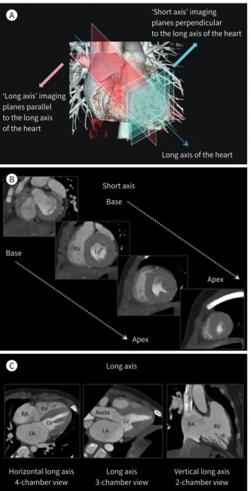
심장 영상면
심장은 흉곽 중격동 내에서 좌측으로 비스듬히 위치하고 있기 때문에, 2차원 영상판독에 일반적 으로 사용되는 축상(axial), 관상(coronal), 시상(sagittal) 영상면 대신에 심장 장축에 평행한 장축 영상과 심장 장축에 직각인 단축 영상이 사용된다(Fig. 2). 여기서 심장의 장축은 심장 기저부의 중 심에서 심첨부를 통화하는 선으로 정의된다. 장축 영상에는 4-chamber 뷰라고 흔히 불리는 수평 장축 영상과 좌측 심장이나 우측 심장을 한눈에 보기 용이한 수직 장축 영상이 포함된다(Fig. 2). 좌 측 심장에 대한 수직 장축 영상들 중에 좌심방, 승모판, 좌심실이 보이는 영상을 2-chamber 뷰와 좌심방, 좌심실, 승모판, 대동맥판이 보이는 영상을 3-chamber 뷰라고 한다.
단축 및 장축 영상 외에 심장해부학에서 유용한 심장 영상면으로 base of ventricles이 있다 (Fig. 3). 양측 심방을 제거한 후 양측 심실을 후상측에서 바라본 영상면으로 심판막 사이의 위치 관 계를 이해하는 데 유용하다(15). 즉, 대동맥판막과 승모판은 섬유성 연속(fibrous continuity)의 관 계인 반면, 폐동맥판막과 삼첨판 사이는 우심실 유출로를 구성하는 심근에 의해 떨어져 위치한다.
유용한 시각화 기법
심장 전산화단층촬영은 영상판독을 위해 2차원 다평면재구성(multiplanar reformation)과 최 대강도투시(maximum intensity projection) 뿐만 아니라 다양한 3차원 시간화 기법을 사용한다.
일반적인 볼륨 렌더링 기법 이외에도 색깔로 분류된(color-coded) 여러 개의 3차원 영상을 합병하
여 나타내는 합병(merged) 볼륨 렌더링 기법은 특히 혈관에 의한 외인성 기도압박을 나타내거나
다발성주요대동맥기시폐측부동맥(multiple major aortopulmonary collateral arteries; MAPCAs) 지도를 만드는데 유용하게 사용된다(8, 9). 또한 조영증강된 심장 내강을 시각화하는 일반적인 볼 륨 렌더링 기법을 수정하여 내강을 투명하게 하는 투명-내강(transparent-lumen) 볼륨 렌더링 기 법을 사용하면 심장 내 구조물이 사실적으로 보여 매우 유용하다(Fig. 4). 최근에는 심장 전산화단 층촬영 데이터를 사용하여 새로운 사실적 3차원 영상 렌더링 기법인 시네마틱(cinematic) 렌더링 기법의 임상적 가치를 탐색하고 있다(Fig. 5) (16). 시네마틱 렌더링에서는 일반적인 볼륨 렌더링과
Fig. 1. Cardiovascular structures forming a cardiac silhouette on CT scout images.A. On anteroposterior CT scout image, the right cardiac silhouette is formed by the superior vena cava (1) and right atrium (2), and the left cardiac silhouette is formed by the aortic knob (3), pulmonary conus (4), left atrial appendage (5), and LV (6).
B. These cardiovascular structures (1–6) forming the right and left cardiac silhouettes are shown on the frontal volume-rendered CT image.
C. On lateral CT scout image, the anterior and posterior cardiac silhouettes (dotted lines) are shown.
D. Sagittal volume-rendered CT image shows that the anterior cardiac silhouette is formed by the RV and the posterior cardiac silhouette is formed by the LA and LV. The MPA arising from the RV is noted.
LA = left atrium, LV = left ventricle, MPA = main pulmonary artery, RV = right ventricle A
C D
B
는 달리 보다 복잡하고 전체적인 조명 모델을 사용하고 그림자 효과를 포함하여 사실적인 3차원 영상을 만들어 낸다. 비록 3차원 영상은 아니지만, 3차원 프린팅을 이용한 심장모델을 이용하여 눈 으로 보고 손으로 확인하며 심장해부학을 익힐 수도 있다. 그러나 3차원 프린팅 심장모델은 소스가 되는 3차원 영상에 비해 사실 충실도가 떨어질 수 밖에 없으며, 3차원 프린팅 전에 시행하는 영상분 할의 질에 따라 생산된 심장모델의 사실 충실도에 큰 차이가 있을 수 있다는 점을 알아야 한다.
심장해부학의 기준
심장의 해부학적 구조물 중 선천성심장병을 이해하는 데 도움이 되는 해부학적 기준점인 ‘심첨
‘Short axis’ imaging planes perpendicular to the long axis of the heart
‘Long axis’ imaging planes parallel to the long axis of the heart
Long axis of the heart Short axis
Long axis
Horizontal long axis 4-chamber view
Long axis 3-chamber view
Vertical long axis 2-chamber view Base
Base
Apex
Apex A
B
C
Fig. 2. Cardiac CT imaging planes.
A. Frontal volume-rendered CT image showing the long axis of the heart. The long axis imaging planes (pink color) are parallel to that of the heart, while the short-axis imaging planes (blue col- or) are perpendicular to the long axis of the heart.
B. A series of short-axis CT images from the base of the RV and LV to the cardiac apex.
C. Horizontal and vertical long-axis images showing 4-, 3-, and 2-cham- ber views.
LA = left atrium, LV = left ventricle, RA = right atrium, RV = right ventricle
부’와 ‘crux cordis’에 대해 정의와 임상적 의의에 대해 알아보자.
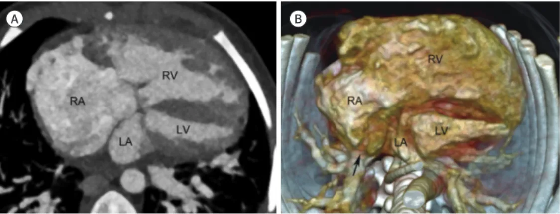
심첨부는 심장의 뾰족한 끝으로 정상적으로 좌심실에 의해 형성된다(Fig. 2C). 반면에 심첨부가 좌심실 대신 우심실에 의해 형성되는 경우에는 좌심실 형성부전을 시사하는 영상소견이다(Fig. 6).
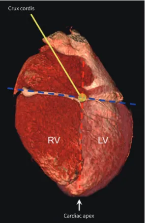
Crux cordis는 방실고랑(atrioventricular sulcus)과 후방 심실사이고랑 및 후방 심방사이교랑 이 십자로 교차하는 부위로(Fig. 7), 심한 형성부전을 보이는 심실이 crux cordis와 연해 있으면 ‘형 태학적’ 좌심실로 볼 수 있다는 임상적 의의가 있다.
Transparent-lumen VR
Voxel number
Opacity
Air Water Soft Contrast Bone HU
tissue
Conventional VR
Fig. 4. Comparison between conven- tional VR and transparent-lumen VR techniques. In conventional VR, a trap- ezoidal opacity curve is located around the attenuation values of contrast- enhanced blood. In contrast, a trape- zoidal opacity curve moves to the at- tenuation values of water and soft tissue in transparent-lumen VR.
VR = volume rendering
Fig. 3. Base of ventricles. Posterior and superior volume-rendered CT im- ages of both ventricles showing the spatial relationships between the left and right semilunar and atrioventricu- lar valves. In contrast to the fibrous continuity between the AV and MV, a muscular right ventricular outflow tract is present between the PV and TV.
AV = aortic valve, MV = mitral valve, PV = pulmonary valve, TV = tricuspid valve
A B
D C
Fig. 5. Comparison between conventional volume rendering and cinematic rendering techniques in a pa- tient who underwent arterial switch operation for transposition of the great arteries.
A-D. Compared with conventional volume-rendered cardiac CT images (A, B), cinematic rendering creates photorealistic images (C, D) by using a more complex lighting model. However, obscuration of some cardio- vascular structures due to shadowing effects is a potential pitfall of cinematic rendering. The PT is anterior to the AA as a consequence of the LeCompte maneuver. The transferred right and left coronary arteries ap- pear patent without significant stenosis.
AA = ascending aorta, LV = left ventricle, PT = pulmonary trunk, RA = right atrium, RV = right ventricle
Fig. 6. Cardiac apex formed by the RV in a patient with double outlet RV and a small LV.
A, B. Four-chamber cardiac CT image (A) and inferior volume-rendered cardiac CT image (B) show an en- largement of the RA and RV. In contrast, the LA and LV appear relatively small. A partial anomalous pulmo- nary venous connection (arrow), in which the right pulmonary vein is anomalously connected to the RA, is also noted.
LA = left atrium, LV = left ventricle, RA = right atrium, RV = right ventricle
A B
심장분절의 형태학적 특징
심장분절의 명칭은 우리 몸에서의 위치가 아니라 각 분절의 형태학적인 특징에 의해 결정된다.
따라서 복잡한 선천성심장병에서 심장분절의 명칭을 정하는 데 사용되는 중요한 개념이다.
심방의 형태학적 특징
우심방과 좌심방을 구분하는데 사용되는 형태학적 특징이 Table 1에 정리되어 있다. 이중 가장 정확하게 구분할 수 있는 형태학적 특징은 심방귀(atrial appendage) 내 빗살근(pectinate mus- cles)의 범위이다(Fig. 8). 형태학적 우심방에는 sinus venosus와 primitive 우심방 사이를 가르는 terminal 고랑 또는 능(crest), 타원오목(oval fossa)이 있고, 관상 정맥동(coronary sinus)이 연결 되어 있다(Fig. 8) (17). 태아순환의 하나인 타원공(oval foramen)은 신생아에서 흔히 열려 있다가 우심방 압력이 감소하면서 점차적으로 닫히게 된다. 그러나 이후에도 약 25%에서 완전히 닫히지
Crux cordis
Cardiac apex Fig. 7. Crux cordis. Inferior volume-rendered cardi-
ac CT image shows crux cordis where the atrioven- tricular sulcus (blue dotted line) and the conjunc- tion (red dotted line) of the posterior interventricular sulcus and posterior interatrial sulcus cross each other. The cardiac apex (arrow) formed normally by the LV is also indicated.
LV = left ventricle, RV = right ventricle
Table 1. Morphological Features of Right Atrium and Left Atrium
Right Atrium Left Atrium
Appendage shape Triangular shape with broad junction Finger-like shape with narrow junction
Terminal crest or sulcus Yes No
Oval fossa Yes No
Extent of pectinate muscles Extending to atrioventricular junction
Not extending to atrioventricular junction
않아 난원공개존증(patent foramen ovale)으로 남아있게 된다. 형태학적 좌심방은 이와 같은 구 조물이 없고 폐정맥과 연결되어 있다.
심실의 형태학적 특징
우심실과 좌심실을 구분하는데 사용되는 형태학적 특징이 Table 2에 정리되어 있다. 우심실의 형 태학적 특징 중 하나인 moderator band는 심실중격과 전유두근(anterior papillary muscle) 기 저부위 사이를 가로지르는 심근 밴드이다(Fig. 9). 우심실중격에 작은 내유두근(medial papillary muscle)이 보일 수 있는데, 만약 이 내유두근이 심실중격결손의 가장자리에 위치하는 것이 확인 되면 가장 흔한 peri-membranous 심실중격결손으로 볼 수 있는 해부학적 기준점 중의 하나로 도
Fig. 8. Morphological features of the RA.A. Transparent volume-rendered cardiac CT image showing the pectinate muscles in both atria. The pecti- nate muscles in the dilated right atrial appendage extend to the right atrioventricular junction (asterisks), while those in the left atrial appendage do not extend to the left atrioventricular junction (arrows).
B. Axial cardiac CT image showing the terminal sulcus (arrow) in a patient with Kawasaki disease and a right coronary artery aneurysm (asterisk).
C. Transparent volume-rendered cardiac CT image showing the FO, an oval-shaped depression, in the septal surface of the RA. The septal surface of the RV is also seen.
D. Short-axis cardiac CT image showing the coronary sinus (asterisks) draining into the RA.
FO = fossa ovalis, LA = left atrium, RA = right atrium, RV = right ventricle A
C D
B
움이 될 수 있다(Fig. 9) (17). 비록 해부학적으로 경계를 나누는 명확한 기준은 없지만, 심실은 방 실판과 긴장장치(tension apparatus)를 포함하는 입구(inlet), 반월판을 지지하는 출구(outlet), 그 리고 입구와 출구 사이에서 심첨부를 포함하는 잔기둥(trabecular) 부위의 세 부분으로 나뉜다. 우 심실 유출로에는 폐동맥판과 삼첨판 사이에 근육성 능선(ridge)이 있어 crista supraventricularis 라고 불리는데, 이 부위는 해부학적으로 심실누두간주름(ventriculoinfundibular fold), 출구 중
Table 2. Morphological Features of Right Ventricle and Left VentricleRight Ventricle Left Ventricle
Trabeculations Heavy and irregular Fine and regular
Moderator band Yes No
Septal attachment of atrioventricular valve More apical More cranial Fig. 9. Morphological features of the RV.
A. Axial cardiac CT image showing the moderator band (arrows), a muscular band between the apical por- tion of the septomarginal trabecula and free wall of the RV around the base of the anterior papillary muscle.
B. Transparent volume-rendered cardiac CT image showing the MPM (arrow) on the septal surface of the RV.
C. Oblique coronal cardiac CT images demonstrate the inlet, trabecular, and outlet components of the RV.
The VIF (dotted line) forms the superior septal margin of the supraventricular crest. The MPM (arrow) and PV (arrows) are noted.
IVC = inferior vena cava, LA = left atrium, LV = left ventricle, MPM = medial papillary muscle, OS = outlet sep- tum, PV = pulmonary valve, RA = right atrium, RV = right ventricle, RVOT = right ventricular outflow tract, SVC = superior vena cava, VIF = ventriculo-infundibular fold
A
C
B
격, 그리고 중격변연기중(trabecula septomarginalis)의 전 사지(limb)로 구성된다(Fig. 9) (17, 18).
좌심실에는 전외측(anterolateral)과 후내측(posteromedial)의 두 개의 유두근이 있다(Fig. 10).
우심실에는 전(anterior), 후(posterior), 중격(septal) 유두근으로 세 개가 있다.
심중격의 형태학적 특징
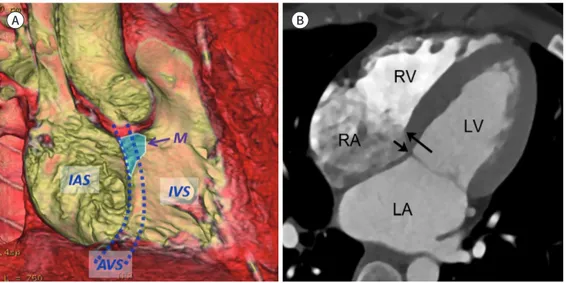
심중격은 크게 심방간(interatrial) 중격, 방실 중격, 그리고 심실간(interventricular) 중격으로 나뉜다(Fig. 11). 이중 방실 중격은 정상적으로 삼첨판의 중격부착부위가 승모판의 중격부착부위 에 비해 약간 심첨부에 위치하기 때문에(< 8 mm/m
2of body surface area) 발생한다. 따라서 방실 중격은 좌심실과 우심방 사이에 위치하는데, 여기에 작은 결손이라도 있으면 좌심실과 우심방 사 이의 큰 압력차이로 인해 자연적으로 막힐 가능성이 매우 낮으므로 수술적 치료의 적응증이 된다.
근육성 심중격과는 달리 대동맥판막 아래에 위치하는 심중격의 작은 부위는 얇은 섬유성 막으로 구성되어 있는 막성(membranous) 부위로 심실중격결손의 약 70%가 이 막성 부위에서 발생한 다(Fig. 11) (19).
심판막의 형태학적 특징
심판막에는 반월판(semilunar valve)에 해당하는 대동맥판막과 폐동맥판막과 방실판에 해당하 는 승모판과 삼첨판이 있다(19). 대혈관과 심실 사이에 위치하는 반월판은 정상적으로 세 개의 판막 첨판(cusp)과 판막엽(leaflet)으로 구성되어 있고, 방실판 중 승모판은 전엽과 후엽 두 개의 판막엽
Fig. 10. Morphological features of the LV. Transparent volume-rendered cardiac CT image shows the ‘A’ and
‘P’ papillary muscles of the LV.
A = anterolateral, LV = left ventricle, P = posteromedial
으로 구성되어 있고, 삼첨판은 전엽, 중격엽, 후엽 세 개의 판막엽으로 구성되어 있다(Fig. 12). 반월 판의 명칭은 대혈관에 의해 결정되고, 방실판의 명칭은 형태학적 심실에 의해 결정된다. 대혈관 사 이의 위치 관계가 선천성심장병 이해와 분류에 중요하며 정상적으로 폐동맥이 대동맥의 앞쪽 좌측
Fig. 11. Septum of the heart.A. Transparent volume-rendered cardiac CT image shows the cardiac septum viewed from the right heart, consisting of the IAS, AVS, and IVS. The AVS is produced by a septal offset between the tricuspid and mitral valves (two dotted lines). The ‘M’ of the cardiac septum is located beneath the aortic valve between the right and non-coronary aortic cusps.
B. The AVS is illustrated on 4-chamber view. Notably, the septal attachment of the tricuspid valve (long ar- row) is apically located, compared with that of the mitral valve (short arrow). The septal offset corresponds to the location of the AVS.
AVS = atrioventricular septum, IAS = interatrial septum, IVS = interventricular septum, LA = left atrium, LV = left ventricle, M = membranous portion, RA = right atrium, RV = right ventricle
A B
Fig. 12. Cardiac valves.
A. Transparent volume-rendered cardiac CT image shows the L, R, and N aortic cusps as well as closed leaflets of the AV. The left main coro- nary artery (arrow) is noted.
B. Transparent volume-rendered cardiac CT image shows closed A and P mitral leaflets. The AV is also seen.
C. Oblique axial cardiac CT image shows the normal spatial relationship between the great arteries, in which the pulmonary artery is located anterior and left to the ascending aorta. In addition, the commissures (arrows) of the two F of the semilunar valves are generally aligned to each other.
A = anterior, AV = aortic valve, F = facing sinuses, L = left, LA = left atrium, LVOT = left ventricular outflow tract, N = non-coronary, P = posterior, PT = pulmonary trunk, R = right, RA = right atrium
A B C
에 위치한다(Fig. 12). 정상과는 달리 대동맥이 폐동맥의 앞쪽에 위치하는 경우에 대혈관 위치이상 이라고 정의하며 대혈관전위와 같은 선천성심장병에서 볼 수 있다.
심장분절 간의 연결
심장분절은 혈류 방향에 따라 정맥과 연결되는 심방, 심방과 연결되는 심실, 그리고 심실과 연결 되는 대혈관으로 구성된다. 정상적으로 폐순환에서는 상, 하대정맥이 형태학적 우심방에 연결되 고, 형태학적 우심방이 형태학적 우심실로 연결되며, 그리고 다음으로 형태학적 우심실이 폐동맥 으로 연결된다(Fig. 13). 한편 체순환에서는 폐정맥이 형태학적 좌심방에 연결되고, 형태학적 좌심 방이 형태학적 좌심실에 연결되며, 마지막으로 형태학적 좌심실이 대동맥으로 연결된다(Fig. 13).
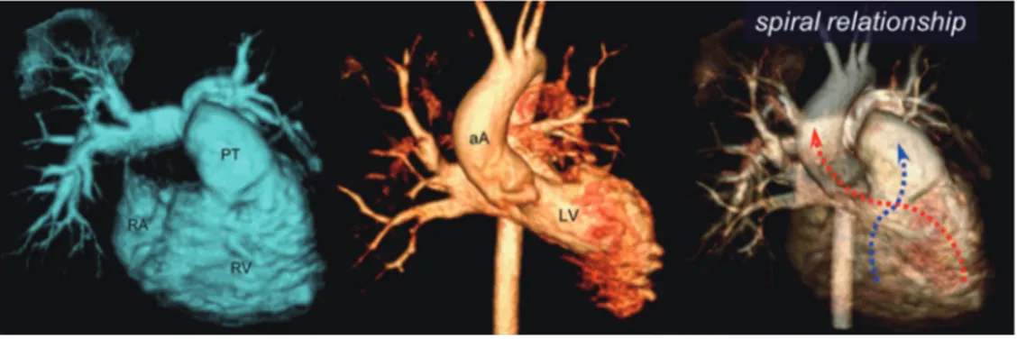
일부 선천성심장병에서 심장분절 간의 연결이 정상적이지 않은 경우가 있다. 심방과 심실은 좌우 평행한 위치관계를 보이는 반면, 대동맥과 폐동맥은 정상적으로 서로 나선형 위치 관계를 보인다 (Fig. 13). 대혈관전위와 같은 선천성심장병에서는 대혈관의 정상적인 나선형 위치 관계를 볼 수 없 고, 대신 특징적으로 상호 평행한 위치 관계를 보인다.
결론
이전에 비해 심장구조물이 영상판독에 잘 보이게 되어 심장해부학에 대한 관심이 요구되는 시점 이다. 다소 어렵게 느껴지는 선천성심장병의 형태학적 이해 증진을 위해 이 논문에서 다룬 심장 전 산화단층촬영 영상을 이용한 심장해부학이 영상의학과 전공의를 비롯하여 상대적으로 경험이 적 은 전임의 선생님들의 심장구조물에 대한 영상판독에 도움을 줄 것으로 믿는다.
Conflicts of Interest
The author has no potential conflicts of interest to disclose.
Fig. 13. Connections of cardiac segments.
In pulmonary circulation (left image), the RA is connected to the RV and then to the PT. In systemic circulation (middle image), the left atrium is connected to the LV and then to the aA. A characteristic spiral relationship is observed between the right and left ventriculoarterial junctions (blue and red dotted arrows).
aA = ascending aorta, LV = left ventricle, PT = pulmonary trunk, RA = right atrium, RV = right ventricle
REFERENCES
1. Jang SY, Seo SR, Moon JR, Cho EJ, Kim E, Chang SA, et al. Prevalence and mortality of congenital heart dis- ease in Korean adults. Medicine (Baltimore) 2018;97:e11348
2. Suranyi P, Varga-Szemes A, Hlavacek AM. An overview of cardiac computed tomography in adults with con- genital heart disease. J Thorac Imaging 2017;32:258-273
3. De Cecco CN, Muscogiuri G, Madrid Pérez JM, Eid M, Suranyi P, Lesslie VW, et al. Pictorial review of surgical anatomy in adult congenital heart disease. J Thorac Imaging 2017;32:217-232
4. Goo HW, Park IS, Ko JK, Kim YH, Seo DM, Yun TJ, et al. CT of congenital heart disease: normal anatomy and typical pathologic conditions. Radiographics 2003;23 Spec No:S147-S165
5. Goo HW, Park IS, Ko JK, Kim YH, Seo DM, Park JJ. Computed tomography for the diagnosis of congenital heart disease in pediatric and adult patients. Int J Cardiovasc Imaging 2005;21:347-365; discussion 367 6. Goo HW. State-of-the-art CT imaging techniques for congenital heart disease. Korean J Radiol 2010;11:4-18 7. Goo HW, Yang DH. Coronary artery visibility in free-breathing young children with congenital heart disease on
cardiac 64-slice CT: dual-source ECG-triggered sequential scan vs. single-source non-ECG-synchronized spiral scan. Pediatr Radiol 2010;40:1670-1680
8. Goo HW. Cardiac MDCT in children: CT technology overview and interpretation. Radiol Clin North Am 2011;
49:997-1010
9. Goo HW. Current trends in cardiac CT in children. Acta Radiol 2013;54:1055-1062
10. Tsai IC, Goo HW. Cardiac CT and MRI for congenital heart disease in Asian countries: recent trends in publica- tion based on a scientific database. Int J Cardiovasc Imaging 2013;29 Suppl 1:1-5
11. Bang JH, Park JJ, Goo HW. Evaluation of commissural malalignment of aortic-pulmonary sinus using cardiac CT for arterial switch operation: comparison with transthoracic echocardiography. Pediatr Radiol 2017;47:
556-564
12. Goo HW, Park SH. Pulmonary vascular volume ratio measured by cardiac computed tomography in children and young adults with congenital heart disease: comparison with lung perfusion scintigraphy. Pediatr Radiol 2017;47:1580-1587
13. Goo HW. Identification of coronary artery anatomy on dual-source cardiac computed tomography before arterial switch operation in newborns and young infants: comparison with transthoracic echocardiography.
Pediatr Radiol 2018;48:176-185
14. Goo HW. Coronary artery anomalies on preoperative cardiac CT in children with tetralogy of Fallot or Fallot type of double outlet right ventricle: comparison with surgical findings. Int J Cardiovasc Imaging 2018;
34:1997-2009
15. Goo HW. CT in pediatric heart disease. In Saremi F, Achenbach S, Arbustini E, Narula J, eds. Revisiting cardiac anatomy: a computed-tomography-based atlas and reference. Boston: Wiley-Blackwell 2011:76-84 16. Rowe SP, Johnson PT, Fishman EK. Cinematic rendering of cardiac CT volumetric data: principles and initial
observations. J Cardiovasc Comput Tomogr 2018;12:56-59
17. Mori S, Fukuzawa K, Takaya T, Takamine S, Ito T, Fujiwara S, et al. Clinical cardiac structural anatomy recon- structed within the cardiac contour using multidetector-row computed tomography: atrial septum and ventricular septum. Clin Anat 2016;29:342-352
18. Saremi F, Ho SY, Cabrera JA, Sánchez-Quintana D. Right ventricular outflow tract imaging with CT and MRI:
part 1, morphology. AJR Am J Roentgenol 2013;200:W39-W50
19. Mori S, Fukuzawa K, Takaya T, Takamine S, Ito T, Fujiwara S, et al. Clinical cardiac structural anatomy recon- structed within the cardiac contour using multidetector-row computed tomography: the arrangement and location of the cardiac valves. Clin Anat 2016;29:364-370
전공의의 선천성심장병 이해를 위한 CT 영상에서의 필수 심장해부학
구 현 우*
선천성심장병은 흔히 심한 임상증상을 나타내어 신속한 영상진단과 적절한 치료를 요한다.
따라서 영상의학과의사, 특히 전공의는 선천성심장병의 진단을 위해 필수 심장해부학을 알고 있어야 한다. 최근 발전된 전산화단층촬영 기법으로 영상판독 시 심장구조물을 흔히 볼 수 있게 되었지만, 관련된 영상소견은 주의집중, 경험, 또는 지식의 부족으로 그냥 지나치는 경우가 있 다. 이는 부분적으로 현재 선천성심장병 이해를 돕기 위해 제작된 전산화단층촬영 영상-기반 교육자료가 많지 않은 것에 기인한다. 따라서, 이 임상화보에서는 심장 전산화단층촬영 영상을 이용하여 심장 영상면, 기본적인 해부학적 기준점, 심실, 심방, 심중격, 심판막의 형태학적 특 징, 그리고 심장분절 간의 연결을 설명함으로써 선천성심장병에 대한 이해를 돕고자 한다.
울산대학교 의과대학 서울아산병원 영상의학과