https://doi.org/10.5050/KSNVE.2019.29.1.030 ISSN 1598-2785(Print), ISSN 2287-5476(Online)
1)
Nomenclature
C : Speed of wave propagation
J, K : Bessel functions of the first kind V
0: Applied voltage
a, b : Inner and outer radii of the discs
† Corresponding Author ; Fellow Member, Soongsil University E-mail : [email protected]
* Member, Soongsil University
‡ Recommended by Editor Gi-Woo Kim
© The Korean Society for Noise and Vibration Engineering
Vibration Analysis for an Ultrasonic Transducer Coupled with Interior and Exterior Piezoelectric Discs
내부 및 외부 압전 원판이 결합된 초음파 트랜스듀서의 진동 해석
Chunguang Piao * and Jin Oh Kim †
박 춘 광*· 김 진 오†(Received August 21, 2018 ; Revised October 23, 2018 ; Accepted October 23, 2018)
Key Words : Vibration(진동), Ultrasound(초음파), Piezoelectricity(압전), Transducer(트랜스듀서), Disc(원판), Resonance(공진)
ABSTRACT
This research deals with an ultrasonic transducer coupled with piezoelectric discs of two types, solid and hollow. The interior solid disc is an exciter and the exterior hollow disc is an ultrasound sensor.
The characteristics of the radial and axial vibrations in the axisymmetric motions were investigated the- oretically, and verified experimentally. The piezoelectric governing equations were derived theoretically by virtue of mechanical displacements and electric potential, and their solutions produced characteristic equations yielding natural frequencies. The theoretical analysis was enhanced by three-dimensional mode shapes obtained using finite element analysis. The experimental results verified the theoretical analysis. Another experiment showed that the transducer excites ultrasound at the interior disc, and senses it at the exterior disc. The study showed that an ultrasonic transducer coupled with piezoelectric solid and hollow discs could be designed by determining a suitable diameter for each disc.
요 약
이 논문은 압전 원판과 환판이 결합된 초음파 트랜스듀서를 다룬다. 내부 원판은 초음파 가 진기이고 외부 환판은 감지기이다. 축대칭 운동에서 반경방향과 축방향 진동 특성을 이론적으로 파악하고 실험으로 검증하였다. 이론적으로, 역학적 변위 및 전기적 포텐셜로써 압전 지배방정 식을 유도하고 특성방정식을 구하여 고유진동수를 산출하였다. 유한요소해석으로 3차원 모드 형 상을 구하여 이론적 해석을 보강하였다. 이론적 결과를 실험 결과와 비교하여 이론적 해석을 검 증하였다. 부가적인 실험으로, 트랜스듀서가 내부 원판에서 초음파를 방출하고 외부 환판에서 감지하는 것을 확인하였다. 압전 원판과 환판이 결합된 트랜스듀서가 적절한 지름 치수로 설계 될 수 있게 되었다.
c
E: Elastic stiffness
e : Piezoelectric stress constant f : Natural frequency
k : Wave number
l : Thickness of the transducer u : Radial displacement ϕ : Electric potential
ρ : Mass density
σ : Normal stress
ω : Angular velocity
1. Introduction
Piezoelectric discs are used in many ultrasonic sensors
(1). In many cases of distance measurement, such as liquid-level measurement
(2)and vehicle ob- stacle detection
(3,4), a piezoelectric transducer simul- taneously plays the role of an ultrasound transmitter and receiver. Some transducers consist of a single piezoelectric disc that alternately generates and re- ceives ultrasound
(2,3). They have to use special sig- nal forms to prevent overlapping transmission and reception signals. Others consist of a couple piezo- electric discs located nearby each other, where one generates and another receives ultrasound
(4). They have slightly different transmitter and receiver cen- ter locations. This work aims to design a disc-shape transducer consisting of separate transmitter and re- ceiver which have same operating frequency and same center location.
Kim et al.
(5)studied the radial-mode in-plane vi- bration characteristics of piezoelectric disc trans- ducers. They reported theoretical and experimental results for the natural frequencies and mode shapes.
Piao et al.
(6)presented the radial vibration character- istics for ring-shaped piezoelectric transducers. Li et al.
(7)considered concentric electrode patterns on ring-shaped piezoelectric transducers and reported vibration characteristics obtained using finite ele- ment analysis. These literatures considered either a disc or a ring made of piezoelectric material. Theo- retical approaches concerning piezoelectric disc vi-
bration characteristics appear in much of the litera- tures. Meitzler et al.
(8)explained the coupling factor of radial modes in piezoelectric discs. Kunkel et al.
(9)showed the dependence of the vibrational mode on the disk diameter-to-thickness ratio calculated by the finite element method. Lee et al.
(10)reported vibration characteristics depending on the thickness-graded material properties. Ho
(11)presented a generalized form of Hamilton’s principle for a coupled electro- mechanical system. He compared theoretically and experimentally obtained impedance curves. Lin and Ma
(12)compared experimental results obtained using several techniques with numerical ones. They dis- played mode shapes qualitatively to show vibration distribution. Piezoelectric rings, which mean hollow- disks, were also considered theoretically in much of literature
(7,13,14). The previous works
(5~13)considered only a single disc or ring.
Based on the analysis for a single piezoelectric disc, Piao and Kim studied the vibration character- istics of a piezoelectric disc covered with an elastic disc
(15)and a stack transducer made of two piezo- electric discs and coupled axially
(16). Guo et al.
(17)used finite element and modal analysis to predict the piezoelectric disc vibration characteristics. In that study they identified five types of modes, in- cluding radial mode, according to the mode shape characteristics. Heyliger and Ramirez
(18)introduced a numerical model to compute natural frequencies of free vibration of laminated circular piezoelectric discs.
They combined one dimensional finite elements in the thickness direction for approximation and analytic functions in the plane. Wang et al.
(19)investigated resonance frequencies of piezoelectric hollow-disc stack. Laoratanakul and Uchino
(20)fabricated the laminated piezoelectric devices and designed a high power transformer. These stacked transducers includes the piezoelectric discs or plates with the same sizes in thickness and planar dimensions.
The transducer suggested in this paper is com-
posed of radially coupled interior and exterior piezo-
electric discs. The interior disc is solid and transmits
ultrasound. The exterior disc is hollow and receives the returning ultrasound. The hollow disc is also called ring shaped. This research investigates the vibration characteristics of the transducer theoretically, numeri- cally and experimentally.
2. Theoretical Analysis
As schematically shown in Fig. 1, an ultrasonic transducer consists of piezoelectric interior and ex- terior discs; a and b are the inner and outer radii, and l is the thickness. The adhesive thickness be- tween the discs is about 10 μm, and it is negligible compared to the PZT disc diameter, which is larger than 15 mm. The transducer is coated with electrodes uniformly on each surface at z = 0 and l. The piezo- electric differential equations are derived in terms of radial and axial displacements of motion and elec- tric potential. The equations satisfying boundary con- ditions are solved to obtain characteristic equations.
Radial modes of in-plane vibration are considered in the analysis, and the result predicts vibration charac- teristics depending on the geometric parameters.
The constitutive equations for piezoelectric discs are summarized in the Appendix. The equation of motion is derived from force equilibrium in the ra- dial direction as follows
(21):
(1)
where ρ is the mass density. Eqs. (A8a) and (A8b) are inserted in Eq. (1) and yield the following gov- erning equation for the interior disc (i = 1) and ex- terior disc(i = 2):
(2)
where
, which is the speed of wave propagating in the radial direction.
The radial displacement at the center is zero and circumferential outer face is free of traction. Boundary conditions are therefore
(3a)
(3b)
At the interface of the two discs, the radial displace- ment and normal stress are continuous; therefore,
and
at
(3c,d)
When the electrodes are derived by the voltage of a harmonic function of time with frequency ω, the dis- placement u and electric potential ϕ are also regarded as harmonic functions with the same frequency. It was reported that the radial displacement does not de- pend on the axial coordinate z in a piezoelectric trans- ducer excited by a uniform electric field in the thick- ness direction
(5,6). Therefore, via separation of varia- bles u (r,t) and σ
r(r,t) can be expressed as follows:
(4a)
(4b) (a) Top view
(b) Side view and coordinates
Fig. 1 Schematic diagram of the ultrasonic transducer of interior and exterior piezoelectric discs.
The electric field is regarded to vary linearly in the thickness direction, and it is expressed as
(5)
Eq. (4a) is inserted in Eq. (2) and yields the follow- ing Bessel equation:
″
′
(6) where k
i(= ω/C
i) is the wavenumber. This equation describes the radial mode of the transducer related to the radial boundary conditions. Eqs. (3a) ~ (3d) reduce to
(7a)
and
(7b,c)
(7d)
For the interior disc, the solution of Eq. (6) with the boundary condition (7a) has the following form of radial motion
(5):
(8)
where J
1is the Bessel function of the first kind of order 1. For the exterior disc, the solution of Eq. (6) has the following form of radial motion
(6):
(9) Inserting Eqs. (8) and (9) into Eqs. (7b), (7c), (7d) yields the following equations:
(10a)
(10b)
(10c) where
(11a)
(11b)
The condition for Eqs. (10a), (10b), (10c) to have nontrivial solutions yields the following character- istic equation:
∆
∆
∆ (12a) where
∆
(12b) and
∆
(12c) where radius ratio q = b/a and property ratio s = k
2/k
1.
The expressions of A
2and B
2in terms of A
1are inserted into Eq. (9), and then
∆
(13a) or
∆
(13b) The natural frequencies of the radial mode can be calculated from Eq. (12). Frequency f is related with wavenumber k
iand wave speed C
ias follows:
(14)
3. Numerical Calculations
The theoretical analysis described in Section 2 is the basis for numerically calculating the vibration characteristics of the transducer in this section. The theoretical results are enhanced by a finite element analysis as a complementary work.
3.1 Theoretical Calculations
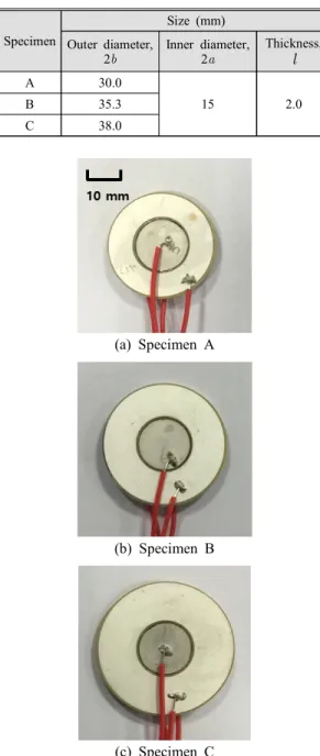
The diameter and thickness of the transducer speci-
mens composed of the piezoelectric discs are listed
in Table 1. The outer diameter is 10 times larger than the thickness. Three specimens are shown in Fig. 2.
The interior disc material is PZT-4. This material is a hard piezoelectric ceramic usually used in ultra- sonic actuators. The exterior disc material is PZT-5A.
This material is a soft piezoelectric ceramic usually
used in ultrasonic sensors. Their properties are well known and listed in Table 2. The material properties in Table 2 were converted for insertion into the equa- tions, and the resulting properties
(22)are in Table 3.
Properties Values
PZT-4 PZT-5A
Mechanical
Mass density
(×10
3kg/m
3) ρ 7.60 7.70
Elastic compliance (×10
-12m
3/N)
12.30 16.40
-4.05 -5.74
-5.31 -7.22
15.50 18.80
39.0 47.5
32.9 44.3 Dielectric Relative
permittivity
635 830
Electro- mechanical
Piezoelectric strain constant
(×10
-12C/N)
d
31-123.0 -171.0
d
33289 374
d
15496 584
Table 2 Material properties of PZT-4 and PZT-5A
Properties Values
PZT-4 PZT-5A
Mechanical Elastic stiffness (×10
9N/m
2)
139.0 120.4
77.8 75.2
74.3 75.1
115.4 110.9
25.6 21.1
30.6 22.6 Dielectric Permittivity
(×10
-9C
2/N⦁m
2)
5.62 7.35 Electro-
mechanical
Piezoelectric stress constant
(C/m
2)
e
31-5.20 -5.40 e
3315.10 15.80 e
1512.70 12.30
Table 3 Material properties of PZT-4 and PZT-5A,converted from the properties in Table 2
Radial mode number k
1a values q = 2.0 q = 2.4 q = 2.5
1 0.96 0.80 0.74
2 2.47 2.09 1.94
3 3.99 3.33 3.07
Table 4 The values of k1
a calculated from the charac-
teristic equationSpecimen
Size (mm) Outer diameter,
2b
Inner diameter, 2a
Thickness, l
A 30.0
15 2.0
B 35.3
C 38.0
Table 1 Sizes and material of piezoelectric disc speci- mens
(a) Specimen A
(b) Specimen B
(c) Specimen C
Fig. 2 Specimens of an ultrasonic transducer
The unknown variable k
1a in the characteristic equation
(12)can be determined using a numerical tool.
We used Mathematica
(23)in this work. The calculated results are displayed in Table 4.
3.2 Finite-element Analysis
The theoretical analysis explained in Section 2 has the advantage that the expressions can be con- veniently used to calculate the natural frequencies and mode shapes. However, the analysis has the disadvantage that the real physical phenomenon was simplified by some assumption. Therefore, the theo- retical analysis was complemented using a finite el- ement analysis. Then the analysis results were com- pared with the experimental ones.
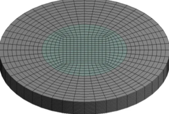
We used a commercial software ANSYS to cal- culate natural frequencies and mode shapes. Modal analysis and harmonic analysis were carried out with suitable boundary conditions. Mechanically, all outer boundaries are traction free. Electrically, a uniform electric field is formed in the thickness direction by the electrodes on the top and bottom surfaces of the transducer. The analysis model of specimen A is shown in Fig. 3 for example. It consists of 10 668 nodes and 9504 SOLID185 elements.
The results of the harmonic analysis are displayed in Fig. 4 in the form of impedance curves for three specimen models. The curves of impedance magni- tude indicate the resonances of the transducers at the minimum points.
4. Experiments
This section experimentally determines the ultra- sonic transducer vibration characteristics using two methods. The specimens used in the experiments were listed in Table 1 and shown in Fig. 2.
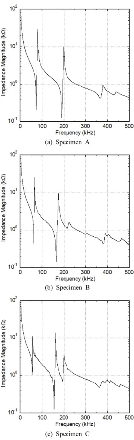
4.1 Impedance Analysis
We used an impedance analyzer (Agilent Techno- logy 4192A) to measure natural frequencies. Measure- ments were carried out with three pieces of three kind specimens. The experimentally obtained impe- dance curves using one piece of three specimens are displayed in Fig. 5. The minimum points of the impedance magnitude curves indicate the resonances.
4.2 Laser In-plane Interferometry
The shape of the first radial mode was measured by laser interferometry. We used a laser in-plane vibrometer, which consists of Polytec LSV-065-306F optical sensor head and Polytec OFV-3320 controller.
As described in Ref. [5], the apparatus measured the velocity of the moving plane normal to the central
Fig. 3 A finite element model of specimen A
Fig. 4 Impedance curves obtained by finite-element analysis of ultrasonic transducer of two piezo- electric discs of various thicknesses
line of laser beams. The experimental equipment was connected as shown in Fig. 6.
A waveform generator (Agilent 33220A) generated electric signals with variable frequencies and a con- stant voltage onto a transducer. The controller output was monitored on B&K 2035 signal analyzer. The measured amplitude was proportional to the vibration velocity, and it was converted to the vibration dis- placement. The measurement was performed along a radial line from the center to the outside at every 1 mm. The vibration amplitude was measured and normalized to the maximum amplitude.
4.3 Transmission and Reception of Ultrasound
Other experiment was performed to demonstrate the separate transmission and reception of ultrasound in a transducer. The experimental equipment was com- posed of the devices as shown in Fig. 7. The trans-
(a) Specimen A(b) Specimen B
(c) Specimen C
Fig. 5 Impedance curves obtained by experiment
Fig. 6 Experimental equipment with a laser in-plane vibrometer
Fig. 7 Experimental equipment for wave transmission and reception
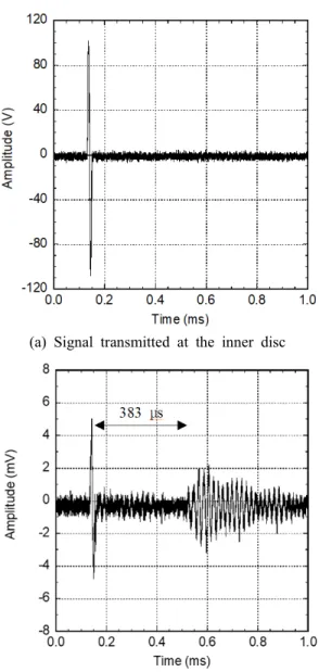
ducer specimen chosen for the experiment is type C in Table 1. The interior solid disc of the transducer is a transmitter, and it is excited by the high fre- quency signal generated and amplified by a wave- form generator and high voltage amplified, respec- tively. The signal is one-period harmonic wave of 55 kHz, which corresponds to the fundamental fre- quency of the transducer. Fig. 8(a) shows the signal exciting the interior solid disc of the transducer.
Second transducer of same type was located at a specific distance from the first transducer. The exterior hollow disc detects the ultrasound and converts it to the electric signal. Fig. 8(b) shows an example of the received signal monitored at the oscilloscope.
The time 383 μs corresponds to the flight time of the wave to 130 mm at the speed 340 m/s with the error less than 1 %.
5. Results
Natural frequencies calculated from Eq. (14) are listed in Tables 5, 6 and 7 for various values of the
(a) Signal transmitted at the inner disc
(b) Signal received at the outer disc of the transducer apart 130 mm from the first one Fig. 8 Ultrasound signals transmitted and received at
the transducer (type C in Table 1)
Radial mode number
Fundamental frequency (kHz)
Calculation FEA Measurement
1 70.6 70.6 70.3±1.2
2 181.8 180.6 184.7±1.2
3 293.2 288.7 -
Table 5Comparison of radial mode natural frequencies obtained by theoretical calculation, finite ele- ment analysis, and measurement for specimen A(q = 2.0)
Radial mode number
Fundamental frequency (kHz)
Calculation FEA Measurement
1 59.1 59.2 60.1±1.4
2 153.6 153.1 164.2±0.3
3 244.5 241.8 -
Table 6Comparison of radial mode natural frequencies obtained by theoretical calculation, finite ele- ment analysis, and measurement for specimen B(q = 2.4)
Radial mode number
Fundamental frequency (kHz)
Calculation FEA Measurement
1 54.6 54.7 55.2±0.8
2 142.4 142.1 153.3±0.9
3 225.7 224.6 -
Table 7Comparison of radial mode natural frequencies obtained by theoretical calculation, finite ele- ment analysis, and measurement for specimen C(q = 2.5)
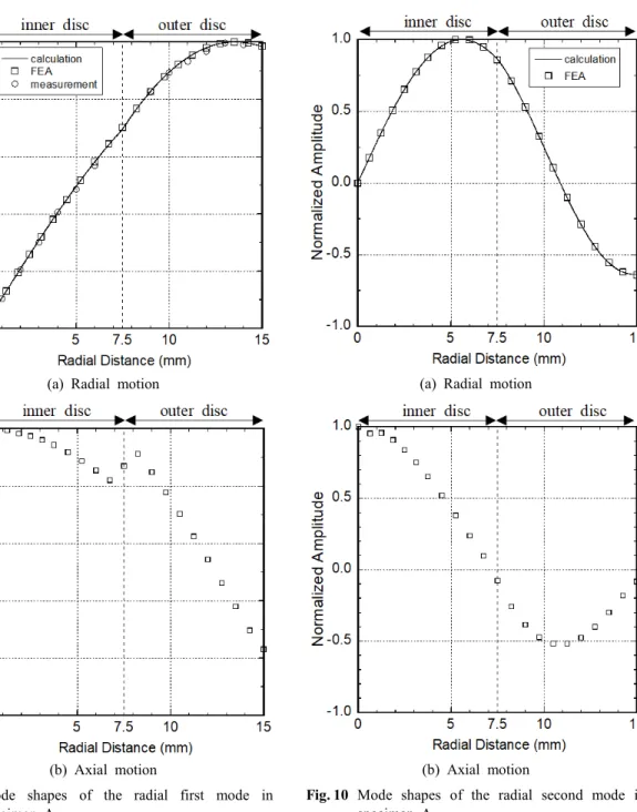
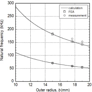
radius ratio q. They are compared with the finite el- ement analysis and experimental results in the ta- bles and discussed in Section 6. Mode shapes are calculated from Eqs. (8) and (13), and the results are displayed in Figs. 9(a) and 10(a).
The first mode shape is compared with the finite element analysis and experimental results in Fig. 9(a)
and discussed in Section 6.
Figs. 9 and 10 display the mode shapes of the ra- dial and axial vibrations in the radial first and sec- ond modes. The axial vibration in the interior disc would be used to radiate ultrasound into the air. The axial vibration in the exterior disc would be used to detect ultrasound from the air.
(a) Radial motion
(b) Axial motion
Fig. 10 Mode shapes of the radial second mode in specimen A
(a) Radial motion
(b) Axial motion
Fig. 9 Mode shapes of the radial first mode in specimen A
6. Discussions
The natural frequencies and mode shapes ob- tained theoretically in Section 3 and experimentally in Sections 4 are compared with each other in this section.
The natural frequencies of the in-plane radial modes obtained by calculations, finite element anal- ysis, and measurements are listed in Tables 5, 6 and 7 for three specimens. The theoretical and experi- mental results agree well within a 3.2 % discrep- ancy of each other. The natural frequencies listed in Tables 5, 6 and 7 are displayed in Fig. 11. It is clearly shown that the natural frequencies are small- er when the outer radius of the piezoelectric disc is larger. This trend is same as that observed for a single piezoelectric disc
(5).
The radial in-plane motion of the first radial mode obtained using the laser vibrometer was com- pared with the calculated results in Fig. 9(a). It is observed that the results agree well within 1.0 % with each other. In addition, the displacement dis- tribution was not monotonic from the center to the outer surface. The location of the maximum ampli-
tude is 0.7 % away from the perimeter, as observed in a single disc
(5).
If the material of the exterior disc is same as that of the interior disc, the characteristics of the trans- ducer are the same as those of a single piezoelectric disc. This statement was confirmed by repeating the calculations and measurements of natural frequencies with the specimens of interior and exterior discs made of PZT-4 only. The results, listed in Tables 8, 9 and 10, were compared with the natural frequencies of a single piezoelectric disc having the same radius as the outer radius of the exterior hollow disc.
Fig. 11Comparison of natural frequencies obtained by calculations, finite element analysis, and meas- urements for the radial first and second modes of three specimens
Radial mode number
Fundamental frequency (kHz) Calculation FEA Measurement Single disc
(calculation)
1 75.9 74.7 67.7±1.2 76.1
2 198.2 184.9 177.3±2.1 198.4
3 315.1 268.8 - 315.3
Table 8Comparisonofradialmodenatural frequencies obtained by theoretical calculation, finite ele- ment analysis, and measurement for specimen A made of PZT-4
Radial mode number
Fundamental frequency (kHz) Calculation FEA Measurement Single disc
(calculation)
1 64.5 64.7 57.7±2.5 64.7
2 168.5 162.6 160.1±6.1 168.6
3 267.8 245.5 - 268.0
Table 9Comparisonofradialmodenatural frequencies obtained by theoretical calculation, finite ele- ment analysis, and measurement for specimen B made of PZT-4
Radial mode number
Fundamental frequency (kHz) Calculation FEA Measurement Single disc
(calculation)
1 60.0 59.6 54.7±0.6 60.1
2 156.5 149.4 146.3±1.0 156.7
3 248.8 225.6 - 248.9
Table 10Comparisonofradialmodenatural frequencies obtained by theoretical calculation, finite ele- ment analysis, and measurement for specimen C made of PZT-4
7. Conclusions
This research presented the vibration characteristics of an ultrasonic transducer composed of interior and exterior piezoelectric discs. In-plane radial vibration characteristics were investigated theoretically and ex- perimentally, and natural frequencies and mode shapes were compared.
In the theoretical analysis, the equations of piezo- electric motions were derived by using radial dis- placements and electric potential. With boundary con- ditions the equations were solved and produced cha- racteristic equations providing the natural frequencies and mode shapes. In the experiments, the natural fre- quencies were measured at an impedance analyzer and the first radial in-plane mode were measured using a laser in-plane vibrometer. The theoretical and experi- mental results agreed with each other within 1.0 %.
Experiments also confirmed that the transducer trans- mits ultrasound at the interior disc and receives it at the exterior disc.
Similarly as observed in a single piezoelectric disc, the radial vibration distribution of the first mode was not monotonic from the center to the outer surface, and the maximum amplitude appears 0.2 % away from the outer surface. We found that the character- istics of the transducer is similar to those of a single piezoelectric disc.
The frequencies of the radial modes were shown as a function of outer radius of the disc. It is con- cluded that the vibration in the interior solid disc would radiate ultrasound into air and that in the ex- terior hollow disc would detect ultrasound from air.
References
(1) Busch-Vishniac, I. J., 1999, Electromechanical Sensors and Actuators, Springer, New York, pp. 140~154.
(2) Lynnworth, L. C., 1989, Ultrasonic Measurements for Process Control, Academic Press, Boston, pp. 487~507.
(3) Alonso, L., Milantes, V., Torre-Ferrero, C., Godoy, J., Oria, J. P. and Pedro, T., 2011, Ultrasonic Sensors
in Urban Traffic Driving-aid Systems, Sensors, Vol. 11, No. 1, pp. 661~673.
(4) Shrivastava, A. K., Verma, A. and Singh, S. P., 2010, Distance Measurement of an Object or Obstacle by Ultrasound Sensors Using P89C51RD2, International Journal of Computer Theory and Engineering, Vol. 2, No. 1, pp. 64~68.
(5) Kim, D. J., Oh, S. H. and Kim, J. O., 2015, Measurements of Radial In-plane Vibration Characteris- tics of Piezoelectric Disc Transducers, Transactions of the Korean Soc. for Noise and Vibration Engineering, Vol. 25, No. 1, pp. 13~23.
(6) Piao, C. and Kim, J. O., 2014, In-plane Vibration Characteristics of Piezoelectric Ring Transducers, Transactions of the Korean Soc. for Noise and Vibration Engineering, Vol. 24, No. 10, pp. 780~787.
(7) Li, H. H., Hu, J. H. and Chan, H. L. W., 2004, Finite Element Analysis on Piezoelectric Ring Trans- former, IEEE Transactions on Ultrasonics, Ferroelectrics, and Frequency Control, Vol. 51, No. 4, pp. 1247~1254.
(8) Meitzler, A. H., O’Bryan, Jr., H. M. and Tiersten, H. F., 1973, Definition and Measurement of Radial Mode Coupling Factors in Piezoelectric Ceramic Materials with Large Variations in Poisson’s Ratio, IEEE Transactions on Sonics and Ultrasonics SU-20, Vol. 12, No. 1, pp.
233~239.
(9) Kunkel, H. A., Locke, S. and Pikeroen, B., 1990, Finite-element Analysis of Vibrational Modes in Piezo- electric Ceramic Disks, IEEE Transactions on Ultrasonics, Ferroelectrics, and Frequency Control, Vol. 37, No. 4, pp. 316~328.
(10) Lee, P. C. Y., Yu, J.-D., Li, X. and Shih, W.-H., 1999, Piezoelectric Ceramic Disks with Thickness-graded Material Properties, IEEE Transactions on Ultrasonics, Ferroelectrics, and Frequency Control, Vol. 46, No. 1, pp. 205~215.
(11) Ho, S.-T., 2007, Modeling of a Disk-type Piezo- electric Transformer, IEEE Transactions on Ultrasonics, Ferroelectrics, and Frequency Control, Vol. 54, No. 10, pp. 2110~2119.
(12) Lin, Y.-C. and Ma, C.-C., 2004, Experimental Measurement and Numerical Analysis on Resonant Cha- racteristics of Piezoelectric Disks with Partial Electrode Designs, IEEE Transactions on Ultrasonics, Ferroelectrics, and Frequency Control, Vol. 51, No. 8, pp. 937~947.
(13) Iula, A., Lamberti, N. and Pappalardo, M., 1996, A Model for the Theoretical Characterization of Thin Piezoceramic Rings, IEEE Transactions on Ultrasonics, Ferroelectrics, and Frequency Control, Vol. 43, No. 3, pp. 370~375.
(14) Ho, S.-T., 2007, Modeling and Analysis on Ring- type Piezoelectric Transformers, IEEE Transactions on Ultrasonics, Ferroelectrics, and Frequency Control, Vol.
54, No. 11, pp. 2376~2384.
(15) Piao, C. and Kim, J. O., 2016, Vibration Charac- teristics of a Piezoelectric Disk Laminated with an Elastic Disk, Journal of Mechanical Science and Technology, Vol. 30, No. 12, pp. 5351~5362.
(16) Piao, C. and Kim, J. O., 2017, Vibration Charac- teristics of an Ultrasonic Transducer of Two Piezoelectric Discs, Ultrasonics, Vol. 74, pp. 72~80.
(17) Guo, N., Cawley, P. and Hitchings, D., 1992, The Finite Element Analysis of the Vibration Characteristics of Piezoelectric Discs, Journal of Sound and Vibration, Vol. 159, No. 1, pp. 115~138.
(18) Heyliger, P. R. and Ramirez, G., 2000, Free Vibration of Laminated Circular Piezoelectric Plates and Discs, Journal of Sound and Vibration, Vol. 229, No. 4, pp. 935~956.
(19) Wang, L. K., Wang, G. and Dong, T. X., 2011, Analyses for Radial Vibration of Piezoceramic Disc Stack, Ferroelectrics, Vol. 413, No. 1, pp. 443~451.
(20) Laoratanakul, P. and Uchino, K., 2004, Designing a Radial Mode Laminated Piezoelectric Transformer for High Power Application, IEEE International Ultrasonics, Ferroelectrics, and Frequency Control Joint 50th Anniver- sary Conference, pp. 229~232.
(21) Achenbach, J. D., 1975, Wave Propagation in Elastic Solids, North Holland, Amsterdam, pp. 73~75.
(22) Hussein, M. and Heyliger, P. R., 1996, Discrete Layer Analysis of Axisymmetric Vibrations of Laminated Piezoelectric Cylinders, Journal of Sound and Vibration, Vol. 192, No. 5, pp. 995~1013.
(23) Wolfram, S., 1999, The Mathematica Book, 4th ed., Wolfram Media Inc., Champaign, pp. 100~107.
Appendix
A.1 Piezoelectric Constitutive Equations Piezoelectric relations were well formulated from
the general electromechanical relation
(1). The piezo- electric constitutive equations are expressed as fol- lows:
T cES eTE
(A1)
D e S SE
(A2)
where T, S, D, and E are the matrix forms of stress- es, strains, electric displacements, and electric fields, respectively. In addition, e is the matrix form of piezoelectric stress constants, c
Eis the coefficient matrix of stiffness with a constant electric field, and ε
Sis the matrix of permittivity with constant strain.
Vibrations with axisymmetry can be formulated with cylindrical coordinates r, θ z, and time t in terms of radial displacement u (r, z, t) and axial dis- placement w (r, z, t). Normal strains ε
r, ε
θ, ε
zand shear strains γ
θz, γ
zr, γ
rθare related as follows:
(A3a,b,c)
(A4a,b,c)
Electric field E
zis related with electric potential ϕ (z, t) in the piezoelectric transducer as follows:
(A5)
Eqs. (A3) ~ (A5) are inserted in Eqs. (A1) and (A2) and they yield normal stresses σ
r, σ
θ, σ
z, and electric displacement D
zas follows
(8):
(A6a)
(A6b)
(A6c)
(A6d)
(A6e)
A.2 Constitutive Equations under Plane Stress Condition
When the thickness of a disc is much larger than its diameter, i.e. the diameter-to-thickness ratio is bigger than 10, the disc is assumed to satisfy plane stress conditions in the thickness direction, and thus, σ
z= 0. Eq. (A6c) is rewritten to present the normal strain ε
Sas
(8):
(A7)
Eq. (A7) is inserted in Eqs. (A6a), (A6b) and (A6e) and they are rewritten as follows:
(A8a)
(A8b)
(A8c)
In Eq. (A8) superscript p is used to define the constants as follows:
(A9a)
(A9b)
(A9c)