Superconductivity and Cryogenics Vol.12, No.2, (2010), pp.21~24
```
Abstract-- This paper deals with numerical analysis on a high-Tc superconducting (HTS) electrodynamic suspension (EDS) simulator according to the variation of the ground conductor conditions. Because the levitation force of EDS system is formed by the magnetic reaction between moving magnets and fixed ground conductors, the distribution of the magnetic flux on a ground conductor plays an important role in the determining of the levitation force level. The possible way to analyze HTS EDS system was implemented with 3D finite element method (FEM) tool. A plate type ground conductor generated stronger levitation force than ring type ground conductor. Although the outer diameter of Ring3 (335 mm) was larger than that of Ring2 (235 mm), the levitation force by Ring2 was stronger than that by Ring3. Considering the results of this paper, it is recommended that the magnetic flux distribution according to the levitation height and magnet current should be taken into account in the design of the ground conductors.
1. INTRODUCTION
The basic mechanism of the propulsion of the traditional train is the friction between moving iron wheel and rail.
Because of friction, a traditional train system is inevitably marked with several innate problems such as the limit of acceleration and deceleration, noise, and safety at high speed. Many engineers believe that the maximum speed of a commercial wheel-on-rail train is 350 km/h [1]. The basic mechanism of the magnetic levitation (maglev) train is magnetically levitated train and propulsion with linear electric motor. There is no friction between levitated train and any part in the maglev train system. Therefore maglev train can solve the problems of the traditional wheel-on-rail train.
Japanese superconducting maglev train MLX01 has the world record in the speed of the train. It reached to 581 km/h [2-4]. Japanese high speed superconducting maglev train system will be constructed between Tokyo and Nagoya until 2015. The budget of nine trillion yen will be invested in this project [5].
As a basic research for a high speed superconducting maglev train, a numerical simulation to analyze the characteristics of superconducting EDS system was imple-
* Corresponding author: dkbae@cjnu.ac.kr
mented with 3D FEM. Four analytic models were used in this simulation. The variation factor in the analysis was ground conductor. One plate type ground conductor and 3 ring type ground conductors were modeled and simulated.
2. ANALYTIC MODELS 2.1. HTS Magnet
The eddy current in the ground conductor is proportional to linked magnetic flux and its change rate to time. The magnitude of it is a function of geometry of magnet with ground conductors and the change rate is a function of velocity of levitated magnet.
In EDS system, the levitation force Fl(t) between moving HTS magnet and ground conductor can be expressed as
y d
t y x t dM i t
Fl
, ) , ) (
( )
( 2 (1)
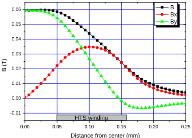
where i(t) is current in superconducting winding and M(x, y, t) is the mutual inductance between HTS winding and its image at a distance y(t). y is the direction which is normal to ground conductor surface and x is moving direction of HTS magnet [6]. In equation (1), it is shown that levitation force is a function of changing rate of By. In other words, the distribution of By should be considered in the design of the levitation magnet for EDS system.
Table I shows the specifications of the HTS levitation magnet. Bi-2223 reinforced wire from AMSC was used in the winding. The magnet consists of two double-pancake coils. Each pancake was separated by 2 mm thick GFRP plate. The length of the used wire in the winding was 800 m.
The inner diameter of the winding was 100 mm and the outer diameter was about 317 mm.
2.2. FEM Modeling
Fig. 1 shows the analytic models and table 2 shows the specifications of ground conductors. (a), (b), (c), and (d) of Fig. 1 illustrate the shapes of used 4 models, representing the application of Plate, Ring1, Ring2, and Ring3 ground conductors, respectively. As shown in table II, the thickness of each ground conductor was 35mm. The width
Characteristic Analysis of HTS EDS System with Various Ground Conductors
Duck Kweon Bae1,* and Tae Kuk Ko2
1Dept. of Safety Engineering, Chungju National University, Chungju, Korea
2School of Electric and Electronic Engineering, Yonsei Univertity, Seoul Korea Received 8 April 2010; accepted 6 May 2010
Characteristic Analysis of HTS EDS System with Various Ground Conductors
of Plate was 262 mm. The outer diameter of Ring1, Ring2, and Ring3 was respectively 135, 235, and 335 mm. The material of the all ground conductors were pure aluminum.
The conductivity of the ground conductor was 3.8e7 Siemens/meter.
To simulate EDS system, AC current was flowed in the HTS magnet. The frequency of the current was 5, 10, 20, 40, 60, 100, 150, and 200 Hz. 10, 20, 30, and 40 Apeak were flowed at each condition. The gap between HTS magnet and ground conductor was 20 mm.
3. LEVITATION FORCE
Fig. 2 shows the distribution of By below the HTS magnet [7]. MagNet from Infolytica Corporation was used in this calculation. As shown the figure, By became 0 T at r=146 mm, which was smaller than the outer radius of HTS winding. In other words, the direction of By in conducting area of Ring3 was not same. It was expected that the direction change of By in Ring3 would affect to the strength of the levitation force.
TABLE I
SPECIFICATIONS OF HTS MAGNET.
Parameter Specification
Number of layer 4
Inner diameter 100 mm
Outer diameter 317 mm
Number of turns 1244 turns (311 turns/layer)
Inductance 279.4 mH
TABLE II
SPECIFICATIONS OF GROUND CONDUCTORS. Specification
Plate Thickness 35 mm
Width 262 mm
Length 700 mm
Ring1 Thickness 35 mm
Inner diameter 65 mm
Outer diameter 135 mm
Ring2 Thickness 35 mm
Inner diameter 165 mm
Outer diameter 235 mm
Ring3 Thickness 35 mm
Inner diameter 265 mm
Outer diameter 335 mm
(a) Model with Plate ground conductor
(b) Model with Ring1ground conductor
(c) Model with Ring2 ground conductor
(d) Model with Ring3 ground conductor Fig. 1. Analytic models.
22
Duck Kweon Bae and Tae Kuk Ko
0.00 0.05 0.10 0.15 0.20 0.25
-0.01 0.00 0.01 0.02 0.03 0.04 0.05 0.06
B (T)
Distance from center (mm)
B Bx By
HTS winding
Fig. 2. Magnetic flux density of ground conductor at 30 mm below the HTS magnet.
0 50 100 150 200
0 10 20 30 40 50 60 70 80
Force (N)
Frequency (Hz)
Plate Ring1 Ring2 Ring3
Fig. 3. Calculated levitation force with 10 A current (levitation height: 20 mm).
0 50 100 150 200
0 50 100 150 200 250 300 350
Force (N)
Frequency (Hz)
Plate Ring1 Ring2 Ring3
Fig. 4. Calculated levitation force with 20 A current (levitation height: 20 mm).
Fig. 3, 4, 5, and 6 show the calculated levitation force with Plate (262 mm width and 35 mm thickness plate type aluminum ground conductor), Ring1 (65mm inner diameter, 135 mm outer diameter and 35 mm thickness ring type ground conductor), Ring2 (165mm inner diameter, 235 mm outer diameter), and Ring3 (265mm inner diameter, 335
mm outer diameter and 35 mm thickness ring type ground conductor). Because the plate type ground conductor has the largest area, which need to link magnetic flux, the levitation force of Plate was stronger than other three cases.
As shown in the Fig. 3, 4, 5, and 6, the levitation force became saturated after 50 Hz of current frequency. The increasing rate of the levitation force via current frequency was decreased after 10 Hz. After 60 Hz, the increasing ratio of levitation force became linear. The calculated levitation force was proportional to the square of the transport current.
Although Ring3 was larger than Ring2, the levitation force of Ring2 was stronger than that of Ring3. The reason was that the linked magnetic flux of Ring2, due to the distribution of magnetic flux difference, was larger than that of Ring3. At 100 Hz of current frequency, the levitation force of Ring2 was 905 N and that of Ring1 and Ring3 were respectively 350 N and 670N at the same frequency.
Because the levitation force is the result from the reaction between levitation magnet and ground conductor, the design of the ground conductor is important to the performance and construction cost of maglev train system.
Especially, the consideration of the cost is of significant importance to the commercialization of the maglev system.
0 50 100 150 200
0 100 200 300 400 500 600 700
Force (N)
Frequency (Hz)
Plate Ring1 Ring2 Ring3
Fig. 5. Calculated levitation force with 30 A current (levitation height: 20 mm).
0 50 100 150 200
0 200 400 600 800 1000 1200 1400
Force (N)
Frequency (Hz)
Plate Ring1 Ring2 Ring3
Fig. 6. Calculated levitation force with 40 A current (levitation height: 20 mm).
23
Characteristic Analysis of HTS EDS System with Various Ground Conductors
0 50 100 150 200 250
0 10 20 30 40 50 60 70 80
Force (N)
Frequency (Hz)
Simulation Experiment
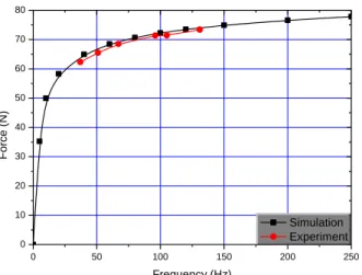
Fig. 7. Comparison of results from simulation and experiment (peak current: 10A).
In this point of view, the ring type ground conductor is more economical. Based on the calculation of this study, magnetic simulation considering the levitation height must be taken into consideration in the design process of the ring type ground conductor.
Fig. 7 shows the simulation and experimental results with Plate. The current in the magnet was 10 Apeak. In the simulation, the gap between HTS levitation magnet and the ground conductor was 20 and 30 mm. The frequencies in the experiment were 37, 51, 67, 96, 105, and 131 Hz. As shown in the figure, the results from numerical simulation were in agreement with the experimental results.
4. SUMMARY
In this paper, the levitation characteristics of the HTS EDS system, which is a strong candidate for a high speed maglev train was analyzed with the variation of ground conductor. The levitation force became saturated after certain current frequency level (50 Hz in this paper). The increasing rate of the levitation force via current frequency was decreased after a certain frequency level (10 Hz in this paper). The levitation force of HTS EDS system was proportional to the square of the magnet current. Although Ring 3 was larger than Ring2 the levitation force of Ring2 was stronger than that of Ring3. The reason was that the linked magnetic flux of Ring2, due to the distribution of magnetic flux difference, was larger than that of Ring3. The data obtained in this study can be used in the design of high speed HTS EDS maglev train.
ACKNOWLEDGMENT
This work was supported by the Human Resources Development Program of the Korea Institute of Energy Technology Evaluation and Planning (KETEP) grant funded by the Korea government Ministry of Knowledge Economy. (No. 2007-P-EP-HM-E-08-0000)
REFERENCES
[1] Kazuo Sawada, "Superconducting Maglev Developed by RTRI and JP Central," Japan Railway and Transport Review 25, pp. 58-61, 2000.
[2] Motoharu Ono, Shunsaku Koga, and Hisao Ohtsuki, "Japan's Superconducting Maglev Train," IEEE Instrumental &
Measurement Magazine, pp. 9-15, 2002.
[3] Donald M. Rote and Eddie M. Leung, "Future Prospects for Maglev Technology Applications," Proceedings of MAGLEV'2004 Conference, Shanghai, China, pp. 65- 75, Oct. 26-28, 2004.
[4] A. Cassat and M. Jufer, "MAGLEV Projects Technology Aspects and Choices," IEEE Trans. on Applied Supercon ductivity, Vol. 12, No. 1, pp. 915-925, 2002.
[5] Available from: http://news.khan.co.kr/kh_news/kh an_art_view.
html? artid=200704271821071 &code=970203.
[6] P. K. Sinha, Electromagnetic Suspension Dynamics & Control, Peter Peregrinus Ltd., 1987.
[7] Duck Kweon Bae, Hungje Cho, and Jongmin Lee, "Characteristic Analysis of HTS Levitation Force with Various Conditions of Ground Conductors," IEEE Transactions on Applied Superconductivity, Vol. 18, No. 2, pp. 803-807, 2008.
24