Weather Radar Image Generation Method Using Interpolation based on CUDA
Liu Yang†, Bong-Joo Jang††, Sanghun Lim†††, Ki-Chang Kwon††††, Suk-Hwan Lee†††††, Ki-Ryong Kwon††††††
ABSTRACT
Doppler weather radar is an important tool for meteorological research. Through several decades of development, Doppler weather radar has enormous progress in understanding, detection and warning of meso and micro scale weather system. It makes a significant contribution to weather forecast and weather disaster warning. But the large amount of data process limits the application of Doppler weather radar.
This paper proposed for fast weather radar data processing based on CUDA. CDUA is a powerful platform for highly parallel programming developed by NVIDIA. Through running plenty of threads, radar data can be calculated at same time. In experiment, CUDA parallel program can significantly improve weather data processing time.
Key words: CUDA, Weather radar image, Image generation, Image interpolation
※ Corresponding Author : Ki-Ryong Kwon, Address:
(608-737) Yongso-ro 45, Nam-Gu, Busan, Korea, TEL : +82-51-629-6257, FAX : +82-51-629-6230, E-mail : [email protected]
Receipt date : Nov. 12, 2014, Revision date : Mar. 20, 2015 Approval date : Apr. 9, 2015
††††Department of IT Convergence and Application Engineering, Pukyong National University (E-mail : [email protected])
††††Korea Institute of Civil Engineering and Building Technology (E-mail : [email protected])
††††Korea Institute of Civil Engineering and Building Technology (E-mail : [email protected])
††††Dept. of IT Cooperative System, Gyeongbuk Provin- cial College (E-mail : [email protected])
††††††Department of Information Security, Tongmyong University (E-mail : [email protected])
††††††Department of IT Convergence and Application Engineering, Pukyong National University
※ This research was supported by a grant from a Strategic Research Project (Development of a road weather information retrieval system based on automo- tive sensors) funded by the Korea Institute of Civil Engineering and Building Technology and the framework of IT/SW Creative research program supervised by the NIPA (National IT Industry Promotion Agency) (NIPA- 2014) and Basic Science Research Program through the National Research Foundation of Korea (NRF) funded by the Ministry of Education, Science and Technology (NRF-2014R1A1A4 A01006663).
1. INTRODUCTION
Radar detecting technology is gradually in- troduced into meteorological fields since the early
‘50s. So far, weather radar has become one of the important observation equipment, it plays an influ- ential role in weather forecast and severe weather warning. Statistical results show that the reasons of most of flood disaster are because of meso and micro scale rainstorm. So an accuracy, real time forecast and description of severe convection weather are meaningful for people to reduce and prevent weather disasters. The development of ra-
dar technology is briefly divided into three phases, conventional weather radar, digital weather radar and Doppler weather radar. Meanwhile there are three corresponding researching phases. The key point of meteorological radar researching is area precipitation estimation and wind field information by radar wave.
Until ‘80s conventional radar was still being used in meteorological study. It can show the in- tensity of precipitation but not accurate as Doppler radar, because besides measuring the precipitation, Doppler radar can measure the wind field in- formation, like speed and direction. A new gen-
eration weather radar network named CASA (the Collaborative Adaptive Sensing of the Atmo- sphere) has utilized a kind of X-band short range radar, unlike conventional weather radar networks usually use high-power, long-range radars. The new Doppler weather radar networks overcome the weaknesses of conventional radar which are high frequency attenuation and observation at the lower parts of the atmosphere. The acquired information by Doppler radar is much more than conventional radar, therefor the data from Doppler radar can be processed in time becomes an important factor for practical application in the future.
Recently, Many Radar applications are develop- ing in various fields(as [1]), so fast processing of radar data for end-users or service-providers is required. For improving the process time of weath- er radar imaging; Paper proposes a radar retrieval system from the radar source data files to radar images. Radar source data cannot be directly read by people, it needs be transformed to image, con- venient for future study with geographic in- formation system and others. Usually, radar source data is an “.uf” or “.nc”file. Following the com- pressed format, people can extract the specific data and write as a matrix, use normalization, the raw matrix data can be expressed as gray scale images.
As we known radar data is acquired the data of circle around, take PPI for example, if assimilate radar detecting area to an umbrella, the radar site locates the center of umbrella cover. Each radar ray is like rib, and panel of umbrella would denote the no detecting data area. In practice, the reflected intensity data on “ribs” can be found on raw radar gray images. But for the “panel” area, radar image does not have direct data, it is kind of data gaps, so people use different interpolation algorithm to fill these parts. This is the most computationally expensive step in radar imaging. But CUDA tech- nique can much improve this situation. CUDA technique provides by NVIDIA for writing highly parallel programs. It is based on GPU, as we
known GPU contains large amount of ALUs, by providing a large number of threads, memories, and synchronization, CUDA program will reduce much computing time. And paper’s experiment proved the effect of CUDA as well.
2. RELATED WORKS
Weather Radar can get the surrounding mete- orological information of radar site, through ana- lyzing the radar signal. Skolnik[2] and Richards[3]
have explained the physical and geometry princi- ple, and talked fundamental knowledge of radar in detail. This paper only focuses on digital process- ing part of radar imaging. Doppler radar uses the model of continuous volume scanning to detect 3D structure of clouds, one time scanning needs 6~10 minutes. Doppler radar can get the information of wind field, but a single Doppler radar can only get an average radial velocity. If require 2D or 3D structure of wind field, multi-Doppler radar joint detection is needed.
Usually In radar imaging field, Radar image has three display modes, PPI (Plan Position Indicator), RHI (Range Height indicator) and CAPPI (Const- ant Altitude Plan Position Indicator). Radar wave is not continuous; it is a few rays even distributed on an entire circumference surface. So the rays are tightness nearby radar station and sparse far away from radar station. With the distance between ad- jacent rays increasing, the no data area will occur.
Therefore an important step in radar imaging is needed, radar image interpolation. Different radar display modes can be seen as different grid frames, the job of radar imaging is that find the matching data fill the frame from source data, and estimate the super-resolution parts by using interpolation algorithm.
As previous mentioned, many grids in radar im- age needs to been interpolated. In practical applica- tions, there are several methods; thereinto bilinear interpolation is the most common interpolation al-
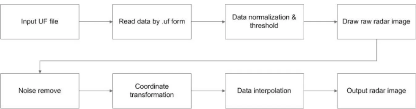
Fig. 1. Radar data retrieval flowchart.
gorithm[4]. The weakness is that two adjacent sampling sites get far, with the radial distance increasing. Then the difference of radar reflectivity will be big, and lead to discontinuity echo. It is not like Barnes interpolation etc. methods, which have better continuity. But the bilinear interpolation is still acceptable. On the other hand, radar idata in- terpolation is a time consuming task. Because of having the simplest operator, bilinear interpolation is the fast interpolation algorithm. This paper try to improve the processing time, so paper still choo- ses to simulate bilinear interpolation method for radar imaging.
Years ago, Shinozawa et al[5]. proposes the method to improve processing time by using paral- lel algorithm. Using Parallel method is proactive way to save time. Recently, CUDA technique pro- vides a convenience platform, GPU program. Based on having plenty ALUs GPU, CUDA can run mul- ti-threads on same time, and compute many com- plex computational problems[6]. It has already ap- plied in many areas, like video and audio process- ing, physics simulation, product design and medical imaging etc. and yielded significant results. Then the CUDA program is introduced here for improv- ing radar imaging.
3. PROPOSED WEATHER RADAR IMAGING BASED ON CUDA
3.1 Weather radar image format and generation Weather radar is used to detect the position, in-
tensity and variation of rainfall in atmosphere.
Because it is fast and accuracy to provide the in- formation of weather around the radar station, in mesoscale and smaller disastrous weather survey and short time weather forecasting, weather radar plays an important role.
When radar collects radar with stereoscopic form, radar raw data is in a spherical coordinate system which is centered in radar station. So when people need to synthetically analyze radar data and do some further processes, the raw radar data needs be transformed to radar image. In the simu- lation, there are three main steps: firstly read raw radar data following compressed format and draw a raw image, secondly transform raw image from spherical coordinate to Cartesian coordinate sys- tem, thirdly interpolate radar image with estimated intensity value. In this paper the whole process will follow a flowchart like Fig. 1. Involved key steps will be described in detail.
The radar raw data is stored in ‘.uf’ file. UF is short for ‘Universal Format’. Original contents are presented by Barnes[7] in 1980. It is specifically created for Doppler radar data. The specific struc- ture of files can be found from the IRIS manual[8].
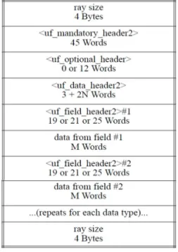
One file contains a complete volume scan. Within the file is a series of stand-alone rays. For single ray has the structure as following Fig. 2. Each ray belongs which sweep and volume is organized by the header’s information. Within a ray, the data is basically all 16 bits words.
The information of rays can be read a word by
Fig. 2. UF file structure.
Fig. 3. Raw radar reflection image (483*996).
Fig. 4. Coordiante mapping from spheroidal coordinate to Cartesian coordinate.
a word follow uf structure. Include the recoded time, location and setting information, and there are two kinds of reflected wave information which we are interested. They are labeled by CZ (Corre- cted reflectivity factor) and VT (Velocity thresh- olded on NC), respectively represent rainfall and wind velocity. These data are extracted from raw file and present by a gray image, each line presents a ray, and each pixel presents a gate value. The value of radar data need to be normalized matching the intensity of pixel. Then a raw radar image can be drawn like Fig. 3.
3.2 Weather radar imaging steps
As we known, radar sends off radar wave to
surrounding airspace. When radar finishes a round of scanning, a sweep record can be gotten. The track of sweep is a side surface of circular cone.
For further analysis, the data need to be mapped to a flat surface (Fig. 4). The mapping functions are as following:
×cos ×cos (1)
×sin ×cos (2) (x,y) is the location in Cartesian coordinate sys- tem, A denotes the azimuth, E denotes the ele- vation angle. After calculating 360 degrees around the radar site, a intuition display way for these data is the PPI. PPI is short for plan position indicator.
It is the most common type of radar display model.
As the radar antenna rotates, in PPI radar site is in the center of display, a radial trace on the sweep is presented.
A characteristic of PPI display is that the radar records are tightness nearby radar station and sparse far away from radar station. Because the time of radar recording is not continuous, the re- cords are not continuous neither in the space. And after coordinate transformation this kind of dis- continuous will appear. For observing, these va- cancies need to be filled. This is next step radar data interpolation.
3.3. Interpolation process–high computation time Radar data interpolation is an important step in radar retrieval process. As the most computation- ally expensive and radar image quality determining
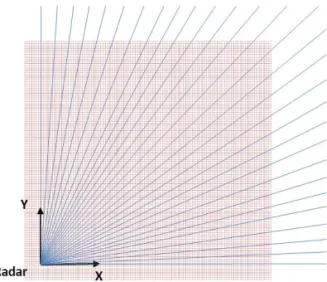
Fig. 5. Ray distribution sample in the first quadrant of Cartesian coordinate system, blue line though grids are known grid, the rest are not.
Fig. 6. The GPU Devotes more transistors to data processing [13].
step, many algorithms have been proposed like nearest neighbor mapping[9], bilinear interpolation [10] and Barnes interpolation[11] etc. After coor- dinate transformation there are only a few grids can find mapping value from raw radar image like Fig. 5. All of interpolating algorithms try to esti- mate the rest no value grids by different methods.
In this paper, the bilinear interpolation is simulated.
Bilinear interpolation is a frequently used and fast method for two dimensional data interpolation.
Assume that we try to estimate a value at the un- known point , there are four nearest known points,,,from two neighbor rays. Then bilinear interpolation estimate of the unknown value is given as:
(3)
3.4 Apply to CUDA interpolation process From previous contents mentioned, interpolation process needs process amount of repetitively computation. For instance, if a raw image with 1000*500 size is transformed to transform to PPI, without scale transformation, there will be more than × grids need to be reconstructed. In our experiments, 80~95 percentage of processing time is spent by interpolation process. An efficient way for interpolating processing time is bringing in a kind of massively parallel processing method, CUDA program. CUDA is short for compute uni- fied device architecture. It is a kind of software ar- chitecture for data parallel process developed by NVIDIA and use GPU as computing device.
NVIDIA’s CUDA architecture provides a powerful platform for writing highly parallel programs[12].
Look over the inside of GPU structure, GPU has more transistors area devoted to data processing rather than data caching and flow control. Unlike CPU is in charge of logical transaction and serial computation, GPU is well suited for compute-in- tensive, highly parallel computation. Just like what radar data retrieval system is about.
Before using CUDA program, with hardware part a NVDIA’s GPU at least after G80 architecture.
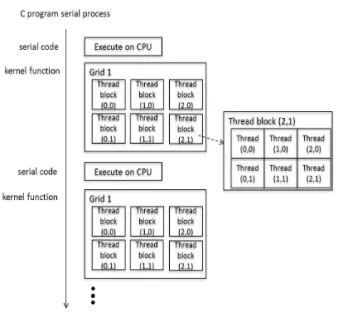
CUDA program model is like Fig. 7. CPU is the
Fig. 7. CUDA program model.
Fig. 8. Find radar data range by CUDA multi-threaded parallel process.
host, GPU is the device, and these two parts work together, respectively in charge of logical parts and parallel computing tasks. CPU and GPU have their own memory and independent of each other. After assign the tasks, the parallel parts will be handed over to GPU. The CUDA function which runs on GPU is named with kernel. A complete CUDA pro- gram consists of a series of kernels from device and serial processing from host. Before the kernel is executed some configuration information are needed, like size of memory, number of thread blocks and number of threads in block.
In theory, with single core CPU, the processing time for every sweep costs like × × . But in GPU, amount of repetitive data can be proc- essed at same time. A lot of time can be reduced through parallel processing. The sweep processing time can become like ∝log × × .
In radar retrieval process, there are two parts programed by CUDA code: data normalization and data interpolation. Because in the developing step, radar reflection intensity range is not clear, a clas- sic parallel application is used to find data range, the reduction algorithm. Not like CPU which com- pares input data one by one, GPU can finish the same function by comparing multithread at a same time (Fig. 8).
On one level many threads will be processed at same time, the bigger one will be copy to interval
× location; n is the number of comparing level. At the last the extreme value of a series of numbers will be copied to the front.
In radar data interpolation process, there are a variety of methods, Barnes interpolation, bilinear interpolation and the nearest neighbor interpolation etc. Each of them has different implement proce- dure, but when converts them to parallel process by CUDA, there is a basic processing model:1.
Allocate video memory on device; 2. Copy the im- age data from host memory to device memory; 3.
Configure kernel function, set number of threads and thread blocks; 4.run kernel function; 5. Copy output from device to host memory; 6. Output re- sults and release memory space. The task of paral- lel code is charge of the specific interpolation algo- rithm, which is realized function by kernel.
All parallel function is realized in kernel, so ker- nel’s code is directly related with the performance of program. Different interpolation algorithm may need different number of kernels, but the number should be reduced as few as possible for avoiding
(a) (b)
Fig. 9. Radar data interpolation (a) before interpolation, (b) after interpolation.
(a) (b)
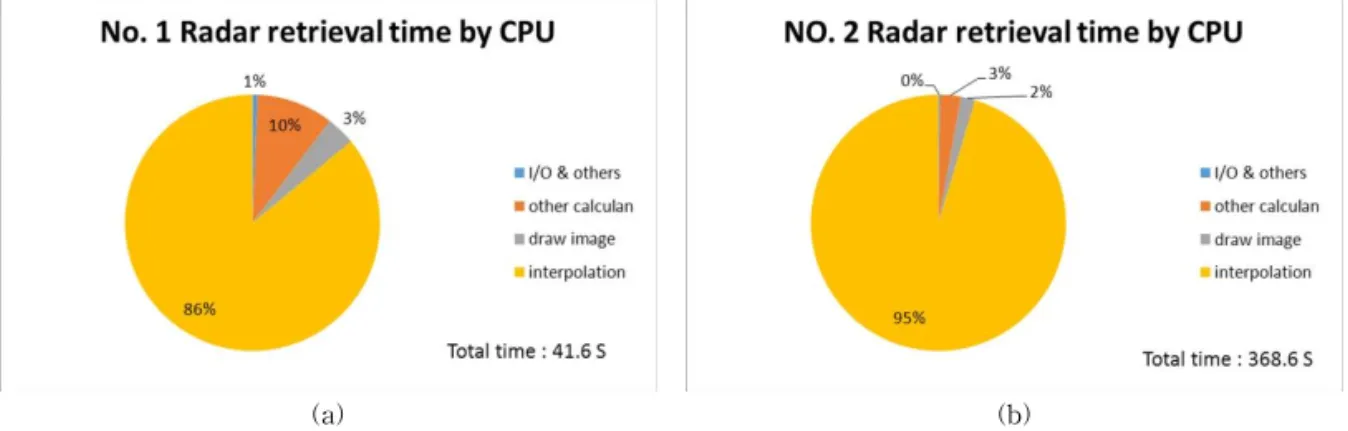
Fig. 10. Radar retrieval times with different size raw data (a) 147×426 raw image, (b) 483x996 raw image.
the data transmission between host and device. So in order to design a high efficient program, there are three issues should be thought: 1. avoid the da- ta transmission between different memory spaces;
2. maximize the use of all kinds of bandwidth, and make sure data alignment; 3. appropriately assign threads. Besides, after run a kernel function, the synchronous function need be executed. That can make sure all thread of device is end of run, make thread of CPU and GPU synchronous. About spe- cific contents of realized kernel is the previous in- terpolation part.
4. EXPERIMENTAL RESULTS
According to the head information of source da- ta, the input UF file was recorded by an X-band Doppler radar. The radar site locates Rush springs city, Oklahoma, USA. The record time is on May 14th 2009. The source file contains 10 sweeps data
of a volume, and the sweep model is PPI. File re- coded the corrected reflectivity factor CZ and ve- locity thresholded VE, which respectively reflect the possible rainfall intensity and wind speed.
Paper takes the first seep for example, retrieves the CZ factor on radar image.
The experiment platform is Intel Core i5 CPU with 4 cores 2.8 GHz, 3 GB ram. The graphic card is NVIDIA GeForce GT 220. The final retrieval re- sult is like Fig. 9. This presents the radar image before and after interpolation process. In the circle area of before interpolation image, the black pixels are no data parts. Comparing with these two im- ages, we can find that a huge number of pixels need to be interpolated. For instance, the ex- perimental image is 1000*1000 pixels; there are more than 2.6*106 pixels (grids) need to be reconstructed. That means the interpolation oper- ator needs to be run 2.6*106 times. If this process can be run by parallel pattern, lots of time will be reduced [14]. So it is the most effective part for using CUDA program.
In the experimental step, there are two size raw image have been processed; respectively are No.1 (147 × 426) and No.2 (483 × 996). We briefly divide whole processing time into calculation time, draw image and I/O and others. In CPU cases, the time distribution of each part is like Fig. 10. From Fig.
we can find that the vast majority of time is taken by interpolation process. If this part time could be
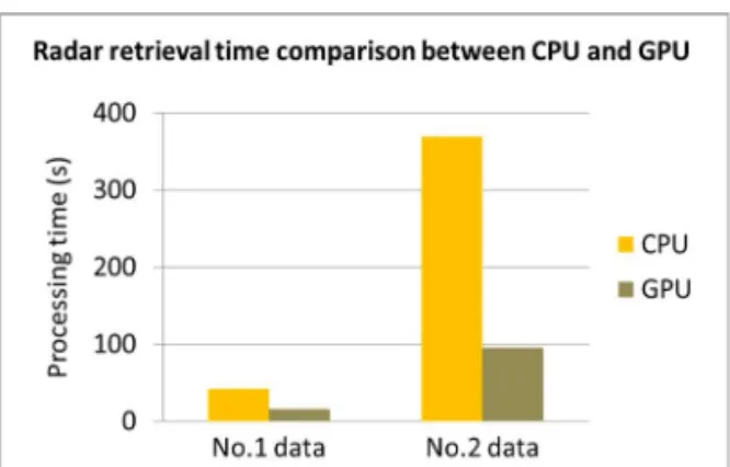
Fig. 11. Compare radar retrieval time base on CPU and GPU.
reduced, the whole performance of program would be much improved.
The interpolation step uses same function to calculate different data. Paper re-codes this part in CUDA program. In CUDA process, the inter- polation function is coded as the kernel; Kernel is the parallel processing function in CUDA. The par- allel process runs on two levels, the parallel be- tween blocks of grid and the parallel between threads of block. Data is processed on thread;
thread block is a number of threads which work together synergistically. Threads have the same lifetime in block, and all thread blocks have shared memory visible to each thread in the block. The number of threads in thread block is limited, but thread blocks which process a same kernel, and have same dimensionality and size can merge to a grid of thread block. Program can assign grids with arbitrary size of two-dimensional array. Then before running program, the parallel structure needs to be initially set. At that the kernel can be run on GPU. In radar interpolation case, Fig. 11 is the time comparison, from experiment results the processing time is reduced almost 4 times and with the image size increasing the speedup ratio is also increased.
In CDUA simulation, paper mainly applied to the radar image interpolation step, as the previous mentioned, because it is the most computationally expensive step. Actually several other steps can
also apply CUDA program. In data normalization and threshold step, paper normalized input gate values and classify to different color, this part con- tains logical operation. CUDA is not good at logical operation, but now GPU which has “1.1” compute capability[13] can process like “and, or, XOR”. And the GPU with more than “2.0” compute capability supports function pointer. It is much convenient for program. The rests can also be programed by GPU like coordinate transformation step. But computa- tion is not as complex as interpolation, because the latter has contained IDW (Inverse distance weighting), and a large amount of calculation times of operator. So paper only applied CUDA technol- ogy on data interpolation step. And for con- venience, paper used OpenCV for noise remove and radar image drawing etc.
5. CONCLUSIONS
This paper realized an interpolation method based on CUDA for fast weather radar data. Since the radar data file has a lot of data volume and many variables, weather radar retrieval and its in- terpolation processing are time consuming tasks, especially for dual polarization weather radars.
Then in the first step, paper simulated weather ra- dar imaging process by using "uf" radar file. next step, for improving processing speed, paper in- troduced CUDA program to calculate the dense parallel computation parts. The experiment showed performance by using CUDA platform in radar imaging processing. Paper briefly contains three parts for weather radar imaging: raw radar data reading, coordinate transformation and radar data interpolation. Through experiment in the past, peo- ple find that most of radar imaging time is spent on the third step, radar data interpolation. So paper introduced CUDA parallel programming into radar retrieval process, which is good at compute-in- tensive, highly parallel computation. With the help of CUDA’s parallel computing, weather radar
imaging time has been much reduced, as the paper experiment achieved the desired aims. The whole processing time is improved about 4 times. As the mentioned in paper, CUDA programming only ap- ply to the data interpolation step. Throughout the whole implementation process, several processing parts can also be calculated by using parallel mod- el, there is still room for improvement. The future work is that applies CUDA technique in more parts and optimizes the memory coalescing of GPU, the distribution of blocks and threads, for better performance.
REFERENCES
[ 1 ] J. G. Qiao, M. Song, and Y. Q. Wang, "Freeway Guidance System Design Based on Meteoro- logical information," International Conference on Future Computer Sciences and Application (ICFCSA), pp. 97-100, Jun. 2011.
[ 2 ] M. I. Skolnik,Introduction to Radar System, 3th ed. New Delhi, ND: McGraw-Hill, 2001.
[ 3 ] M. A. Richards,Fundamentals of Radar Signal P rocessing, New York, NY: McGraw-Hill, 2005.
[ 4 ] D. Flores-Tapia, G. Thomas, and S. Pistorius,
“A Comparison of Interpolation Methods for Breast Microwave Radar Imaging,” Engin- eering in Medicine and Biology Society, pp.
2735-2738, Sep. 2009.
[ 5 ] K. Shinozawa, M. Fujii, and N. Sonehara, “A Weather Radar Image Prediction Method in Local Parallel Computation,” IEEE World Congress on Computational Intelligence Neural Networks, Vol. 7, pp. 4210-4215, Jun. 1994.
[ 6 ] H. Y. Guo, J. P. Dai, and Y. F. Dai, “GPU Acceleration of Propeller MRI Using CUDA,”
Bioinformatics and Biomedical Engineering, pp. 1-4, Jun. 2009.
[ 7 ] S. L. Barnes, “Report on a Meeting to Establish a Common Doppler Radar Data Exchange Format,” The Bulletin of the American Metrological Society, Vol. 61, No. 11, pp. 1401- 1404, 1980.
[ 8 ] IRIS P rogrammer’s Manual, Vaisala Oyj, Inc., Helsinki, Finland, 2013.
[ 9 ] J. Zhang, H. Ken, W. W. Xia, and J. J. Gourley,
“Comparison of Objective Analysis Schemes for the WSR-88D Radar Data,” 31th Interna- tional Conference on Radar Meteorology, pp.
907-910, Aug. 2003.
[10] R. Kvasov, S. Cruz-Pol, J. Colom-Ustariz, L.
Leon Colon, and P. Rees, “Weather Radar Data Visualization Using First-Order Inter- polation,”IEEE International on Geoscience and Remote Sensing Symposium, pp. 3574- 3577, Jul. 2013.
[11] M. A. Askelson, J. P. Aubagnac, and J. M.
Straka, “An Adaptation of the Barnes Filter Applied to the Objective Analysis of Radar Data,” Monthly Weather Review, Vol. 128, No. 9, pp. 3050-3082, Sep. 2000.
[12] M. J. Thurley, S. Lulea, and V. Danell. “Fast Morphological Image Processing Open- Source Extensions for GPU Processing With CUDA,”IEEE Journal of Selected Topics in Signal P rocessing, Vol. 6, pp. 849-855, Jun.
2012.
[13] CDUA C programming Guide V6.0, NVIDIA Corporation, 2014.
[14] G. S. Song, Y. I. Yun, and W. H. Lee,
"Analysis on Digital Image Composite Using Interpolation," J ournal of Korea Multimedia Society, Vol. 13, No. 3, pp. 457-466, Mar. 2010.
Liu Yang
He received the B.S degrees in Software and Mechanical Engin- eering from Dalian Jiaotong University, China in 2010. He received the M.S degrees in IT Convergence and Application Engineering from Pukyong Na- tional University, Korea in 2012. He is currently a Ph.D. candidate in department of IT Convergence and Application engineering at the Pukyong National University. His research interests are in the area of digital image processing and radar retrieval.
Bong-Joo Jang
He received a B.S., a M.S., and Ph.D. degrees from Busan Uni- versity of Foreign Studies in 2002 and 2004, Pukyong Natio- nal University in 2013 re- spectively. He is currently re- searcher, Korea Institute of Civil Engineering and Building Technology. His research interests include multimedia signal processing/com- pression/security, radar signal processing and applica- tions.
Sanghun Lim
He received a B.S. degree in Electrical Engineering from Yonsei University in 1996 and a M.S., and Ph.D. degrees in Elec- trical & Computer Engineering from Colorado State University in 2002 and 2006, He worked re- search associate at CSU from 2006-2011 and research scientist at NOAA/CIRA in USA from 2011-2012. He is currently research fellow, Korea Institute of Civil Engineering and Building Technology. His research interests include radar meteorology/hydrology, radar system and signal processing.
Gi-Chang Kwon
Gi-Chang Kwon received a B.S., a M.S., and Ph.D. degrees from Andong National Univer- sity in 1985, Daegu Univsrsity in 1993, and Yeongnam Univer- sity in 2000. Currently, he is a professor in Department of IT Cooperative System at Geongbuk Provincial College.
His research interests include multimedia contents and image processing, digital contents and smart system.
Suk-Hwan Lee
He received a B.S., a M.S., and a Ph. D. degrees in Electrical Engineering from Kyungpook National University, Korea in 1999, 2001, and 2004 respec- tively. He is currently an asso- ciate professor in Department of Information Security at Tongmyong University. His research interests include multimedia security, digital image processing, and computer graphics.
Ki-Ryong Kwon
He received the B.S., M.S., and Ph.D. degrees in electronics en- gineering from Kyungpook Na- tional University in 1986, 1990, and 1994 respectively. He work- ed at Hyundai Motor Company from 1986-1988 and at Pusan University of Foreign Language from 1996-2006. He is currently a professor in Department of IT Convert- gence and Application Engineering at the Pukyong National University. He has researched University of Minnesota in USA on 2000~2002 with Post-Doc. and Colorado State University on 2011~2012 with visiting professor. He is currently the President of Korea Multimedia Society. His research interests are in the area of digital image processing, multimedia security and watermarking, bioinformatics, weather radar in- formation processing.