A B S T R A C T KEYWORDS Fire protection (sprinkler) piping system is an essential element for the energy supply
and for the protection against the seismic-induced fire during and after an earthquake.
The primary objective of this study was to understand the seismic performance of complex two-story piping system installed in a low-rise building subjected to bi-directional and three-directional earthquakes. The result of current study revealed that the displacement of the piping system in accordance with floor level was significantly different due to acceleration-sensitivity but the effect of the piping system due to the vertical direction earthquake was not significant.
Sprinkler Seismic Acceleration Fire Protection Piping system
화재방호계통 스프링클러 시스템의 경우 지진 발생 시 그리고 지진 발생 후에 유도되는 화 재로부터 건물과 인명을 보호하고 에너지를 공급을 위한 필수 요소라 할 수 있다. 본연구의 주목적은 양방향 (x, y) 그리고 3축(x, y, z)방향의 지진의 영향을 받는 저층 건물에 설치된 복층구조 스프링클러 파이프라인의 거동과 내진성능을 평가 하고자 함이다. 결과적으로 건 물의 비구조 요소인 스프링클러 파이프라인의 경우 각 층별로 다른 거동을 보이고 있으며, 또한 수직 방향의 지진의 경우 수평방향의 지진보다 파이프라인에 미치는 영향은 미미하다 고 볼 수 있다.
스프링클러 지진 가속도 화재방호 파이핑 시스템
ⓒ 2014 Koea Society of Diaster Information All rights reserved
화재방호계통 복층구조 스프링클러 파이프라인 내진성능 평가
Evaluation of Seismic Performance of 2-Story Fire Protection Sprinkler Piping System
Jun-Tai Jeon
a,1, Woo-Young Jung
b,2, Bu-Seog Ju
c,*a
Department of Civil & Environmental Engineering, INHA Technical Colege, InCheon, 402-752, Republic of Korea
b
Department of Civil Engineering, GangNeung-WonJu National University, GangNeung, 210-702, Republic of Korea
c
Department of Civil Engineering, North Carolina State University, Raleigh, NC27606, USA
* Corresponding author. Tel. 82-33-640-2416. Fax. 82-33-646-1391.
Email. [email protected]
1 Tel. 82-32-870-2235. Email. [email protected]
ARTICLE HISTORY
Recieved Jul. 28, 2014
Revised Jul. 31, 2014
1. Introduction
Fire suppression system such as sprinkler piping system, indoor fire hydrant, and automatic fire alarm systems in hospitals, emergency buildings, and high-tech facilities must remain operational/functional during and after the earthquake. Over the past decades, however, the damage was mainly caused by non-structural failure of critical facilities, rather than structural component failure. For example, the higher proportion of economic loss from Northridge Earthquake in 1994 was derived from the failure of non-structural component to non-residential buildings (Kircher, 2003). Furthermore, in the cases of Japan earthquake, the percentage of damaged fire protection (sprinkler) piping system during Kushiro-oki earthquake in 1993, Sanriku-haruka-oki earthquake in 1994, and Kobe earthquake in 1995 was 34%, 41%, and 40.8% (in Kobe city), respectively (Sekizawa et al., 2002). It revealed that the sprinkler piping system was the most vulnerable than other fire protection systems subjected to seismic ground motions.
In recent years, the studies in terms of functionality of the piping system were addressed, in order to understand its behavior and to apply the performance-based design approach based on reliability of the system. Antaki and Guzy (1998) identified the failure modes, stiffness, and first leakage points of threaded and grooved connections for the fire protection piping system based on National Fire Protection Association (NFPA-13) design guideline. As can be seen in previous studies, the failure modes of the piping system mainly occurred at connection points (T-joint and elbow) and supporting systems (unbracing hangers, bracing hangers, and anchors) during and after the earthquake. Therefore, the primary objective of this study was to understand and identify the seismic performance of the complex 2-story fire-protection (sprinkler) piping system installed in low-rise steel building system subjected to bi-directional and three-directional earthquakes.
2. Finite Element (FE) Model of Fire-Protection Piping System
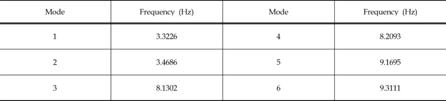
The 2-story piping system with assumed ceiling systems was made of 2-inch (branch piping system) and 4-inch black iron pipes (main piping system), as shown in Fig. 1. The sprinkler piping system was supported by unbraced hangers, transverse hangers, longitudinal hangers, and anchor systems in the main piping system. The piping system, using lumped mass and elastic beam column element was evaluated in Open System for Earthquake Engineering Simulation platform by Tck/Tk interpreter extension (OpenSees, 2011). The natural frequencies determined from eigenvalues and eigenvectors in OpenSees were given in Table 1. In addition, the first mode shape of 2-story piping system with the branch number was illustrated in Fig. 1.
Table 1. The Natural Frequency of the Sprinkler Piping System
Mode Frequency (Hz) Mode Frequency (Hz)
1 3.3226 4 8.2093
2 3.4686 5 9.1695
3 8.1302 6 9.3111
Level 5
Level 4 z
y
x
Fig. 1. FE odel of 2-story Fire Protection Piping System (FPPS)
3. Description of a Building Model and Seismic Ground Motions
Based on 5-story steel structure building model (Ju and Jung, 2013), the building model using a strong column and weak beam design philosophy was also conducted in OpenSees based on the structural FE method. The fundamental and second mode frequency was 2.589 (Hz) and 9.0643 (Hz), respectively. Also, mass participations of the first mode and second mode in the building system were 78.37% and 12.72%, respectively. It indicated that the total amount of the mass in the first two modes was over 90% (i.e., the first two modes of the building system subjected to a seismic ground motion were significantly important).
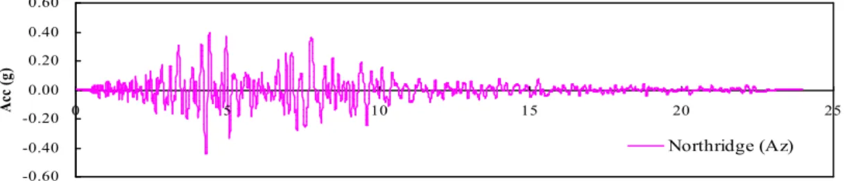
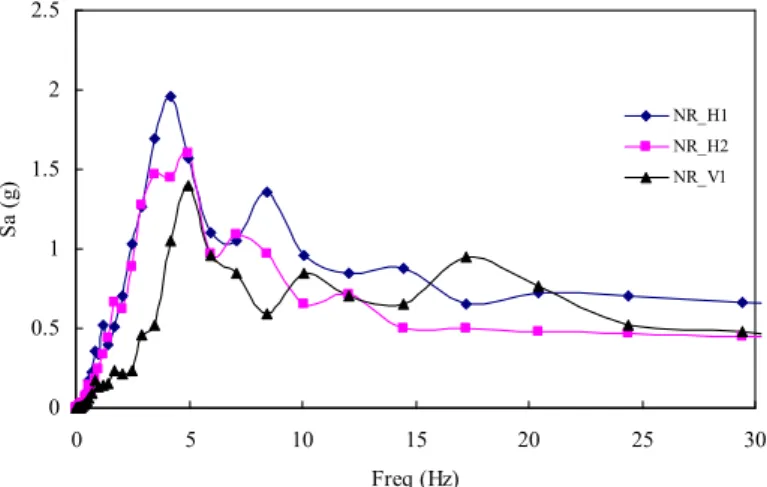
Fig. 2 showed the finite element model of the building system subjected to three-directional earthquakes (1994 Northridge earthquakes), obtained from PEER-NGA (PEER, 2013). The response spectra in terms of three-directional earthquakes with 5% damping ratio were also described in Fig. 3.
-0.80 -0.60 -0.40 -0.20 0.00 0.20 0.40 0.60
0 5 10 15 20 25
Time (sec)
Acc (g)
Northridge (Ax)
(a) Northridge Earthquake Acceleration Time History: Horizontal Direction (Ax)
-0.60 -0.40 -0.20 0.00 0.20 0.40 0.60
0 5 10 15 20 25
Ti me (se c)
Acc (g)
Northridge (Az)
(b) Northridge Earthquake Acceleration Time History: Horizontal Direction (Az)
-0.40 -0.30 -0.20 -0.10 0.00 0.10 0.20 0.30 0.40
0 5 10 15 20 25
Ti me (se c)
Acc (g)
Northridge (Ay)
(c) Northridge Earthquake Acceleration Time History: Vertical Direction (Ay)
(d) The Steel Moment Frame Building Model
Fig. 2. FE Model of the Building Model Subjected to Three-Directional Earthquakes
4. Seismic Analyses of the Fire-Protection Piping System
In order to evaluate the performance of the complex fire-protection (sprinkler) piping system, this study
considered two different earthquake scenarios: one with the building subjected to bi-directional seismic ground
motions (transverse and longitudinal horizontal directions); the other with the building under three-directional
earthquakes (two horizontal directions with a vertical direction). A classical damping in the 2-story piping system
and the building system was evaluated using mass and stiffness proportional Rayleigh damping equation. For the
analyses, 2% damping ratio was used for the steel structures such as the building and piping system and the
classical damping matrix considering Rayleigh damping was given by Eq. (1) (Chopra, 2001).
(1)
0 0.5 1 1.5 2 2.5
0 5 10 15 20 25 30
Freq (Hz)
Sa (g)
NR_H1 NR_H2 NR_V1
Fig. 3. Response spectra with 5% damping ratio
where, α was mass-proportional damping coefficient and β was stiffness-proportional damping coefficient. Based on FE models and the damping matrix, the procedure for seismic analyses was as follows:
Step 1: Select earthquake time histories from PEER and create the FE models of the structural and nonstructural systems.
Step 2: Perform dynamic analyses using multi-support excitation pattern to input bi-directional and three-directional earthquakes at each support of the structural systems in OpenSees and obtained linear displacement time histories at level 4 and level 5 corresponding to the multi-directional seismic ground motions.
Step 3: Apply linear displacement time histories to 2-story sprinkler piping system and analyze the maximum displacement at each point of the piping system.
Fig. 4(a) showed maximum displacements of each branch of the piping system at floor level 4 and 5 subjected to three-directional earthquakes. It was observed that most of the displacements in the piping system increased with increase of floor level. Fig. 4(b) illustrated the comparison of the seismic performance of the piping system on the top floor between bi-directional and three-directional earthquakes. It noted that the amplifications of the piping system were not significantly affected by the vertical excitation. Fig. 5 described the displacement histories at branch
#7 of the piping system. Moreover, the percentage of maximum displacement difference in accordance with the floor level was given in Table 2. According to the experimental test data from University at Buffalo (UB), State University of New York (Tian et al., 2010), the first leakage point at threaded T-joint of 2-inch black iron piping system was approximately 3.81 (cm) for a monotonic test and 1.27 (cm) for a cyclic test. Therefore, the results from numerical analyses noted that the displacement of the sprinkler piping system in terms of the maximum capacity was significantly exceeded and the functionality of the system can not be remained during and after an earthquake.
Table 2. The percentage of Maximum Displacement Difference
Branch No. Increment (%) Branch No. Increment (%)
1 3.4596 6 3.1443
2 0.2140 7 11.258
3 3.1292 8 3.7828
Fig. 4. Maximum Displacements of the Piping System in Terms of Levels and Earthquake Components
-15.00 -10.00 -5.00 0.00 5.00 10.00 15.00
0 5 10 15 20 25 30 35
Time (sec)
Disp (cm)