< 응 용 논 문 >
Copyright
Ⓒ2018 KSAE / 155-03 pISSN 1225-6382 / eISSN 2234-0149
DOI https://doi.org/10.7467/KSAE.2018.26.4.449Transactions of KSAE, Vol. 26, No. 4, pp.449-456 (July, 2018)
초소형 전기차를 이용한 개방형 자율주행 플랫폼 개발
이 호 원․기 석 철*
충북대학교 스마트카연구센터
Development of an Autonomous Driving Open Platform Using an Micro Electric Vehicle
Howon Lee․Seok-Cheol Kee*
Smart Car Research Center, Chungbuk National University, Chungbuk 28644, Korea (Received 26 January 2018 / Revised 19 March 2018 / Accepted 29 March 2018)
Abstract : Future automobiles are being developed with the fusion of autonomous driving technology and environ- mentally friendly electric vehicles. For an autonomous vehicle to successfully drive on its own, it is necessary for the vehicle to create a driving path and recognize the surrounding environment by using sensor information, such as LiDAR, GPS, and camera, and to ensure that the vehicle is able to travel safely to its target point. In this paper, we have developed a hardware platform that can run autonomously by using a micro electric vehicle, and we have installed a VCU to control the vehicle. By releasing the CAN interface information from the developed micro electric vehicle-based autonomous driving platform, we are able to share intelligent vehicle development methods and propose them as research reference.
Key words : Open platform(개방형 플랫폼), Lidar(라이다), Vision sensor(비전센서), GPS(위성항법 시스템), VCU(차량 제어 장치), Autonomous vehicle(자율주행 자동차), Electric vehicle(전기자동차)
1. 서 론1)
자율주행 자동차에 대한 연구개발은 운전자의 편 의성을 극대화 할 수 있는 지능형 자동차 기술로 발 전하고 있다. 이에 따라 최근 전세계적으로 많은 국 가 및 글로벌 기업들이 무인자동차에 대한 연구를 활발히 진행하고 있다.1-3)
또한 탄소배출에 따른 대기 오염에 대한 환경 규 제가 강화되어가고 있고, 이에 따라 친환경 차인 전 기차에 대한 관심이 높아지고 있는 추세이다.
현재 대도시의 많은 근로자가 개인용 차량을 이
용하고 있고, 이 중에서 80 %는 100 km 이내의 근거 리를 이동한다. 개인용 차량은 대부분 1~2인이 탑승 하고 있고, 도심의 유동인구 및 차량의 증가로 교통 혼잡이 증대되고, 주차장 효율성을 획기적으로 향 상 시키는 새로운 이동수단의 필요성이 제기 된다.
이에 따라 1~2인승용 초소형 전기자동차 또한 국 내외 여러 기업들에 의해 개발 및 출시가 진행되고 있다. 초소형 전기차는 일반 전기자동차에 비해 충 전시간이 짧고, 유지 비용 또한 낮아 최근 대중의 관 심이 더욱 높아지고 있다.4-9)
*
A part of this paper was presented at the KSAE 2017 Fall Conference and Exhibition
*
Corresponding author, E-mail: [email protected]
* This is an Open-Access article distributed under the terms of the Creative Commons Attribution Non-Commercial License(http://creativecommons.
org/licenses/by-nc/3.0) which permits unrestricted non-commercial use, distribution, and reproduction in any medium provided the original work is properly cited.
이호원․기석철
본 논문에서는 대창모터스에서 개발한 초소형 전기차 다니고를 이용하여, 자율주행이 가능한 플 랫폼으로 개조 및 개발을 진행하였다. 상용 초소형 전기자동차에 자율주행에 필요한 환경 인지 및 위 치인식을 위한 여러 센서들을 장착하였고, 차량내 의 여러 ECU(Electronic control unit)를 제어하기 위 한 VCU(Vehicle Control Unit)를 장착하였다. 본 논 문은 2장에서 연구개발에 사용된 초소형 전기차에 대한 소개와 구성, 3장은 주행환경 인지를 위한 센 서구성, 4장은 자율주행 플랫폼 전체 전장 구성, VCU 정보 및 CAN ID 구성에 대한 내용을 담고 있 다. 5장에서는 하드웨어 검증 및 기본적인 자율주 행 테스트를 진행하였고, 이를 통해 구성 된 자율주 행 플랫폼의 CAN 통신 정보 완전 공개하여 개방형 플랫폼 형태의 자율주행 연구용 참조 차량을 제공 하고자 한다.
2. 초소형 전기차(다니고)
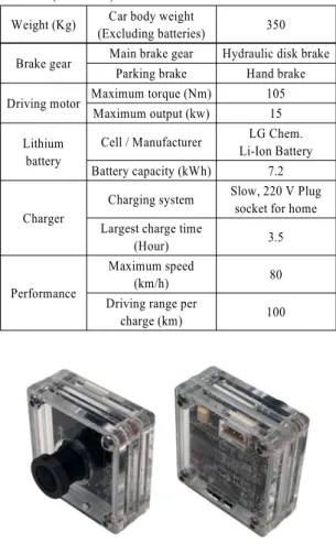
자율주행자동차에 사용된 초소형 전기차 다니고 는 배터리를 포함한 총 중량 450 kg 및 1충전 최대 주행거리 100 km, 최고 속도 80 km/h를 가진 2인승 차량이다. 초소형 전기차 다니고는 국토교통부로부 터 유럽 자동차 안전 기준 ‘L7(초소형 전기차)’평가 를 통과하였고, 국내 도로 주행 자격을 갖춘 차량이 다. 초소형 전기차 다니고의 상세 스팩은 아래 Table 1, 2와 같다.10)
3. 자율주행차 센서 구성
자율주행차량이 주행에 필요한 외부 환경 인지 및 위치 인식을 위하여 차량 내, 외부에 각종 센서들 을 장착하였다. 장착 된 센서들을 이용하여 차선 인 식, 장애물 인식, 차량의 위치 및 자세 정보, 주행 경 로 등을 파악할 수 있다.
3.1 비전 센서
자율주행차에 장착된 비전센서(카메라)는 차선, 장애물, 신호등을 인식하기 위해 사용된다. 본 자율 주행차량에 사용된 비전센서는 Fig. 1과 같은 위드 로봇 회사의 oCam–1CGN–U를 사용하였다.
oCam-1CGN-U는 OnSemi AR0134 CMOS image
Table 1 Dimensions of micro electric vehicle (DANIGO)
Full lenght (mm) 2300
Full width (mm) 119
Full height (mm) 1485
Axial gap (mm) 1715
Wheel span (mm) 1000
Table 2 Technical specifications of micro electric vehicle (DANIGO)
Weight (Kg) Car body weight
(Excluding batteries) 350 Brake gear Main brake gear Hydraulic disk brake
Parking brake Hand brake Driving motor Maximum torque (Nm) 105
Maximum output (kw) 15 Lithium
battery
Cell / Manufacturer LG Chem.
Li-Ion Battery Battery capacity (kWh) 7.2
Charger
Charging system Slow, 220 V Plug socket for home Largest charge time
(Hour) 3.5
Performance
Maximum speed
(km/h) 80
Driving range per
charge (km) 100
Fig. 1 Vision sensor (oCam-1CGN-U)
sensor, 표준 M12렌즈를 사용하고 있다. 내부 카메라 제어로 Gain, White Balance Blue, White Balance Red, Exposure 등을 지원한다. 윈도우7/8/10 및 Linux를 모 두 지원하고 있어 다양한 환경에서 사용이 용이하다.
또한 다용도의 비젼 처리에 적합한 1 메가픽셀의 글로벌 셔터 컬러 카메라로 USB 3.0을 통해 고속전 송이 가능하며 UVC 호환으로 특별한 드라이버를 설치하지 않고 폭넓은 사용 환경에서 사용될 수 있다.
초소형 전기차를 이용한 개방형 자율주행 플랫폼 개발
3.2 Lidar
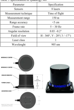
Quanergy M8 LiDAR 센서는 5~30 Hz의 속도로 회 전 할 수 있는 8채널의 2D라인 스캐너로 구성되어 있다. 8채널의 레이저는 20도의 Field of view(FOV) 를 가지며 전체 장치는 360도의 회전을 한다. 센서 를 사용 가능하게 하기 위해 ROS기반의 대이터 기 록 SDK와 응용 프로그램을 제공한다. M8의 사양은 Table 3에 나오며, 사진은 Fig. 2에서 확인할 수 있다.
Table 3 Specification of Quanergy M8
Parameter Specification
Sensors 8 lasers
Measurement technique Time of flight
Measurement range 150 m
Range accuracy <5 cm
Frame rate 5 ~ 30 Hz
Angular resolution 0.03 ~0.2°
Field of view H : 360°, V : 20°( 3 / -17°)
Laser class 1
Wavelenght 905 nm
Fig. 2 Quanergy M8 LiDAR
3.3 GPS (Global Positioning System)
차량의 위치정보를 획득하기 위한 GPS모듈은 Ublox사의 C94-M8P를 사용하였다. C94-M8P는 Rover와 Base Station의 개념을 RTK 기술을 사용하 여 구성하도록 하였다. Base Station로부터 데이터 스트림을 사용함으로써, Rover는 차량에서 사용 가 능한 높은 수준의 정확도로 상대 위치를 출력할 수 있다.
3.4 IMU (Inertial Measurement Unit)
자율주행차의 자세변화 및 주행정보를 위한 IMU 센서는 NTREX사의 NT-ARSv2를 사용하였다. NT- ARSv2 3축 가속도센서와 2축 자이로센서 데이터를 사용하여 6개의 위치와 자세정보(x, y, z, roll, pitch, yaw)중 Roll과 Pitch각을 구하는 ARS(Attitude Refer- ence System)모듈이다. NT-ARSv2는 RS-232와 CAN 통신 인터페이스를 지원한다. 자세한 스펙은 Table 4에서 확인할 수 있다.
Table 4 Electric specification of NT-ARSv2
Parameter Max range
Supply voltage 4.5~10 V
Gyroscope range ∓500 degree/s
Accelerometer range ∓1.5 g
Bootint time 50 ms
Initialization time 100 ms
Interface RS-232 / CAN2.0B
4. 자율주행 전기차 플랫폼 및 VCU 4.1 자율주행 전기차 플랫폼
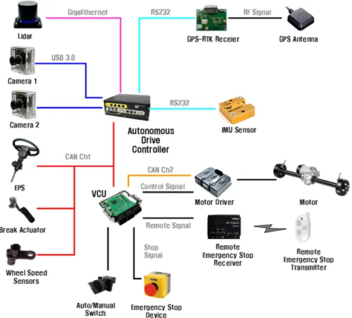
3장에서 소개한 주행환경 인지를 위한 센서 및 차 량의 제어 및 주행에 필요한 VCU를 탑재하여 자율 주행이 가능하도록 차량 전장을 구성하였다. 차량 의 주행에 필요한 3가지 모드(Auto, Manual, Reset) 설정 스위치가 있고, 자율주행모드 중에 발생하는 돌발상황에 대비하기 위한 차량내・외부에비상정지 장치 및 원격비상정지 수신기가 장착되어있다. 초 소형 전기자동차 자율주행 플랫폼 전장구성은 Fig. 3 에서 볼 수 있다.
자율주행제어기는 센서로부터 획득한 주행환경 정보를 이용하여, 자율주행 경로 계획을 수립하게 된 다. 이를 통해 자율주행 제어기는 VCU, EPS(Electronic Power Steering), Break Actuator 등으로 CAN 통신을 통해 제어를 할 수 있다.
Fig. 4는 개발된 초소형 전기차를 이용한 개방형 자율주행 플랫폼이다. 제안하는 자율주행 플랫폼은 산업부가 지원하는 2017년 대학생 자율주행 경진대 회에 참가한 8개 대학에 지원되어 구현된 성능을 모 두 검증하였다.
Howon Lee․Seok-Cheol Kee
Fig. 3 Configuration of proposed autonomous driving platform
Fig. 4 Autonomous driving open platform
4.2 VCU
VCU는 자율주행을 위한 초소형 전기차 차량 내 ECU 및 각종 장치들을 인터페이스 하는 차량제어 장치로 상위제어기(자율주행제어기)로부터 CAN
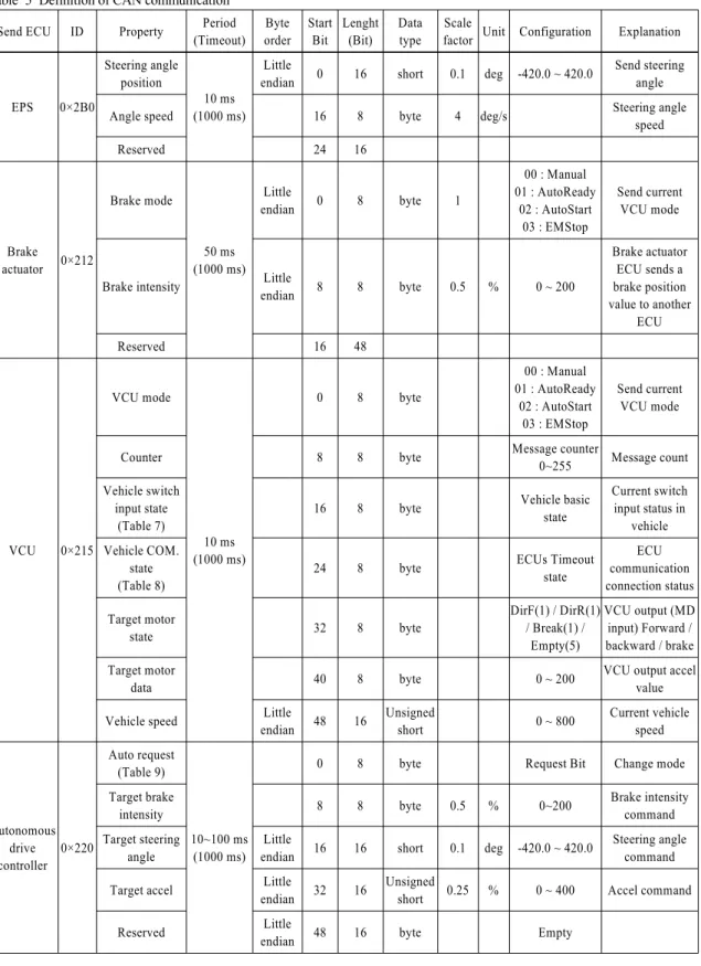
통신을 통해 제어 명령을 받아 차량내 장치들을 제 어하는 Unit이다. 자율주행 초소형 전기차 플랫폼의 CAN ID 구성은 Table 5와 같다.
탑재 된 VCU는 2개의 모드를 가지고 있다. 첫 번 째로 수동모드는 기존 차량들과 동일하게 사람이 운전 가능하도록 한 제어 모드이다. 두 번째로 자동 모드는 VCU가 자율주행장치로부터 CAN통신을 통 해 명령을 받아 주행하는 모드이다. 자동모드는 3개 의 State(Auto Start State, Auto Ready State, Emergency Stop State)로 구성되어 있다. Table 6은 VCU 모드 및 State에 대한 상세표이고, Fig. 5는 자동모드의 State 전환 상태를 보여준다.
VCU의 CAN message 16~23 bit 값을 통해 자율 주행 제어기에서는 현재 VCU의 스위치 입력 상태 를 확인 할 수 있다. Table 7은 현재 차량 내 스위치 입력 상태에 따른 Vehicle Basic State 값에 대한 것 이다.
Development of an Autonomous Driving Open Platform Using an Micro Electric Vehicle
Table 5 Definition of CAN communication Send ECU ID Property Period
(Timeout) Byte order
Start Bit
Lenght (Bit)
Data type
Scale
factor Unit Configuration Explanation
EPS 0×2B0
Steering angle position
10 ms (1000 ms)
Little
endian 0 16 short 0.1 deg -420.0 ~ 420.0 Send steering angle
Angle speed 16 8 byte 4 deg/s Steering angle
speed
Reserved 24 16
Brake actuator 0×212
Brake mode
50 ms (1000 ms)
Little
endian 0 8 byte 1
00 : Manual 01 : AutoReady
02 : AutoStart 03 : EMStop
Send current VCU mode
Brake intensity Little
endian 8 8 byte 0.5 % 0 ~ 200
Brake actuator ECU sends a brake position value to another
ECU
Reserved 16 48
VCU 0×215
VCU mode
10 ms (1000 ms)
0 8 byte
00 : Manual 01 : AutoReady
02 : AutoStart 03 : EMStop
Send current VCU mode
Counter 8 8 byte Message counter
0~255 Message count Vehicle switch
input state (Table 7)
16 8 byte Vehicle basic
state
Current switch input status in
vehicle Vehicle COM.
state (Table 8)
24 8 byte ECUs Timeout
state
ECU communication connection status Target motor
state 32 8 byte
DirF(1) / DirR(1) / Break(1) /
Empty(5)
VCU output (MD input) Forward / backward / brake Target motor
data 40 8 byte 0 ~ 200 VCU output accel
value
Vehicle speed Little
endian 48 16 Unsigned
short 0 ~ 800 Current vehicle
speed
Autonomous drive controller
0×220
Auto request (Table 9)
10~100 ms (1000 ms)
0 8 byte Request Bit Change mode
Target brake
intensity 8 8 byte 0.5 % 0~200 Brake intensity
command Target steering
angle
Little
endian 16 16 short 0.1 deg -420.0 ~ 420.0 Steering angle command
Target accel Little
endian 32 16 Unsigned
short 0.25 % 0 ~ 400 Accel command
Reserved Little
endian 48 16 byte Empty
이호원․기석철
Table 6 Description of the mode and state of VCU
Mode
Manual Personal driving
Auto
Auto ready state
- Vehicle is stop state
- Switch to auto start state by receiving auto start command from autonomous drive controller Auto start
state - Vehicle is driven by receiving a control command from the autonomous drive controller Emergency
stop state
- Vehicle is in the auto start state or auto ready state, the stop signal is received via the emergency stop button(or stop remote control)
- Can be reset via reset-switch or command from the autonomous drive controller - When reset, it changes to auto ready state
Fig. 5 Witching states of auto mode Table 7 Vehicle basic state
Vehicle basic state Status Explanation
Vehicle input state
16 Manual/Auto switch state
0 : Auto 1 : Manual
Auto / Manual switch status 17 Emergency
stop switch
0 :Off 1 : On
EM switch status 18 Emergency
reset switch
0 :Off 1 : On
EM reset switch status 19 Remote stop 0 :Off
1 : On
Remote stop input status 20 Remote pause 0 :Off
1 : On
Remote pause input status 21 Remote start 0 :Off
1 : On
Remote start input status 22 External in 0 External input 0 23 External in 1 External input 1
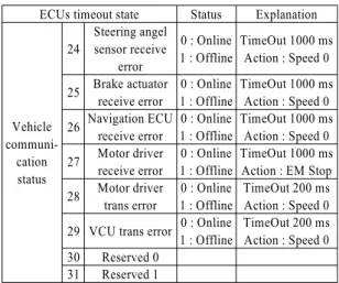
또한 VCU의 24~31 bit는 ECUs TimeOut State로 ECU의 통신연결 상태를 나타낸다. TimeOut State는 Table 8에서 볼 수 있다.
Table 8 ECUs timeout state
ECUs timeout state Status Explanation
Vehicle communi-
cation status
24
Steering angel sensor receive
error
0 : Online 1 : Offline
TimeOut 1000 ms Action : Speed 0 25 Brake actuator
receive error
0 : Online 1 : Offline
TimeOut 1000 ms Action : Speed 0 26 Navigation ECU
receive error
0 : Online 1 : Offline
TimeOut 1000 ms Action : Speed 0 27 Motor driver
receive error
0 : Online 1 : Offline
TimeOut 1000 ms Action : EM Stop 28 Motor driver
trans error
0 : Online 1 : Offline
TimeOut 200 ms Action : Speed 0 29 VCU trans error 0 : Online
1 : Offline
TimeOut 200 ms Action : Speed 0 30 Reserved 0
31 Reserved 1
마지막으로 자율주행제어기는 CAN message (CAN ID : 0x220) Request Bit(0~7 bit)를 통해 VCU의 모드 변경 메시지를 전송하게 되는데 해당 Request Bit의 내용은 Table 9에서 볼 수 있다.
Table 9 Request bit
Request bit Status Explanation
Vehicle request
0 Auto start
request 1:Request -
1 Auto ready
request 2:Request -
2 EM stop
request 3:Request -
3 EM reset
request 4:Request -
4
Moving direction FWD
0: Set
1: Reset F:0, B:0 → Stop F:0, B:1 → Forward F:1, B:0 → Backward
F:1, B:1 → Stop 5
Moving direction BWD
0: Set 1: Reset 6 Reserved 0
7 Reserved 1
초소형 전기차를 이용한 개방형 자율주행 플랫폼 개발
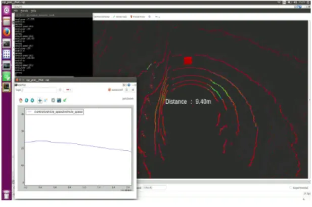
5. 센서 융합 및 주행 제어 실험 본 논문에서 제안된 초소형 전기차를 이용한 개 방형 자율주행 플랫폼은 2017년 산업부 대학생 자 율주행차 경진대회의 공식 플랫폼으로 제공 되었으 며, 제공되는 차량에 대한 하드웨어 검증을 위해 완 성된 차에 대한 기본적인 실험을 충북대학교 오창 자율주행차 성능시험장 및 대구 지능형자동차부품 진흥원 주행시험장에서 진행하였다. 실험에 사용된 자율주행 제어기는 노트북(Intel i7-6700HQ CPU @ 2.6GHz, RAM 16GB)으로 각종 센서로 부터 들어오 는 데이터를 바탕으로 ROS 환경에서 센서 융합 및 주행알고리즘을 수행하였다. Fig. 6~8은 장애물 인 식, 협로주행, 전방 차량 인식 및 AEB(Autonomous Emergency Brake), ACC(Adaptive Cruise Control) 주 행에 대한 결과이다. 장애물 인식은 성능 평가를 위 해 총 길이 430 m 길이의 도로에 80개의 장애물을 설치하여 진행하였다. 협로주행은 총 길이 50 m의 구간에 150개의 장애물을 S자 형태로 설치하였다.
AEB 및 ACC 테스트를 위해 실험자와 차량의 안전 을 위하여 차량모형물을 설치하여 진행하였다.
Table 10은 실험 결과에 대한 측정치이다.
Fig. 6 Obstacle avoidance
Fig. 7 Narrow-road driving
Fig. 8 AEB & ACC
Table 10 Experiment result
Evaluation list Measured value Maximum autonomous speed 40 kph Autonomous emergency brake 20 kph Object recognition rate 100 %
6. 결 론
초소형 전기차 다니고를 이용하여 LiDAR, Camera, GPS, IMU 센서와 긴급정지 등의 안전장치 등으로 전장을 구성하였고, 여러 ECU들을 제어하기 위한 VCU를 장착하여 개방형 자율주행 플랫폼 개발을 수행하였다. 개발된 초소형 전기차 기반의 개방형 자율주행 플랫폼에 대한 기본적인 센서 및 주행 테 스트를 수행하여 하드웨어 검증을 하였다. 그리고 이 자율주행 플랫폼을 2017년 대학생 자율주행경 진대회에 참가한 8팀에 대회용 플랫폼으로 제공하 였다.
본 초소형 전기차 기반 개방형 자율주행 플랫폼 을 이용하여 누구나 센서를 위한 인지 알고리즘 및 차량 제어 알고리즘을 통해 자율주행차 연구개발을 진행할 수 있을 것으로 기대된다.
후 기
이 논문은 2016년도 정부(과학기술정보통신부) 의 재원으로 정보통신기술진행센터의 지원을 받아 수행된 연구임(No. R7117-16-0164, (광역주행-총괄 /1세부) 차량 통신 기반의 광역 주행환경인지 및 협 조 주행기술 개발).
Howon Lee․Seok-Cheol Kee
References
1) H. Lee, D. Lee, H. Yoon, I. Song, K. Yun and S. Kee, “Development of Compact Electric Vehicle Platform for Autonomous Driving,”
KSAE Fall Conference Proceedings, pp.763- 768, 2017.
2) H. Kim, M. Heo, S. Han, S. Lee and J. Lee, “A Study on Recognition Algorithm for Unmanned Autonomous Vehicle,” KSAE Fall Conference Proceedings, pp.790-791, 2017.
3) J. Kim, J. Min, K. Kwak and K. Bae, “Travers- able Region Detection Based on a Lateral Slope Feature for Autonomous Driving of UGVs,”
Journal of Institute of Control Robotics and Systems, Vol.23, No.2, pp.67-75, 2017.
4) I. Kim, K. Yang, J. Yun and S. Hwang, “Deve- lopment of Path Plan Algorithm and Electric Vehicle Platform for Autonomous Driving,”
KSAE Annual Conference Proceedings, pp.1772- 1775, 2013.
5) Y. Son, “The Necessity of Electric Cars in Korea and Status of Technology Development,” The
Magazine of the IEEE, Vol.42, No.9, pp.29-37, 2015.
6) S. Yang, N. Jeong, K. Kim, S. Choi, W. Maosen, H. Kim and M. Suh, “Development of Urban Driving Cycle for Performance Evaluation of Electric Vehicles Part I : Development of Driving Cycle,” Transactions of KSAE, Vol.22, No.7, pp.117-126, 2014.
7) T. Lee, S. Kim and Y. Ko, “A Study on the Control Algorithm of VCU for Micro-mobility,”
Transactions of KSAE, Vol.26, No.1, pp.32-41, 2018.
8) J. Kim, “Utilization and Prospect of Micro Electric Vehicle for Delivery and Mail Deli- very,” Monthly KOTI Magazine on Transport, Vol.238, pp.42-46, 2017.
9) C. Park, “Technology Trends and Developments in Micro Electric Vehicle,” The Korean Ins- titute of Electrical Engineers, Vol.66, No.7, pp.21-26, 2017.
10) DaeChang Motors, Micro Eletronic Car, www.dacmotors.co.kr/product/smart-car, 2018.