Vol. 16, No. 4 pp. 2770-2776, 2015
Analysis and fabrication of a wearable antenna using conductive fibers
Tien Manh Nguyen
1and Jae-Young Chung
1*1Dept. of Electrical and Information Engineering, Seoul Nat'l Univ. of Science and Technology
전도성 실 재질을 이용한 웨어러블 안테나의 제작 및 분석
티엔만1, 정재영1*
1서울과학기술학교 전기정보공학과
Abstract The development of efficient wearable antennas is required to implement short range body-centric wireless communication links for various internet of thing applications. We present simulation and measurement results of conductive-fiber-based wearable antennas which can comfortably fabricated directly on usual clothing materials. The proposed antenna is a form of a rectangular patch antenna designed by weaving conductive fibers on a felt substrate.
A full-wave electromagnetic simulation tool is used to investigate the antenna performance such as antenna impedance, resonant frequency, and radiation efficiency. Parametric studies show that the radiation efficiency increases from 67.5% to 70.4% by widening the gap between conductive fibers from 0.25mm to 3mm. This implies a wearable antenna with good radiation efficiency can be designed despite of less portion of conductive fibers on the antenna.
The simulation results are also verified by measured results with fabricated antennas.
요 약 최근 인체 중심의 근거리, 저전력 무선통신을 이용한 다양한 사물인터넷 어플리케이션이 출현함에 따라 효율적으로 무선에너지를 방사시킬 수 있는 소형 웨어러블 안테나 개발의 필요성이 대두되고 있다. 본 논문에서는 전도성 실로 일상 의류에 간편하게 구현할 수 있는 웨어러블 안테나의 특성을 시물레이션 및 측정 결과를 바탕으로 분석하였다. 제안한 안테나 는 펠트 천 위에 전도성 실을 직교로 엮은 형태로 구현하였으며 full-wave 전파 시물레이션 툴을 이용한 parametric study를 바탕으로 구조 변화에 따른 안테나 임피던스, 공진 주파수 및 방사 효율 등의 변화를 관찰하였다. 그 결과, 안테나 방사효율이 전도성 실 사이 간격이 0.25mm에서 3mm로 증가함에 따라 67.5%에서 70.4%로 증가함을 확인하였다. 이를 통해 적은 양의 전도성 실 재질을 이용해도 좋은 방사효율의 안테나를 구현할 수 있다는 결론을 도출할 수 있다. 실제 제작된 안테나를 통해 구한 측정값도 유사한 경향을 보였다.
Key Words : Antenna, conductive fiber, radiation efficiency, wearable antenna.
This study was supported by the research program funded by the Seoul National University of Science and Technology.
*Corresponding Author: Jae-Young Chung (Seoul National Univ. of Science and Technology) Tel: +82-2-970-6445, email: [email protected]
Received January 14, 2015 Accepted April 9, 2015
Revised February 27, 2015 Published April 30, 2015
1. Introduction
Wearable electronics have gained a onsiderable attention both in academia and industry due to their potential for enabling seamless body-centric communication over a wireless link. It was forecasted that global shipments of wearable devices would reach
1.5 billion and related sales of more than 58 billion USD in 2018 [1]. Currently, many of them are released in the type of gadget such as watches and glasses, however, by 2030, the whole system is expected to be integrated on clothes (or on human body).
In this context, the development of wearable antennas is important to establish reliable wireless
communications over the air. Wearable antennas are required to be light-weight, low cost, and highly integrable on clothes with a good antenna radiation efficiency. Conductive fibers, or the so called e-fibers, are highlighted as a promising material to fulfill the above requirements. They consists of polymer core and metal coat offering high flexibility and conductivity in the order of to Siemens/m. Furthermore, an ordinary sewing machine can e used to integrate them on a fabric substrate such as felt, fleece, and silk without significant effort. A vast amount of wearable antenna designs with various e-fibers has been reported in the past few years [2-7].
We investigate the antenna characteristics of a conductive-fiber-based antenna based on simulation and measurement results. simulation and measurement results. A rectangular patch antenna is designed by weaving conductive fibers in a orthogonal manner. A commercial electromagnetic simulation tool, Ansys HFSS [8], is used to model the antenna structure. This tool offers convenient CAD user interface and accurate full-wave simulation results based on finite element methods (FEM). With the simulation model, the antenna figures of merit such as resonant frequency, impedance, and radiation efficiency, are observed by changing geometrical parameters. In particular, the gap between the fibers is the main concerns.
Parametric studies show that the radiation efficiency increases a wider gap between conductive fibers, implying a wearable antenna with good radiation efficiency can be designed despite of less portion of conductive fibers on the antenna. This result is also verified by measured results with fabricated antennas.
2. Antenna Design
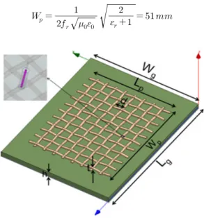
Fig. 1 illustrates the patch antenna with conductive fibers for the simulation study. The antenna is designed to resonate at GHz. The substrate is considered as a felt fabric with the thickness of
mm, dielectric constant of , and loss
tangent of . The conductive fiber emulates the one provided by Syscom Advanced Materials (LiberatorTM) [9]. This fiber consists of a bundle of silver coated threads with an overall diameter of 0.3 mm and line resistance of 1.0 Ohm/foot.
Based on the above material parameters, the dimensions of the antenna are carried out by the formulas for patch antenna design found in elsewhere [10]. More specifically, the width of the patch () and ground () are obtained by:
Fig. 1. Simulation model of conductive fiber antenna
In order to calculate the length of the patch () and ground (), the effective dielectric constant () and length extension () due to the fringing effect must be obtained first. They can be calculated by:
Finally, and are obtained by:
The final design parameters are listed in Table 1.
They are all the same to the description above except for reduced down from 43.3 mm to 40 mm, which is due to the difference between the woven patch and ideal metal patch. The formulas used assume the patch is made of a perfect electric conductor (PEC). On the other hand, the woven patch is not homogeneous and its conductivity is lower than ordinary metals. Owing to this discrepancy, is adjusted to 40 mm to keep the antenna resonate at 2.4 GHz.
Parameter Value
61.6 mm
53 mm
51 mm
40 mm
1.6 mm
Table 1. Antenna dimensional parameters
The antenna is fed by a 50 ohm coaxial cable as in the inset of Fig. 1. The tip of the inner conductor of the coaxial cable is immersed in the interlacing fibers.
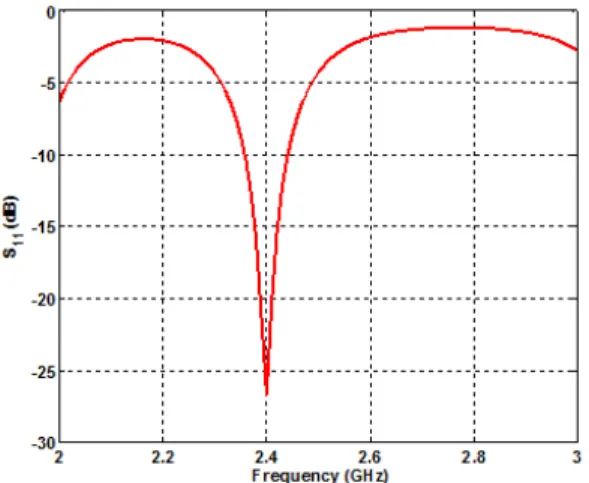
Fig. 2. Simulation result of antenna reflection coefficient with d = 0.5 mm
Fig. 3. Simulation result of antenna radiation efficiency with d = 0.5 mm
Fig. 4. Antenna resonance frequency versus gap size
Fig. 5. Antenna radiation efficiency versus gap size
The simulated reflection coefficient () and radiation efficiency of the designed antenna are depicted in Fig. 2 and 3 , respectively. 4. As can be seen, the antenna resonates at 2.4 GHz with fractional bandwidth of 80 MHz (i.e. ←dB from 2.36 to 2.44 GHz). The radiation efficiency just reaches 50%
at the resonant frequency due to the relatively higher loss tangent of the substrate and lower conductivity of the fibers compared to conventional patch antennas.
3. Parametric Study of Gap Size
In this section, the antenna characteristics of the conductive fiber-based antenna is investigated by changing the gap size between the fibers (d in Fig. 1).
The dimensions of the patch and ground are the same with the previous section, while d varies from 0.5 mm to 2 mm with the interval of 0.25mm.
Fig. 4 shows the change in the antenna resonant frequencies by varying d. The resonant frequency does not linearly increase as the gap increases or, in other words, as the portion of metal decreases. It may due to the fixed size of the overall patch size. Also, the fundamental electromagnetic mode around the patch may not see the gap as it is relatively short compared to the operating wavelength.
Fig.5 shows the antenna radiation efficiency with different gap sizes. These values are taken at the resonance frequencies of the antenna for each gap size.
The linear increase of the radiation efficiency from 50
% to 53.4 % is observed when the gap size is longer than 1 mm. This is an interesting feature which is opposite to the previously reported results with meshed patch antennas [11-12]. Although the conductive materials are different (e.g. thin copper or carbon nanotube thread), the radiation efficiency of the meshed patch antennas increases as the patch includes more portion of conductive materials. On the contrary, this work demonstrates that the antenna with larger spacing and less conductive fibers exhibits the higher radiation efficiency.
Fig. 6. Antenna resistance versus gap size
In an attempt to examine further, we calculate the antenna radiation resistance () and loss resistance () from the radiation efficiency at the frequency where the antenna reactance is zero, implying no stored energy retained in the antenna. It is observed in Fig.
6 that and both fluctuate with different gap sizes but the difference between them becomes larger as the gap size increases (the shaded region). The improvement of the radiation efficiency may originate from the predominating over in the course of gap increase. As in Fig. 6, the ratio between radiation resistance and loss resistance, , has a continual rise. The surface current distribution depicted in Fig. 7 also displays that the currents with large magnitude is more concentrated on the patch edges when the gap is wider.
(a) (b)
Fig. 7. Surface current distribution (a) d = 0.5 mm (b) d = 2.0 mm
4. Antenna Fabrication and Measurement
The conductive fiber-based antenna was fabricated over a felt substrate using silver-coated fibers (LiberatorTM). Fig. 8(a) and (b) are picture of the fabricated antennas with d = 0.25 and 3 mm, respectively. The orthogonally woven patch was disposed on a felt substrate and fed by a coaxial probe using conductive silver epoxy.
(a) (b)
Fig. 8. Pictures of fabricated antennas (a) d = 0.25 mm, (b) d = 3 mm
(a) d = 0.25 mm
(b) d = 3 mm
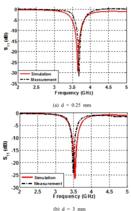
Fig. 9. Reflection coefficient of simulation and measurement results with different d
The responses of the antennas were measured by a network analyzer (Anritsu MS2038C). They were compared to the simulation results, as shown in Fig. 9, where (a) and (b) correspond to the antenna with d = 0.25 mm and 3 mm. As observed, the measurement and simulation showed good agreement. For instance, the resonant frequencies of measurement and simulation are 3.68 and 3.65 GHz in Fig. 9(a), while those are 3.5 and 3.53GHz in Fig. 9(b).
(a) E-plane, d = 0.25 (b) H-plane, d = 0.25
(c) E-plane, d = 3 (d) H-plane, d = 3 Fig. 10. Reflection coefficient of simulation and
measurement results with different t and d
The antenna’s radiation pattern and efficiency were measured in an anechoic chamber. Fig. 10 shows the E- and H-plane radiation patterns. They exhibit a typical broadside radiation pattern of a patch antenna backed by a ground plane. The measured results agree well with the simulation results except for a slight asymmetry in the H-plane patterns. This may be caused by the asymmetry of the patch edge during the fabrication process. The broadside gain values are 5.9 to 7.5 dBi.
d = 0.25 mm d = 3 mm
Simulation 67.5 % 70.4 %
Measurement 78.5 % 80.8 %
Table 2. Antenna radiation efficiency
Table II compares the measured and simulation results of the radiation efficiency. For the measured data, the radiation efficiency improves slightly from 78.5% to 80.8% as d is increased from 0.25 mm to 3 mm. The simulation data also shows the improvent in the radiation efficiency from 67.5 % to 70.4 %. The absolute values of the measurements and simulations differ somewhat, but the overall trend shows good agreement.
5. Conclusion
This paper presented a simulation and measurement study of a conductive-fiber-based woven antenna. A rectangular patch antenna made of conductive fibers was carefully modelled in a full-wave simulation tool and its antenna characteristics were observed. It was interesting to observe that the radiation efficiency of a patch whose overall size is fixed can be improved by adjusting the gap between the conductive fibers. We expect this result can be used to carry out an optimized woven fiber antenna design with less conductive fibers, less fabricating efforts, and more flexibility.
References
[1] Transparency Market Research, "Wearable Technology Market - Global Scenario, Trends, Industry Analysis, Size, Share and Forecast, 2012-2018", 2013.
[2] L. Zhang, Z. Wang, and J. L. Volakis, “Textile antennas and sensors for body-worn applications,” IEEE Antennas Wirel. Propag. Lett. vol. 11, 2012, pp. 1690-1693.
DOI: http://dx.doi.org/10.1109/LAWP.2013.2239956 [3] Z. Wang, L. Zhang, Y. Bayram, and J. L. Volakis,
“Embroidered conductive fibers on polymer composite for conformal antennas,” IEEE Trans. Antennas Propag., vol. 60, no. 9, 2012, pp. 4141-4147.
DOI: http://dx.doi.org/10.1109/TAP.2012.2207055 [4] M. A. R. Osman, M. K. A. Rahim, N. A. Samsuri, H.
A. M. Salim, and M. F. Ali, “Embroidered fully textile wearable antenna for medical monitoring applications,”
Progr. in Electro. Re., vol. 117, 2011, pp. 321-337.
DOI: http://dx.doi.org/10.2528/PIER11041208
[5] K. Koski, A. Vena, L. Sydanheimo, L. Ukkonen, and Y.
R. Samii, “Design and implementation of electro-textile ground planes for wearable UHF RFID patch tag antennas,” IEEE Antennas Wirel. Propag. Lett., vol. 12, 2013.
DOI: http://dx.doi.org/10.1109/LAWP.2013.2276007 [6] A. Tronquo, H. Rogier, C. Hertleer, and L. V.
Langenhove, “Applying textile materials for the design of antennas for wireless body area networks,” in Proc.
IEEE Conf. Antennas Prop., 2006, pp. 1-5.
DOI: http://dx.doi.org/10.1109/EUCAP.2006.4584573 [7] M. Klemm, I. Locher, and G. Troster, “A novel
circularly polarized textile antenna for wearable applications,” in IEEE Proc. Wirel. Tech. Conf.
Amsterdam, vol. 1, Oct. 2004, pp. 285-288.
[8] ANSYS HFSS:
h t t p : / / w w w . a n s y s . c o m / P r o d u c t s / S i mu l a t i o n + Technology/Electromagnetics/High-Performance+Electro nic+Design/ANSYS+HFSS
[9] Syscom Advanced Materials, Inc.:
http://www.metalcladfibers.com/liberator-fiber
[10] C. A. Balanis, “Antenna theory analysis and design,”
Microstrip Antennas, 3rd ed. John Wiley & Sons, 2005.
[11] S. Keller, A. Zaghloul, V. Shanov, M. Schulz, and D.
Mast, “Design considerations for a meshed carbon nanotube thread patch antenna,” 2013, pp. 1.
DOI: http://dx.doi.org/10.1109/LAWP.2013.2282176 [12] G .Clasen, R. Langley, “Meshed patch antennas,” IEEE
Trans. Antennas Propag., vol. 52, no. 6, 2004, pp.
1412-1416.
DOI: http://dx.doi.org/10.1109/TAP.2004.830251
Tien Manh Nguyen [Regular member]
•Aug. 2012 : Hanoi University of Science and Technology, Dept. of Electronics and Telecommunications (Undergraduate)
•Sep. 2013 ~ current : Seoul National University of Science and Technology, Department of Electrical and Information Engineeringm M.S. student
<Research Interests>
Antenna Design and Measurement
Jae-Young Chung [Regular Member]
•Feb. 2002 : Yonsei University, Department of Electrical Engineering (Undergraduate)
•Jun. 2010 : The Ohio State University, Electrical and Computer Engineering (M.S., Ph.D)
•Jun. 2002 ~ Jun. 2004 : Motorola Korea, RF engineer
•Jun. 2010 ~ Aug. 2012 : Samsung Electronics, Antenna engineer
•Sep. 2012 ~ current : Seoul National University of Science and Technology, Department of Electrical and Information Engineering, Assistant Professor
<Research Interests>
Antenna Design and Measurement