https://doi.org/10.4047/jkap.2017.55.3.251 ORIGINAL ARTICLE
c cc
2017 The Korean Academy of Prosthodontics
This is an Open Access article distributed under the terms of the Creative Commons Attribution Non-Commercial License (http://creativecommons.org/licens- es/by-nc/3.0) which permits unrestricted non-commercial use, distribution, and reproduction in any medium, provided the original work is properly cited.
*Corresponding Author: Jae-Hoon Lee1, Hong-Seok Moon2 Department of Prosthodontics, Yonsei University College of Dentistry 50 Yonsei-ro, Sedaemun-gu, Seoul 03722, Republic of Korea
1Tel. +82 (0)2 2228 3159: e-mail, jaehoon115@yuhs.ac
2Tel. +82 (0)2 2228 3155: e-mail, hsm5@yuhs.ac
Article history: Received February 20, 2017 / Last Revision June 1, 2017 / Accepted June 19, 2017
Introduction
The most common problem encountered in single implant restorations is abutment screw loosening or fracture.1,2Cement-retained prostheses with a loose screw or fracture may cause difficulties, par- ticularly when removing an upper prosthesis, for both the patient and surgeon. Screw loosening may also lead to the formation of a fis- tula and cause complications such as gingivitis in the tissue surrounding the implant.1Many studies have focused on screw loosening in sin- gle implant restorations. Jemt et al.3reported that screw loosening
most frequently occurred one year after implantation; 26% occurred with prosthetic gold screws and 43% with abutment screws. They also found that screw loosening occurred in 42% of maxillary and 27% of mandibular single restorations within the first fol- low-up year. In addition, Becker and Becker4investigated the fre- quency of screw loosening in 24 single molar implants in 22 patients. They reported that screw loosening occurred in 38% of the patients.
The tightening torque on a screw creates a preload by elongating the screw, and this preload generates tensile force.5,6Consequently,
내측 연결 임플란트에서 지대주 내부길이가 나사 풀림에 미치는 영향
김지선
1a∙박영범
1,2a∙최현민
1∙김성태
3∙김현철
4∙김선재
5∙문홍석
1*∙이재훈
1*
1
연세대학교 치과대학 보철학교실,
2연세대학교 치과대학 구강과학연구소, BK21 플러스 통합구강생명과학사업,
3
서울대학교 치과대학 치주학교실,
4부산대학교 치과대학 보존학교실,
5연세대학교 강남세브란스병원 치과보철과
Influence of internal connection length on screw loosening in internal connection implants
Ji-Sun Kim
1a, Young-Bum Park
1,2a, Hynmin Choi
1, Sungtae Kim
3, Hyeon Cheol Kim
4, Sun Jai Kim
5, Hong-Seok Moon
1*, Jae-Hoon Lee
1*
1Department of Prosthodontics, Yonsei University College of Denistry, Seoul, Republic of Korea
2Oral Science Research Center, BK21 PLUS Project, Yonsei University College of Dentistry, Seoul, Republic of Korea
3Department of Periodontology, Dental Research Institute, Seoul National University School of Dentistry, Seoul, Republic of Korea
4Department of Conservative Dentistry, School of Dentistry, Pusan National University, Yangsan, Republic of Korea
5Department of Prosthodontics, Gangnam Severance Dental Hospital, College of Dentistry, Yonsei University, Seoul, Republic of Korea
Purpose: The purpose of this study was to evaluate whether the internal abutment length affected screw stability in an internal connection implant. Materials and methods:
Twenty long internal connection implants (Replus system, 4.7 × 11.5 mm) were selected for this investigation. Abutments were assigned to four groups depending on the length of the internal connection (abutments with internal lengths of 1, 2, 3, and 4 mm, respectively). Each implant fixture specimen was embedded in resin medium and connected to an abutment with an abutment screw. A load of 100 N, applied at an angle of 30�to the long axis of the implant, was repeated for 1.0 × 10⁶cycles. Reverse torque values (RTV) were recorded before and after loading, and the change in RTV was calculated. Data were analyzed with the Kruskal-Wallis test. Results: The change in RTV was not significantly different among the groups (P>.05). Screw loosening and fractures were not observed in any groups, and joint stability was maintained. Conclusion: The inter- nal length of the abutment may not significantly affect the degree of screw loosening. (J Korean Acad Prosthodont 2017;55:251-7)
Keywords: Screw loosening; Reverse torque; Internal connection implant; Internal connection length
aThese authors contributed equally to this work.
traction force between the abutment and the implant fixture occurs due to the elastic recovery of a screw, and a clamping force of the same strength tightens the screw.5,6Thus, the stability of the screw joint is directly associated with the preload, and it is influenced by the chewing force, the intensity of the torque, the correct con- nection with the abutment, and the anti-rotation resistance force. To maintain the stability of the screw joint, the preload should be greater than the chewing force. However, it should not exceed the yield strength of the screw. The appropriate preload should reduce screw loosening by strengthening the implant-abutment connection.
In contrast, when the joint-separating force is greater than the clamping force, a preload is eliminated, and thus, screw loosening occurs.5,6The major cause of a joint-separating force is an excessive bending moment against the joint such as interference by lateral move- ment, inappropriate upper prosthesis or cantilever contact within the prosthesis, resulting in screw loosening. When these forces are greater than the yield strength, the screw is permanently deformed, no pre- load is created, and the screw loosens.5Another important mechanism that causes screw loosening is the settling effect. No surface can be perfectly smooth; thus, no two surfaces can precisely match each oth- er and exterior force causes abrasion on the contact surfaces; con- sequently, micro-movement can destabilize the screw. Sakaguchi and Borgersen7reported that 2 - 10% of initial preload was reduced by the settling effect; moreover, surface roughness and strong exterior forces tended to accelerate the settling effect. Previous stud- ies suggested that, to reduce the settling effect, the screw should be additionally tightened after the application of the initial torque.6-9
To reduce the joint-separating force, the chewing force should be applied parallel to the long axis of the implant, and the length of the cantilever should be minimized. In addition, implants that have anti- rotation resistant screw joints are recommended.5,6,10An anti-rota- tion resistant screw joint includes a large external hexagon, a fric- tion fit abutment, and a spline abutment. These features reduce screw loosening because correct placement of the prosthesis reduces misfits.11-14In addition to the anti-rotation resistance force, the length of the internal or external connection can also affect screw loosening. Many studies have reported that the shape and height of the external hexagonal connection of an implant affected the rota- tional force that loosened the screw. Ohrnell et al.15reported that an external hexagonal connection must have a minimum height of 1.2 mm to resist the rotation force. Cibirka et al.16reported that the ver- tical height of an external hexagonal connection implant had a greater effect on screw loosening than the shape of the implant. However, no studies have reported on whether the internal connection length of the abutment of an internal connection implant had an effect on screw loosening.
Thus, the objective of this study was to compare and analyze the
effects of different lengths of internal connections on the stability of a screw joint by evaluating differences in the removal torque. For this study, we used a long internal tube-in-tube connection type for the internal connection implant. It has been reported that this type of connection facilitates the correct loading of prosthesis, and it can effectively lower the rotational center of the abutment. Furthermore, it shows stronger flexural strength in the implant-abutment connection than other types of implants.17-19Therefore, we hypothesized that the length of this type of internal connection implant would have an influ- ence on the flexural strength or anti-rotation resistance of a screw joint. The null hypothesis was that the internal connection length would not be associated with screw loosening.
Materials and methods
Specimen fixation
The implant fixture (Replus system, Implant Direct, Calabasas, CA, USA) was embedded in a circular resin housing made with clear resin (Orthodontic resin, Dentsply International, New York, NY, USA) and a surveyor (Ney Dental International, Bloomfield, CT, USA) (Fig.
1, Fig. 2). It was positioned to maintain a 30�angle to applied force.
In addition, the implant fixture was embedded to ensure a lever arm length of 12 mm, which would allow the bending moment to occur (Fig. 3).
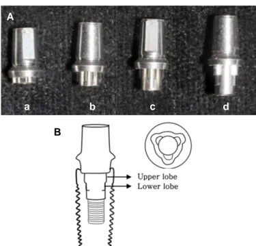
Fig. 1. Internal connection dental implant system. (A) From the left, abutments with internal lengths of 1, 2, 3, and 4 mm (a, b, c, and d, respectively); the abutment com- prised double lobes, including an upper lobe and a lower lobe, (B) Longitudinal and cross sectional views of the implant fixture complex.
A
B
a b c d
Measurement of the initial removal torque
To measure the initial removal torque, the screw was rotated clock- wise to 30 Ncm, according to the manufacturer's instructions, with a digital torque gauge (Model MGT-12, Mark 10 Corp., New York, NY, USA). After 10 minutes, it was again rotated clockwise.
After five min, the initial removal torque was measured with the same torque gauge, and this measurement was recorded. The screw was tightened and loosened three times, respectively, for each specimen. The average of the three removal torques was used as the initial removal torque.
Repeated loads
A fatigue testing machine (dental chewing simulator, R&B, Inc., Daejeon, Korea) powered by compressed air applied an appropriate load onto the embedded specimen, with a dead weight as the load. A globe with a diameter of 4 mm was attached to the bot- tom of the weight, which contacted the specimen. Then, a load was applied to an area 4 mm away from the center of the crown in order to reproduce an eccentric occlusion force. To increase the bending movement, the load was applied counterclockwise. The load force was set at 0 - 100 N, similar to that of the average chewing force for humans; the number of chewing functions was set at 1.0 × 10⁶(aver- age number of chewing functions per year); and the cycle was set at 2 Hz.20-23After every 50,000 chewing functions, the machine was stopped, and the loosening and flexure status of the specimen were observed.
Measurement of the removal torque after the load application After 1.0 × 10⁶repeats of the chewing function, the implant fix- ture and upper structures were firmly fixed, and the removal torque was measured with the same torque gauge. Then, this mea-
surement was compared with the initial removal torque, and the dif- ference was recorded.
Statistical analysis
The Kruskal-Wallis test, a non-parametric method, was per- formed with SPSS software (ver. 17.0, SPSS, Inc., Chicago, IL, USA) to compare the changes in the removal torque before and after the load among the four groups. The association between the internal connection length and the change in the removal torque was also ana- lyzed.
Scanning electron microscopy (SEM) analysis
SEM (Model S-3000, Hitachi, Tokyo, Japan) was used to exam- ine the surface of the abutment screw and the internal connection of the abutment. The changes in the abutment screw and the surface of the internal abutment connection after the load was applied were evaluated.
Results
Change in the removal torque
The average removal torques measured before and after the load are shown in Table 1. The Kruskal-Wallis test was used to eval- uate the association between the length of the internal abutment con- nection and the change in the removal torque. The change in the aver- age removal torque varied between the groups, but not significantly (P > .05) (Table 1 and Fig. 4). No specimen showed complete screw loosening or flexure, and the removal torque after the load was greater than 20 Ncm in all specimens. The initial removal torque was about 80 - 90% of the applied torque, and slightly differed with dif- ferent screws.
Fig. 2. Implant crown fabrication. Crowns were cast with Ni- Cr; all crowns were of one size. A hole was made in the crown to measure the removal torque value of each specimen.
A B
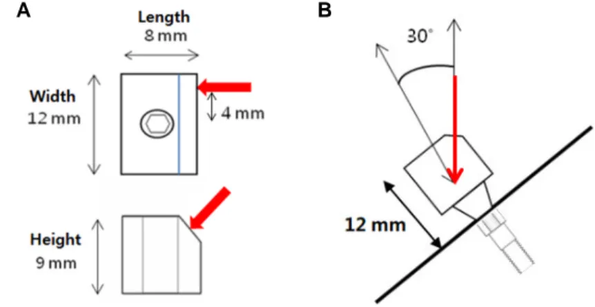
Fig. 3. Crown refinement and fixation. (A) Schematic diagram of implant crown and loading direc- tion (red arrows). (B) Schematic diagram of implant assembly embedded in clear resin. It was fixed at a 30�angle to the long axis of the implant.
SEM analysis
The surfaces of the abutment screws in all four groups showed slight damage due to the load application. However, no abutment screws showed bending, severe abrasion, or fracture (Fig. 5). The internal abutment connection in group B, C and D was damaged only in the
lower lobe (Fig. 6).
The images show the Ti alloy abutment screw inside an internal abutment. The group A,B,C and D represent different lengths of inter- nal abutment connections (see Fig. 1A).
Table 1. Initial reverse torque value (RTV), post loading RTV, and the difference between the initial and post loading RTVs
Specimen no. Initial RTV Mean (SD) initial RTV Post loading RTV Mean (SD) post RTV differences
(Ncm) (Ncm) (Ncm) loading RTV (Ncm)
Group A (1 mm)
1 24.0 20.5 -3.5
2 26.4 20.6 -5.8
3 25.5 25.7 (1.0) 24.5 22.4 (1.8) -1.0
4 26.0 23.7 -2.3
5 26.4 22.9 -3.5
Group B (2 mm)
1 24.4 20.8 -3.6
2 24.2 22.3 -1.9
3 24.4 25.3 (1.4) 22.1 22.7 (2.1) -2.3
4 25.7 22.3 -3.4
5 27.6 26.3 -1.3
Group C (3 mm)
1 26.0 24.7 -1.3
2 24.0 21.7 -2.7
3 25.4 25.3 (0.9) 23.7 23.6 (1.2) -1.7
4 26.3 23.1 -3.2
5 24.8 24.6 -0.2
Group D (4 mm)
1 24.5 24.3 -0.2
2 24.6 22.3 -2.3
3 24.5 24.8 (1.2) 24.7 23.5 (1.6) -0.8
4 23.5 21.2 -2.3
5 26.8 24.9 -1.9
Fig. 4. Means and standard deviations of the differences between initial and final RTVs. The groups represent different lengths of internal abutment connec- tions (see Fig. 1A).
0 -1 -2 -3 -4 -5 -6 NCm
Group
A B C D
Fig. 5. SEM images of abutment screw surfaces (×200 original magnification).
(A) Ti alloy abutment screw into 1 mm internal abutment, (B) Ti alloy abutment screw into 2 mm internal abutment, (C) Ti alloy abutment screw into 3 mm inter- nal abutment, (D) Ti alloy abutment screw into 4 mm internal abutment.
A B
C D
Discussion
A joint-separating force that is greater than the clamping force can cause screw loosening due to loss of the preload. External forces which can cause loss of the preload include contacts made during lateral, anterior, and non-functional movements or poor-fitting prostheses.6,16 Therefore, the purpose of screw tightening is to create sufficient clamp- ing force, and it must provide a maximum preload under the fatigue limit. In this study, a torque of 30 Ncm was applied, according to the manufacturer's recommendation; then, 10 minutes later, the abutment screw was tightened again with the initial torque. This was suggested by Siamos et al.,9to provide a maximum preload, because they found that the initial torque lost 2 - 10% of the preload due to the settling effect. It was assumed that the initial torque removal (after the tightening) would differ among the screws.
From the result of the present study, it was found that the initial torque removal value was 80 - 90% of the initial torque. This decrease was most likely due to the loss of the preload due to the set- tling effect. This might be explained by differences in the implant system, the material used in the screw, or the manufacturing process, which might confer different features to individual screws of the same implant system.20,22
The implant used in this study had an internal abutment length of 4 mm with a three-lobe form. This allowed correct abutment join- ing, and the long internal connection increased the stability of the
screw joining.24Steinebrunner et al.19reported that the tube connection implant with a long internal length was more advantageous than the external or internal connection implant in terms of its flexure strength and durability. They noted that, from a mechanical engi- neering point of view, when the ratio of the internal diameter of the tube to the internal length of the joint was greater than 1.4, the implant fixture would be stable. The long internal connection implant sat- isfies this requirement, and prevents screw loosening by mini- mizing micromovements. In this study, this assumption was tested by investigating whether the internal length affected the degree of screw loosening or the change in the removal torque after the load application. However, no significant differences among different internal abutment lengths were identified. However, average removal torque decreased with decreases in the internal length and this may be related to the ratio of the tube diameter to the inter- nal length of the joint. When the ratio was 1.4 or more and the inter- nal length of the abutment was 4 mm, stability was observed under repetitive loads. Although the abutments with a ratio below 1.4 showed an average decrease in the removal torque, the average decrease was 3 Ncm or less after load application; this indicated that the screw joint was stable under the conditions tested in this study.
No specimen showed complete screw loosening or flexure. Nearly all specimens maintained 80% or more of their initial removal torque and stability at the joint between the implant abutment and the fix- ture.
Based on these results, it is reasonable to assume that mechani- cal resistance due to the rotation resistance form of the upper sec- tion and the shape of the implant abutment screw may have more influence than internal length on the stability of the implant abut- ment and fixture. Wiskott et al.13investigated the fatigue strength in the Replace select system, and reported that the rotation resis- tance form not provide mechanical resistance. In this study, the SEM analysis revealed that there was no resistance to rotational torque in the upper lobes, but considerable abrasion occurred in the lower lobes.
This indicated that there was mechanical resistance in the lower lobe.
Piermatti et al.25studied the shape of the implant abutment screw and the stability of the connection; they reported that the torque decreased when a thicker, special form of screw was used. In this study, we used screws with a thread of 2.0 mm and a long upper part with a thickness of 2.5 mm; this could have stabilized the connection between the implant abutment and the fixture, and thus, prevented differences in the removal torques.
We also found that the average difference in the removal torque decreased with decreases in the length of the internal connection, but not significantly. In addition, any complete screw loosening or flexure was not found. This suggested that the residual torque could maintain the implant system for a long time in clinical prac- Fig. 6. SEM images of internal abutment connection surfaces (×150 original mag-
nification). (A) The lobe surface of a 1 mm internal abutment, no damage was observed;
(B) upper lobe and lower lobe surfaces of a 2 mm internal abutment, upper lobe showed some damage, and the lower lobe showed significant damage and scratch- es; (C) lower lobe surface of a 3 mm internal abutment was more scratched than the upper lobe; (D) lower lobe surface of a 4 mm internal abutment showed sig- nificant scratch marks compared to other surfaces.
A B
C D
tice. Consequently, we concluded that the length of an internal con- nection implant would not significantly influence the flexural strength or anti-rotation resistance of a screw joint. Thus, the commercial availability of shorter internal abutments would be use- ful. An abutment with a shorter internal length would facilitate the prosthetic process and the maintenance of implant stability, particularly when the implant has to be removed and adjusted to a more favor- able implant direction. The use of a thick, long screw may also facil- itate maintaining the stability of an implant system. Our results are based on only five specimens per group. Long term studies with more specimens would enable a determination of the threshold value of the torque at which complete screw loosening occurs.
Conclusion
Within the limitation of study, no complete screw loosening or flex- ure was observed in any groups; the stability of the implant system was maintained with all abutment lengths tested and therefore, there was no significant effect of the abutment length on the degree of screw loosening.
ORCID
Young-Bum Park https://orcid.org/0000-0003-4177-1947 Hyunmin Choi https://orcid.org/0000-0002-9479-3587 Jae-Hoon Lee https://orcid.org/0000-0003-2281-8885
References
1. Goodacre CJ, Kan JY, Rungcharassaeng K. Clinical complications of osseointegrated implants. J Prosthet Dent 1999;81:537- 52.
2. Pjetursson BE, Brägger U, Lang NP, Zwahlen M. Comparison of survival and complication rates of tooth-supported fixed den- tal prostheses (FDPs) and implant-supported FDPs and single crowns (SCs). Clin Oral Implants Res 2007;18:97-113.
3. Jemt T, Laney WR, Harris D, Henry PJ, Krogh PH Jr, Polizzi G, Zarb GA, Herrmann I. Osseointegrated implants for single tooth replacement: a 1-year report from a multicenter prospec- tive study. Int J Oral Maxillofac Implants 1991;6:29-36.
4. Becker W, Becker BE. Replacement of maxillary and mandibu- lar molars with single endosseous implant restorations: a ret- rospective study. J Prosthet Dent 1995;74:51-5.
5. McGlumphy EA, Mendel DA, Holloway JA. Implant screw me- chanics. Dent Clin North Am 1998;42:71-89.
6. Winkler S, Ring K, Ring JD, Boberick KG. Implant screw me- chanics and the settling effect: overview. J Oral Implantol 2003;29:242-5.
7. Sakaguchi RL, Borgersen SE. Nonlinear contact analysis of pre- load in dental implant screws. Int J Oral Maxillofac Implants 1995;10:295-302.
8. Haack JE, Sakaguchi RL, Sun T, Coffey JP. Elongation and pre- load stress in dental implant abutment screws. Int J Oral Maxillofac Implants 1995;10:529-36.
9. Siamos G, Winkler S, Boberick KG. Relationship between im- plant preload and screw loosening on implant-supported pros- theses. J Oral Implantol 2002;28:67-73.
10. Cavazos E, Bell FA. Preventing loosening of implant abutment screws. J Prosthet Dent 1996;75:566-9.
11. Aboyoussef H, Weiner S, Ehrenberg D. Effect of an antirota- tion resistance form on screw loosening for single implant-sup- ported crowns. J Prosthet Dent 2000;83:450-5.
12. Binon PP. The spline implant: design, engineering, and eval- uation. Int J Prosthodont 1996;9:419-33.
13. Wiskott HW, Jaquet R, Scherrer SS, Belser UC. Resistance of internal-connection implant connectors under rotational fatigue loading. Int J Oral Maxillofac Implants 2007;22:249-57.
14. Dixon DL, Breeding LC, Sadler JP, McKay ML. Comparison of screw loosening, rotation, and deflection among three implant designs. J Prosthet Dent 1995;74:270-8.
15. Ohrnell LO, Hirsch JM, Ericsson I, Brånemark PI. Single-tooth rehabilitation using osseointegration. A modified surgical and prosthodontic approach. Quintessence Int 1988;19:871-6.
16. Cibirka RM, Nelson SK, Lang BR, Rueggeberg FA. Examination of the implant-abutment interface after fatigue testing. J Prosthet Dent 2001;85:268-75.
17. Bambini F, Lo Muzio L, Procaccini M. Retrospective analysis of the influence of abutment structure design on the success of implant unit. A 3-year controlled follow-up study. Clin Oral Implants Res 2001;12:319-24.
18. McGlumphy EA, Robinson DM, Mendel DA. Implant su- perstructures: a comparison of ultimate failure force. Int J Oral Maxillofac Implants 1992;7:35-9.
19. Steinebrunner L, Wolfart S, Ludwig K, Kern M. Implant- abutment interface design affects fatigue and fracture strength of implants. Clin Oral Implants Res 2008;19:1276-84.
20. Khraisat A, Hashimoto A, Nomura S, Miyakawa O. Effect of lateral cyclic loading on abutment screw loosening of an external hexagon implant system. J Prosthet Dent 2004;91:326-34.
21. Wiskott HW, Nicholls JI, Belser UC. Stress fatigue: basic principles and prosthodontic implications. Int J Prosthodont 1995;8:105-16.
22. Tsuge T, Hagiwara Y. Influence of lateral-oblique cyclic load- ing on abutment screw loosening of internal and external hexagon implants. Dent Mater J 2009;28:373-81.
23. Gibbs CH, Mahan PE, Mauderli A, Lundeen HC, Walsh EK.
Limits of human bite strength. J Prosthet Dent 1986;56:226-9.
24. Lang LA, Wang RF, May KB. The influence of abutment screw tightening on screw joint configuration. J Prosthet Dent 2002;87:74-9.
25. Piermatti J, Yousef H, Luke A, Mahevich R, Weiner S. An in vitro analysis of implant screw torque loss with external hex and internal connection implant systems. Implant Dent 2006;15:427- 35.
ORIGINAL ARTICLE
내측 연결 임플란트에서 지대주 내부길이가 나사 풀림에 미치는 영향
김지선
1a∙박영범
1,2a∙최현민
1∙김성태
3∙김현철
4∙김선재
5∙문홍석
1*∙이재훈
1*
1
연세대학교 치과대학 보철학교실,
2연세대학교 치과대학 구강과학연구소, BK21 플러스 통합구강생명과학사업,
3
서울대학교 치과대학 치주학교실,
4부산대학교 치과대학 보존학교실,
5연세대학교 강남세브란스병원 치과보철과
목적: 본 연구에서는 long internal connection 형태의 임플란트 지대주를 내부 연결 길이에 변화를 주어 임플란트-지대주 결합부의 안정성을 비교 평가 해 보고자 하였다.
재료 및 방법: Long internal connection의 임플란트(Replus system, 4.7 × 11.5 mm)를 각각 지대주의 길이에 따라 4개의 군(1, 2, 3, 4 mm 군)으로 나누었고
총 20개의 시편을 사용하였다. 시편을 레진에 매몰하여 고정시키고 100 N의 힘으로 임플란트 장축에 대해 30도의 각도에서 1.0 × 10⁶번의 반복하중
을 가한 후 하중 전 후의 풀림회전력의 차이를 계산하여 95% 유의수준에서 Kruskal-Wallis 검정 방법을 통해 통계 분석하였다.
결과: 지대주 내부 길이에 따른 풀림 회전력의 통계적 유의성은 나타나지 않았으며 (P > .05) 어떤 시편에서도 완전한 나사 풀림이나 나사 파절은 관 찰되지 않았다.
결론: 내측 연결 임플란트에서 지대주 내부길이에 따른 나사 풀림의 정도는 차이가 나지 않았다. (대한치과보철학회지 2017;55:251-7) 주요단어: 나사풀림; 풀림회전력; 내측연결 임플란트; 지대주 내부길이
*교신저자: 이재훈1, 문홍석2
03722 서울 서대문구 연세로 50 연세대학교 치과대학 치과보철학교실
102 2228 3159: e-mail, jaehoon115@yuhs.ac
202 2228 3155: e-mail, hsm5@yuhs.ac
원고접수일: 2017년 2월 20일 / 원고최종수정일: 2017년 6월 1일 / 원고채택일: 2017년 6월 19일
2017 대한치과보철학회
이 글은 크리에이티브 커먼즈 코리아 저작자표시-비영리 3.0 대한민국 라이선스에 따라 이용하실 수 있습니다.
c cc
a이 두 저자는 본 연구에 동일한 기여를 하였음.