Design a Laboratory Rotating Test Bench for the Multi-Channel Dryer Experiment
Sha Wang 1† , Jixian Dong 1‡ , Changke Tan 2 , Bo Wang 1 , Lijie Qiao 1 and Huan Liu 1 Received August 5, 2019; Received in revised form September 21, 2019; Accepted September 24, 2019
ABSTRACT
The dryer of paper machine has problem in discharging condensate water. When the dryer rotates at a high speed, the condensate water that is not discharged in time will form a water ring, resulting in low drying efficiency and high energy consumption. Thus, based on the multi-channel dryer proposed by others, a series of experiments was carried out on multi-channel dryer under static condition. However, due to the fact that the research condition of condensation and heat transfer of multi-channel dryer is not exactly the same as the actual working condition, the multi-channel dryer has not been intro- duced to the market. To address the above problems, this paper presented a rotating test bench which can better simulate the actual working condition of dryer and expounded the working principle of the test bench, as well as the design and calculation of rotary device of the test bench. Finite element analysis software was used to analyze the stress on the dryer channel. In order to avoid resonance problems, modal numerical analysis was conducted on the test bench, which provided experimental conditions for the further study of multi-channel dryer.
Keywords: Paper machine dryer, multi-channel dryer, rotation test bench, research and design, modal numerical analysis
Printed in Korea http://dx.doi.org/10.7584/JKTAPPI.2019.10.51.5.27
1 College of Mechanical and Electrical Engineering, Shaanxi University of Science & Technology, Xi’an, Shaanxi Province, 710021, People’s Republic of China
2 Dongguan Light Asia Amperex Technology Co., Ltd., Dongguan, Guangdong Province,523201,People’s Republic of China
† Corresponding Author: E-mail: [email protected]
‡ Co-corresponding Author: E-mail: [email protected]
1. Introduction
Paper manufacturing industry is an important
basic raw material industry in China’s national
economy. In the process of papermaking, the energy
consumption by drying accounts for over 50% of
the total energy consumption of paper machine.
Thus, one of the main approaches to reduce the energy consumed by drying is to reduce thermal resistance and improve the drying efficiency of dryer. In conventional dryer, vapor condenses to release heat and form condensate water. When the dryer rotates at a high speed, the condensate water cannot be discharged in time, forming a conden- sate water ring and thereby increasing the thermal resistance of the dryer for heat transfer.
1)In order to reduce the thermal resistance caused by the condensate water layer in traditional dryer and improve the drying efficiency, Choi et al. pro- posed a multi-channel interlayer dryer.
2,3)Its working principle is as follows: vapor enters the inner cylinder of the dryer and driven by steam pressure, reaches the other end of the dryer from the inlet end and then enters the interlayer chan- nel, where condensation and heat transfer are completed. Dong et al.,
5,6)based on the interlayer dryer proposed by Choi et al., developed a new multi-channel dryer which has a similar structure to the interlayer multi-channel dryer and whose inner wall is evenly distributed with several rect- angular channels along the circumferential direc- tion. Its working principle is: after passing through the air inlet, vapor directly enters the rectangular channels and condenses and transfers heat in the channels; the condensate water generated during the heat exchange is pushed by the subsequent vapor and thus discharged from the channels. To better discharge the condensate water, a certain angle can be set between the channel and the shaft, which solves the problem of condensate water ring and reduces the thermal resistance of dryer for transferring heat.
The channels of the multi-channel dryer have the same structure and similar heat transfer be- haviors, so Choi et al. and Shin et al. used a rect- angular channel to measure its average heat transfer coefficient.
2-4)The results showed that the
average heat transfer coefficient of multi-channel interlayer dryer could reach 15,000 W/(m
2·K), which was 7-20 times that of the condensation heart transfer coefficient of a traditional dryer.
Yan et al. and Yang et al.,
7-9)through the experi- mental research, found that the mean heat transfer coefficient of a single rectangular channel was 8,000-24,000 W/(m
2·K).
The experimental data of Choi and Yan et al.
were obtained under the static condition of rectan- gular channel. However, in a practical situation, the dryer works under a rotating state. Besides, the multi-channel condensation heat transfer belongs to the single-wall condensation heat transfer. Though there are many international and domestic researches on the heat transfer of rect- angular channels in rotating state,
10-12)few are about single wall heat transfer.
Therefore, a multi-channel dryer rotating test bench was designed in this paper to further study the variation of steam condensation heat coefficient and flow pressure drop in single-wall rectangular heat transfer channel at different rotational speeds and steam mass velocities, which provided some experimental data for the design of multi-channel dryer.
2. Design Principle
The multi-channel dryer is currently in the
experimental research stage, and its design prin-
ciple is shown in Fig. 1. Previous experiments have
been carried out on the condensation heat transfer
coefficient of rectangular channels in multi-channel
dryer under static conditions. To further improve the
experimental data of condensation and heat transfer
of a single and multiple channels under a rotating
state, this paper built a rotating test bench so as to
provide a basis for the further study of the
multi-channel dryer.
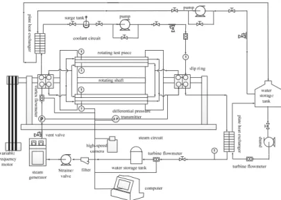
The schematic diagram of the multi-channel dryer rotating test bench is shown in Fig. 2. The test bench mainly includes a rotary device, a steam circulation system, and a coolant circulation system, among which the rotary device is used to drive the test piece to simulate the rotating state of actual dryer, the steam circulation system is used to generate steam and realize the recycling of steam, and the coolant circulation system is used to sim- ulate a wet paper web.
The rectangular channel component is fixed on the rotating disk by T-bolts and rotates with the
disk. The vapor generated by the steam generator enters the channel through a vapor-liquid electric slip ring; after passing through the channel, the vapor is cooled by the plate heat exchanger and then enters the water storage tank again. Cooling water is used as a coolant in this test. The cooling water enters the channel through the vapor-liquid electric slip ring; after the cooling water flows through the channel, it is cooled by a plate heat exchanger, thereby realizing the circulation of cooling water. The power to rotate is provided by the variable frequency motor in the rotary device.
Fig. 1. Design principle of the multi-channel dryer.
Fig. 2. Schematic diagram of multi-channel dryer rotating test bench.
3.2 Channel component
The channel component is the test piece of this study which is used to study the changes of the temperature and flow pattern of steam in the channel. The channel component is mainly com- posed of channel, gasket, PC board, PC board gland, and coolant channel cover plate, as shown in Figs. 4 and 5. Since the steam condensation flow pattern in the channel needs to be captured by high-speed camera, the pressure plate on the side of steam channel is made of transparent PC plate.
8 thermal resistances are distributed on the upper and lower sides of the channel to detect the changes in steam and wall temperatures.
During rotation, the channel bends owing to cen- trifugation, which affects the reliability of the equipment. There are two engineering methods to calculate the deformation of the structure of the channel under the centrifugal force field, i.e., the quadratic element method and the finite element The data of parameters during the test are
obtained through the temperature sensor, the differential pressure transmitter, the pressure transmitter, and the flowmeter.
3. Design and Calculation of Rotary Device
3.1 Components of rotary device
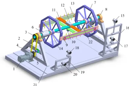
The rotary device is mainly composed of a rotating disk, a rectangular channel component, a trans- mission shaft, a main frame, a fixed snap ring, a vapor-liquid electric slip ring, a thermal resistance gathering module, a side frame, a thermal resis- tance, a flowmeter, a tensioning gear, and a transmission system, as shown in Fig. 3. The rotat- ing radius of the test bench is 800 mm; the length of the rectangular channel is 1,100 mm; and the rotational speed is set to 140-318 r/min.
Fig. 3. Structure drawing of rotary device. 1-Variable frequency motor, 2-Synchronous belt,
3-Big belt wheel, 4-Small belt wheel, 5-Tensioning gear, 6-Vapor-liquid electric slip ring,
7-Disk, 8-Bearing, 9-Channel component, 10-Power module, 11-Support plate,
12-Thermal resistance gathering module, 13-Thermal resistance, 14-Fixed snap ring,
15-Vortex shedding flowmeter, 16-Side frame 1, 17-Pressure transmitter, 18-Differential
pressure transmitter, 19-Side frame 2, 20-Turbine flowmeter, 21-Underframe, 22-Main shaft.
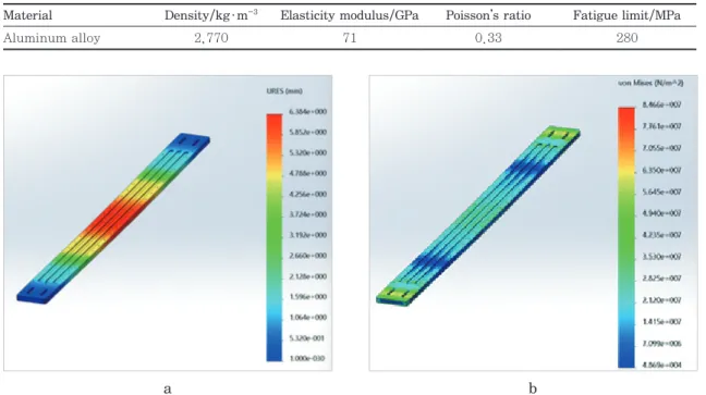
method. The quadratic element method is to sim- plify the channel into a plane stress problem to solve. Thus, the finite element method is adopted in this paper. When the rotational speed is the highest, the centrifugal force is the largest. As both ends of the channel are fixed, the maximum centrifugal force is evenly applied on the channel plane to perform simulation. The channel is made of aluminum alloy, whose material properties are listed in Table 1.
The simulation results are shown in Fig. 6. The results show that the deformation of the middle part of the channel is the largest, reaching 6.384 mm, and the maximum stress of the channel is smaller than the yield stress. The allowable deflec- tion of channel is
y = l l 750 500
~
where l is the total length of the channel, so the maximum allowable deformation of the channel is 2.2 mm. As the stress deformation at the middle of Fig. 4. Structure diagram of channel component.
Fig. 5. Structure diagram of channel component.
1-Retangular channel, 2-Gasket 1, 3-Gasket 2, 4-PC board, 5-Gasket 3, 6-PC board gland, 7-Coolant channel coverplate, 8-Pipe joint, 9-Thermo- couple.
Fig. 6. Stress-strain diagram of channel.
Table 1. Structural material properties of channel
Material Density/kg·m
-3Elasticity modulus/GPa Poisson’s ratio Fatigue limit/MPa
Aluminum alloy 2,770 71 0.33 280
a b
the channel is greater than 2.2 mm, to reduce the deformation, a group of support plates are in- stalled at the middle of the channel to increase its strength. Simulation analysis is conducted on the improved channel; the results are shown in Fig. 7.
The results show that the deformation of the channel decreases significantly and the maximum deformation is 0.4 mm, which is less than the allowable deflection. Therefore, the improved channel is adopted in this paper.
3.3 Frame of the test bench
The frame of the rotating test bench is composed of a main frame and two side frames. The main frame, which is 2,900 mm in length, 1,350 mm in width, and 665 mm in height, is used to support the rotating shaft and fix the motor. The two trapezoidal side support plates of the main frame with large strength and small mass are made of 80×80 mm box iron. The two side frames, which are made of 40×40 mm square tube, are used to fix the vortex flowmeter, the turbine flowmeter, the pressure transmitter, and the differential pressure transmitter.
3.4 Shaft system
The shaft system used in the test mainly consists of a main shaft, a rolling bearing, a vapor-liquid electric slip ring, a disk, and a fixed snap ring, among which the main shaft is driven by a vari- able-frequency and variable-speed motor whose maximum speed is 318 r/min.
The inner diameter of the main shaft is 58 mm, the outer diameter is 80 mm, and the length is 2,463 mm. The vapor-liquid electric slip ring used is a Slip Ring which can withstand a steam tem- perature of 150°C and a pressure of 0.5 MPa.
The disk, whose inner diameter is 80 mm and wall thickness is 30 mm, is welded into an octago- nal shape with 63×63 mm box iron. Eight ribs that are 4 mm in thickness are used to increase the strength of the disk. The disk is fixed on the shaft through connections. To prevent the disk from moving along the shaft, a fixed snap ring is in- stalled on both sides of the disk respectively. The snap ring consists of two half rings which are fixed on the shaft by bolts. There are 9 mm wide and 285 mm long rectangular holes on the sides of the disk’s box iron, which are used to adjust the incli-
Fig. 7. The stress-strain diagram of the improved channel.
a b
nation angle between the channel and the main shaft. The maximum inclination angle is 10°.
3.5 Drive system
In this test, the influences of different rotational speeds on heat transfer coefficient of the rectangular channel need to be studied, so a variable-frequency and variable-speed motor is used to provide power for the main shaft. By adjusting the frequency converter, the different rotational speeds can be realized.
The total mass of the rotating disk, channel com- ponent, and support plate is about 25 kg, 21 kg, and 2.7 kg, respectively.
According to the theoretical mechanical for- mula
13):
J mR =
2[1]
Where m is the mass of support plate (kg) and R is the turning radius (m).
Thus, the rotational inertia of the two support plate is J
1=0.96 kg·m
2, and the rotational inertia of the two channel components is J
2=6.72 kg·m
2.
According to the theoretical mechanical for- mula
13):
J = 1 mR 2
2