Study on the Drive Parameters of a High-precision Basis Weight Control Valve
Bo Wang, Wei Tang
1†, Jixian Dong and Feng Wang
2Received February 21, 2017; Received in revised form June 18, 2017; Accepted June 20, 2017
ABSTRACT
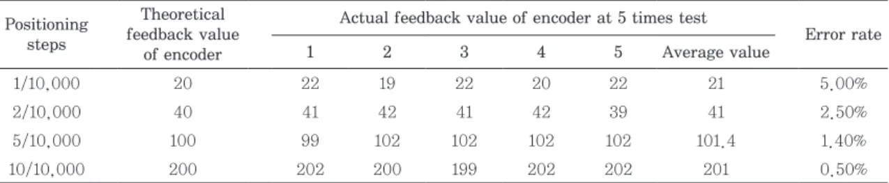
Decreasing precision or mechanical damage may occur in basis weight valves because of excess design torque valves. Stepping motor driver current values are set at the rated motor current or are based on practical experience. Applied technological research on current setting values was conducted in this paper. A current-setting experimental de- vice was developed to solve this problem. The drive parameters include the drive current value, mechanical strength of valve actuator and the state holding current value were tested. Finally, the acceleration time for the trapezoidal velocity curve was calculated, which was helpful to improve the positioning precision of the valve. The test result with a sample diameter of a DN125 basis weight valve showed that the reasonable current value stage was 3.71 A, and the state holding current value stage was 50%. Then, the acceleration and deceleration times of the trapezoidal velocity curve were both set at 0.01 seconds. The positioning precision was able to match the requirements of a basis weight control valve for 10,000 steps in which an error of 1 step was less than 5.0% during 10,000 positioning steps under such drive parameters.
Keywords: Basis weight control valve, stepping motor driver, driving torque, drive current, trapezoidal velocity curve
• College of Bioresources Chemical and Materials Engineering of Shaanxi University of Science & Technology, Xi’an, Shaanxi Province, 710021, People’s Republic of China
1 Industrial Automation Institute of Shaanxi University of Science & Technology, Xi’an, Shaanxi Province, 710021, People’s Republic of China
2 Zhejiang Linuo Flow Control Technology Co., Ltd., Rui’an, Zhejiang, 325200, People’s Republic of China
† Corresponding Author: E-mail: [email protected]
Printed in Korea http://dx.doi.org/10.7584/JKTAPPI.2017.06.49.3.41
1. Introduction
The basis weight includes the machine direction (MD) and cross direction (CD) indicators, and the
weight is an important indicator of paper.
1)The
basis weight of MD is controlled by means of sta-
bilizing the pulp consistency and adjusting the
pulp flow precisely by the basis weight control
valve.
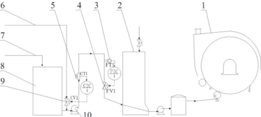
2)The technological process of basis weight is shown in Fig. 1. After pulping, the pulp is sent to a pulp storage tank, and the pulp is diluted with white water through a consistency control loop (CIC1) to make the consistency steady. The valve (CV1) is used to adjust the flow of white wa- ter, and the pulp consistency transmitter (CT1) is used to detect the real-time consistency of the pulp. Next, the pulp flow is controlled by the flow control loop (FIC1) to cause a steady flow, the ba- sis weight valve (FV1) is used to adjust the flow of pulp, and the flow transmitter (FT1) is used to de- tect the real-time flow of pulp to forming a con- trol loop. Further, the pulp is diluted by a white water tank and then sent to the high-speed tissue paper machine to form tissue paper. The basis weight of the tissue paper is fully controlled by the basis weight control valve. Due to the high-speed process (usually greater than 1,000 m/min), the paper is extremely thin, and the basis weight of paper is very low. Therefore, the paper machine is not typically equipped with quality control systems (QCS). This technological process is based on the precision and reliability of the basis weight control valve.
The basis weight control valve developed by the research group of the author comprised an actua-
tor, a V-type ball valve and a controller.
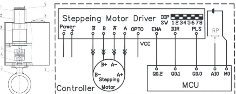
3,4)Fig. 2 illustrates the mechanical structure and control principle. The stepping motor is fitted on a plane- tary reducer, and the reducer is fixed on a support plate. The ball valve and actuator are bound to- gether with screw bolts. The torque is transmitted by a high-rigidity coupling, which connects the valve stem and the output shaft of the reducer. A valve position indicator was installed on top of the actuator shell.
The micro controller unit (MCU) and stepping motor driver were installed in the controller of the basis weight control valve. The stepping motor driver drove the stepping motor. Then, the step- ping motor driver was controlled by three signals, the pulse (PLS), direction (DIR) and enable (ENA), which were sent by the MCU.
5)The controller could control the valve to adjust the pulp flow by means of control the stepping motor of valve. A rotary potentiometer was installed in the valve position indicator and connected with the analog port of the MCU. Then, the valve controller could detect the valve position.
The stepping motor driver had a DIP Switch (Dual in-line package switch), as shown in Fig. 2.
Eight switches, denoted SW1~SW8, in the step- ping motor driver were used in this type of valve.
Fig. 1. Basis weight control technological process of high speed tissue paper machine
(1. High-speed tissue paper machine, 2. White water bucket, 3. Flow-meter, 4. High-precision basis
weight control valve, 5. Consistency transmitter, 6. White water, 7. Pulp, 8. Pulp storage, 9. Consis-
tency control valve, 10. Pulp pump).
The SW1~SW3 DIP Switches were used to set the drive current value of the stepping motor, which has 8 stage levels that can be set using the cur- rent range of 2.0 A to 6.0 A, which determine the drive torque value of the stepping motor. The DIP Switch of SW4 was used to set the state holding current and could be set at a level of 50% or 100%, which determines the state holding torque value of the stepping motor. The DIP Switches of SW5~
SW8 were used to set the subdivision rate of the stepping motor, which has 16 stage levels that can be set at subdivision rates of 400 pulse/r to 51,200 pulse/r and determines the number of pulses re- quired to make the stepping motor rotate one rev- olution.
6)The existing basis weight control valves were Neles ACE from Metso Flow Control Inc and VBW- 1100 from BTG Instruments AB.
7-9)The drive methods were different for each of the valves. A stepping motor drove the ACE valve, and a syn- chronous motor drove the VBW valve. This paper mainly discusses the valve driven by a stepping motor. Although the motor current limit for dif- ferent valve sizes was mentioned in the ACE valve, the reasonable current value was not given, and the method of how to set the suitable current val- ue was also not provided. Many researchers have
only demonstrated that the drive torque has a qualitative proportional relationship with the drive current of the stepping motor driver. However, the corresponding relationship between the drive torque values and drive current value remains un- known.
10)Thus, it is difficult to determine the current setting value of the stepping motor driver and the reasonable setting values of SW1~SW4.
Therefore, the engineering application of these apparatuses is questionable if the current value is set optionally or set at the rated current value of stepping motor. This model does not guarantee that the torque of stepping motor matches the rated design torque of the basis weight control valve. If the current value is set at a low level, the stepping motor cannot overcome the value of re- sistance during running processes because its torque reserve is not enough. In contrast, the driven torque value is greater than the rated de- sign torque of the valve, so much so that it en- dangers its safety because the current value level was set higher than the actual demand value. The aim of this study is to solve this problem and find a way to set the reasonable current value that matches the rated design drive torque and the holding torque for the stepping motor of the basis weight control valve.
Fig. 2. Mechanical structure and controller of basis weight control valve developed by authors’ re- search group
(1. Motor cover, 2. Stepping motor, 3. Planetary gear reducer, 4. Coupling, 5. Valve shaft, 6. V type
ball valve, 7. Controller, 8. Valve position indicator, 9. Hand wheel).
2. Materials and Methods
2.1 Materials
2.1.1 Development of experimental system for stepping motor drive current level pa- rameters
A reasonable current value can ensure the drive torque matches the rated design torque of the valve.
11,12)Additionally, the hold torque and accel- erative torque of the stepping motor and the me- chanical strength of the valve should be checked to identify whether they are acceptable. However, the relationship between the drive torque and dif- ferent current setting values was previously un- known because only the rated torque of the step- ping motor is provided by motor manufactur-
ers.
13-15)Thus, the maximum current value allows
the motor to run safely for a long time. The step- ping motor will provide its maximum torque at the rated current. A current-setting experimental ap- paratus was developed for the valve stepping mo-
tor driver that can be used to determine the opti- mum current setting value of the valve, as shown in Fig. 3. A magnetic powder brake ensured the equal torque of the stepping motor.
16,17)The rea- sonable current value setting level was examined by testing the positioning precision of the stepping motor at different drive current values.
2.1.2 Working principle of the experimental de- vice
As shown in Fig. 3, the stepping motor with the same type of valve and an optical encoder were in- stalled on the back shaft of the motor, and a mag- netic powder brake was mounted on the platform of the device as well. The two are connected together through a coupling. A magnetic powder brake pro- vided the load torque of the stepping motor. A ten- sion controller controlled the load torque size by adjusting the exciting current of the magnetic powder brake. The relationship of the torque value and the exciting current of the brake were mea- sured by a torque wrench. The hold torque value was measured by the torque wrench as well. The optical encoder was used to measure the accurate rotation angle. The phenomenon of whether the losing step was accrued can be judged by comparing the rotation angle of the stepping motor with the number of control pulses that were sent to stepping motor driver. Then, the positioning precision of the stepping motor at different current value levels was determined. Finally, the reasonable current value level of stepping motor drive that matches with the rated design torque could be obtained.
2.1.3 Design of the control system for the ex- perimental device
The main capabilities of the control system in- clude measuring the rotation angle of the motor, controlling the movements of the stepping motor, and adjusting the exciting current of the magnetic powder brake. The electrical control system sche- Fig. 3. The experimental device of stepper mo-
tor for reasonable current setting value (1. Torque wrench, 2. Optical encoder, 3.
Stepper motor, 4. Controller, 5. Platform, 6. Coupling, 7. Magnetic powder brake, 8.
Tension controller, 9. Stepper drive, 10. DC
power).
matic of the experimental device is shown in Fig.
4. The PLC (Programmable Logic Controller) con- troller was the key part of the control system.
High-speed pulses at the output terminal (Q0.0) generated the control pulse signal, and it was connected with the pulse signal input terminal (PLS) of the stepping motor drive. The directional signal was controlled by terminal (Q0.1) of the PLC, and it was connected with the direction sig- nal input terminal (DIR). The torque of the step- ping motor was controlled by the enable control terminal (ENA) of the motor drive, and it was connected with the terminal (Q0.2) of the PLC.
The drive current of the stepping motor was con- trolled by the DIP Switches of the stepping motor drive. Connecting the current output terminals with the A, B phase winding of the stepping motor transmitted the drive current. The two-phase pulse signal of the optical encoder was sent to the high speed input signal channels of I0.3 and I0.4 in the PLC input terminals. The mode of the A/B phase quadrature counter was configured in the PLC control program. Therefore, the count value reached 4,000 for each turn of the stepping motor.
The accuracy of the optical encoder was increased
to 4 times that of the single phase counter mode, which only has a 1,000 count value.
18)The brake torque value was controlled by the analog voltage signal that was generated by the PLC controller.
The analog output channel with terminals M and V of the PLC connected the exciting current con- trol channel with terminals A- and A+ of the tension controller for the magnetic powder brake.
Several DC power settings were used to satisfy the different rated voltage requirements of the PLC, the stepping motor drive, and the optical encoder.
2.2 Methods
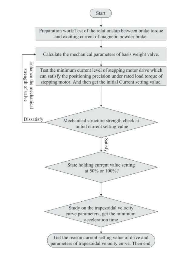
The testing procedure is shown in Fig. 5. First, the relationship of the brake torque and the excit- ing current needed to be measured. Second, the mechanical parameters needed to be analyzed.
Then, the equivalent load torque that matched the design load torque was applied to the stepping motor. The initial drive current value was obtained by searching the minimum current value, which can drive the motor positioning accurately without any step loss. The drive current value was char- acterized by the average current value and the peak current value. The average torque was relat- ed to the average current value of the stepping drive, so it influenced the positioning precision during the whole process. Similarly, the peak torque was related to the peak current value of the stepping drive, so it influenced the maximum drive torque of the stepping motor. The mechani- cal strength needed to be checked because the maximum torque that the stepping motor could supply at the peak current value could exceed the permissible mechanical strength range when the valve was stuck or a mechanical fault occurred and the motor moved on continuously. The static holding torque of stepping motor was then checked to determine whether it should be set at a level of 50% or 100%. To improve the positioning precision, the trapezoidal velocity curve was used to ensure Fig. 4. Electrical control system schematic of
experimental device.
Calculate the mechanical parameters of basis weight valve.
Get the reason current setting value of drive and parameters of trapezoidal velocity curve. Then end.
Test the minimum current level of stepping motor drive which can satisfy the positioning precision under rated load torque of stepping motor. And then get the initial Current setting value.
Mechanical structure strength check at initial current setting value
Start
Preparation work:Test of the relationship between brake torque and exciting current of magnetic powder brake.
En ha nc e the m ec ha nic al str en gth of va lve
State holding current value setting at 50% or 100%?
Dissatisfy
Sa tis fy
Study on the trapezoidal velocity curve parameters, get the minimum
acceleration time
Fig. 5. Test procedure of drive parameters.
movement occurs smoothly. Then, the trapezoidal velocity curve parameters of the valve-stepping motor, such as the maximum acceleration value and the minimum acceleration time length, were checked. Finally, the reasonable drive parameters were obtained by experiments and analysis.
3. Results and Discussion
3.1 Relationship between brake torque and exciting current of the magnetic pow- der brake
The magnetic powder brake was used to apply the load torque of the stepping motor that equals the resistance torque of the valve equivalent to the motor shaft. Although the brake torque has a proportional correlation with the exciting current, the brake torque was not exactly proportional to the value of the exciting current. The error of the result obtained from curve interpolation was re- ported to always be very large, according to the torque-current curve provided by the manufac- turers.
19)The quantity of the magnetic powders varies and has great impact on the torque-current curve. To achieve an accurate relationship between the brake torque and the exciting current of the magnetic powder brake, an experimental test was conducted to solve this problem. The following experimental procedures were conducted. First, the exciting current was increased by an incre- ment of 0.05 A (or 0.01 A) each time. Second, gradually increasing load torque was applied by a torque wrench. Then, the brake torque provided by the magnetic powder brake under the current
value conditions was obtained. The relationship between the brake torque and exciting current are shown in Table 1.
3.2 Study on the mechanical parameters of the basis weight valve
The mechanical parameters of the basis weight valve need to be confirmed. The mechanical pa- rameters of the basis weight valve with a DN 125 diameter were examined. The rated design torque of valve was 250 N·m.
20)The reduction ratio of the reducing mechanism was 200:1. The execution time was 200 seconds for the valves from the full off states to the full open states. The positioning precision was 10,000 steps. The rotation angle of a single step was 1.8° (θ
0), and the time length of single step was 0.02 S (T
0). The rated load torque of the stepping motor was 1.25 N·m, which was equivalent to the rated design torque of the valve.
The stepping motor was required to provide 1.5 N·m of torque, according to a 20% allowance. The trapezoidal acceleration velocity curve was used to improve the positioning precision of the valve for a smooth speed transition.
21)The design time length was equal both at the acceleration and de- celeration stages for the symmetric relationships of the two stages.
The entire inertia of the basis weight valve was the sum of all parts in transmission, as shown in Eq. [1].
I I I I
2I
m g c v
= + + +
n Eq. [1]
in which I, I
m, I
g, I
c, I
v, and n denote the inertia of the whole valve, inertia of the stepping motor, in-
Table 1. Relationship between brake torque and exciting current Exciting
current (A) 0.05 0.10 0.15 0.20 0.25 0.30 0.31 0.32 0.33 0.34 0.35 0.36 0.37 0.38 0.39 0.40 0.41 0.42 0.43 0.44 0.45 0.46 Brake
torque (N·m) 0.2 0.4 0.6 0.8 1.4 1.5 1.6 1.7 1.8 2.0 2.2 2.3 2.4 2.5 2.6 2.7 2.8 3.0 3.1 3.2 3.3
ertia of the planetary gear reducer, inertia of the coupling, inertia of the ball valve and reduction ratio of the planetary gear reducer, respectively.
The mechanical parameters I
m=2.7 kg·cm
2, I
g=1.15 kg·cm
2, I
c=15 kg·cm
2, I
v=28 kg·cm
2, and n=200 were placed into Eq. [1]. The entire inertia of the basis weight valve was equal to 3.85 kg·cm
2.
3.3 Test of the drive current level of the stepping motor drive
The aim of this test was to measure the mini- mum current level of the stepping motor drive that could satisfy the positioning precision under the rated load torque of the valve that was equivalent to the stepping motor.
22)The phenomenon of “los- ing step” occurs when the motor cannot overcome the load torque to be precisely positioned because of the drive current is lower than required.
The stepping motor and driver were used in this paper. The voltage of the stepping drive was 24 VDC. Six current levels and their peak values could satisfy the rated current value of the stepping mo- tor (5.5 A), as follows: 2.00 A (2.4 A), 2.57 A (3.08 A), 3.14 A (3.77 A), 3.71 A (4.45 A), 4.28 A (5.14 A), and 5.43 A (6.52 A). (The in parentheses mean the peak value.) The current value can be set by the DIP Switch of the stepping drive. The posi- tioning precision of the stepping motor was mea- sured by comparing the control pulse generated by the stepping drive. Then, the current values were examined to determine which values could satisfy the requirements of positioning precision.
The positive rotation and reverse rotation mo- tions are normal movements of the stepping motor during the running valve process. To make sure the working conditions of the experimental device were in accordance with the actual basis weight valve, repeated positioning was used to simulate the actual valve status. During positioning testing, the apparatus rotated 50 turns in the forward di- rection and then in reverse direction; each time
the rotation angle was 360°. A high-precision op- tical encoder measured the accuracy of the rota- tion angle. Then, the test results were used to evaluate the positioning precision of the stepping motor. The precision was considered to be high if the final rotational angle is 0 or close to 0, indi- cating that the motion of motor can return to its original position. Otherwise, poor precision was indicated if the rotation angle was largely different from the value of 0. Moreover, the precision could be judged by observing the coupling markers in terms of whether the coupling rotated a full turn.
The precision was considered low if the motor could not rotate a full turn because the drive torque was lower than the resistance torque and the motor was unable to move precisely. Each current value level was repeated three times. The rotation angle values of the stepping motor at rated load torque are shown in Table 2.
Based on the analysis of the experimental data, drive current values at 3.71 A (Ia
0, Average cur- rent value) and 4.45 A (Ip
0, Peak current value) were able to drive the stepping motor to rotate in a complete circle. The final positioning precision error was less than 0.5% during 50 forward and reverse rotations. This current value level was able to satisfy the needs of the drive.
If the current value was set at a level lower than
3.71 A without any testing, the stepping motor
could not drive the valve precisely because its
drive torque was not large enough to overcome the
resistance torque. This problem is difficult to di-
agnose, however. At first, the stepping motor
drove the valve rotation precisely because the re-
sistance was as small as the new mechanical
structure. However, after some period of time, the
precision decreased because of losing steps, and
the stepping motor could not provide enough
torque as the running resistance torque increased
because of mechanical abrasion and valve spool
pollution. The valve could not provide the same
precision as in the initial state, causing a loss of precision after several years of use.
According to the test, the following conclusions could be obtained:
(1) The stepping motor could overcome resistance torque equivalent to the rated design torque of the valve when the drive current value was set to 3.71 A. The DIP Switch of SW1~3 should be set at a state of 001.
(2) The stepping motor could not overcome the resistance torque equivalent to the rated de- sign torque of the valve if the drive current value was set at a level lower than 3.71 A. The positioning precision of the stepping motor greatly decreased.
(3) On the contrary, there will be more calorific of the stepping motor and stepping motor driver occurred if the drive current value was set higher than 3.71 A.
23)It brought adverse ef- fects on the safety and steady operation of the basis weight control valve.
3.4 Mechanical structure strength check
The current parameters were examined for the stepping drive included the average value and peak value. The average current value determines
the average drive torque value, and the peak cur- rent value determines the maximum drive torque value. The drive torque at the moment of the peak current value was larger than the average current value. The stepping motor continues moving be- cause the upper controller sent the control pulse.
Motion was prevented by mechanical failure or by flowing mediums such as by pulp fibers. There- fore, the torque was still output by the stepping motor, even up to the maximum drive torque val- ue. Mechanical damage occurs if the drive torque exceeds the allowable strength of the mechanical structure.
24)It was necessary, therefore, to mea- sure the maximum drive torque value of the step- ping motor at the initial current setting value and check the mechanical strength of the valve.
The test method for obtaining the maximum drive torque value of the stepping motor at the initial current setting value is described below.
First, the drive current of the stepping motor was set at 3.71 A (the average value) by adjusting the DIP Switch of the driver. Second, forward and re- verse control pulses were sent to the stepping motor driver. Meanwhile, the brake torque gradu- ally increased by increasing the exciting current value of the magnetic powder brake. The maxi- Table 2. Rotation angle of stepping motor at different current value level
Average drive current
vlaue (A)
Rotation angle of forward and reverse
(resolution of encoder is 4,000 P/R) Experimental phenomena
Maximum rotation angle (°)
Conclusion
1 2 3 Average
2.00 390 212 278 Meaningless Cannot rotate
complete circle
13.52 Drive current is less than need
2.57 1,242 364 1,563 Meaningless Ditto 47.68 Ditto
3.14 2,566 1,342 2,836 Meaningless Excessive vibration.
Occasionally rotates complete circle
360 Ditto
3.71 2 3 1 2.00 Able to rotate
complete circle
360 Drive current can satisfy the
need
4.28 6 -1 2 2.33 Ditto 360 Ditto
5.43 1 3 3 2.33 Ditto 360 Ditto
6.00 5 0 1 2.00 Ditto 360 Ditto
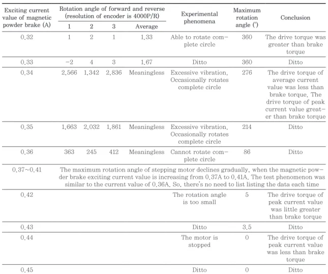
mum drive torque value of the stepping motor was equal to the brake torque of the magnetic powder brake until the motor could not drive the magnetic powder brake. The experimental test results are shown in Table 3.
Based on the analysis of experimental data, the positioning precision of the stepping motor had very high accuracy at the corresponding load torque of 1.7 N·m. This drive torque value demon- strated 0.2 N·m reserve of torque compared to the rated torque value of 1.5 N·m. As the exciting cur- rent of magnetic powder brake increased, the brake torque increased also. The motor cannot ro-
tate in a complete circle, so the drive torque at the average current was lower than the load torque and the exciting current value was higher than 0.34 A. The output torque at the peak current val- ue was higher than the load torque because the motor was able to move. The brake torque in- creased with the increasing exciting current. The motor rotated with a smaller angle, and the output torque provided by the stepping motor could pro- vide a peak current closer to the brake torque. The motor was unable to move with any small angle for an output torque equal to the brake torque when the exciting current value of the magnetic powder
Table 3. Maximum drive torque value of stepping motor at the drive current setting value Exciting current
value of magnetic powder brake (A)
Rotation angle of forward and reverse
(resolution of encoder is 4000P/R) Experimental phenomena
Maximum rotation angle (°)
Conclusion
1 2 3 Average
0.32 1 2 1 1.33 Able to rotate com-
plete circle
360 The drive torque was greater than brake
torque
0.33 -2 4 3 1.67 Ditto 360 Ditto
0.34 2,566 1,342 2,836 Meaningless Excessive vibration.
Occasionally rotates complete circle
276 The drive torque of average current value was less than
brake torque. The drive torque of peak current value great- er than brake torque 0.35 1,663 2,032 1,861 Meaningless Excessive vibration.
Occasionally rotates complete circle
214 Ditto
0.36 363 245 412 Meaningless Cannot rotate com- plete circle
86 Ditto
0.37~0.41 The maximum rotation angle of stepping motor declines gradually, when the magnetic pow- der brake exciting current value is increasing from 0.37A to 0.41A. The test phenomenon was
similar to the current value of 0.36A. So, there’s no need to list listing the data each time
0.42 The rotation angle
is too small
5 The drive torque of peak current value was little greater than brake torque
0.43 Ditto 3.5 Ditto
0.44 The motor is
stopped
0 The drive torque of peak current value was less than brake
torque
0.45 Ditto 0 Ditto
brake was adjusted to 0.44 A. The brake torque value was 3.1 N·m at this moment, which equals the maximum torque that the stepping motor can provide at this stepping drive current value.
The valve parts, including the planetary gear re- ducer, the coupling and the valve stem, act as a supporting torque load. Therefore, their allowable strength should be checked. The drive torque in- creased to 620 N·m when the reduction ratio of the planetary gear reducer was 200:1. The rated torque of the planetary gear reducer was 320 N·m, and the maximum allowable torque was 640 N·m. There- fore, the planetary gear reducer satisfies the al- lowable strength requirements. The rated torque of the coupling was 400 N·m, and the instantaneous maximum allowable torque was 1,120 N·m. There- fore, the coupling can also satisfy the allowable stress. The maximum allowable torque of the valve stem was 700 N·m, which was confirmed by the valve manufacturer. Thus, all the valve parts were able to satisfy the drive torque needs. In this case, all parts were suitable for the allowable torque.
If the drive current was set at the rated current of the stepping motor with the rated current value of stepping motor of 5.43 A (6.52 A) without any experimental testing as shown in the article, the actual maximum drive torque was 3.85 N·m ac- cording to a new round of tests. The output torque increased to 770 N·m through the planetary gear reducer with a reduction ratio of 200:1. This torque already exceeds the mechanical strength value of the planetary gear reducer and the V type ball valve. Thus, setting the drive current value at the rated current value of the stepping motor will cause mechanical damage.
According to the test, the following conclusions could be obtained:
(1) The maximal drive torque of the stepping mo- tor was much larger than the drive torque when the stepping motor was steadily running.
Thus, the current was larger than its average
current value.
(2) The mechanical structure of the valve could satisfy the strength requirement when the drive current value was set at 3.71 A.
(3) Mechanical damage may occur if the value was set at a level of 5.43 A, which is equal to the rated current value of stepping motor. This was the largest problem when setting the drive current value by experience rather than by ex- periment; this may cause large valve damage.
3.5 Testing the state holding current setting value
The valve was expected to remain still at fixed opening if the process was steady. The stepping motor remains still when the upper control system does not send a pulse signal to the stepping motor drive. An impact force was experienced when fluid flowed around the valve, and the impact force will be transmitted to the stepping motor because the planetary reducer did not have a self-locking function. The expected value of the holding torque was equal to 1.5 N·m, which was equal to the rat- ed design torque of the valve equivalent of the stepping motor. The stepping motor holding torque depended on the state holding current of the step- ping motor drive. The stem of valve moves and cannot hold its present opening position if the holding torque is lower than the impact torque.
Thus, the valve may become out of control.
The DIP Switch of SW4 was used to set the state holding current value; there were two levels to choose from, 50% or 100%. It is difficult for users to choose, as the manual for the stepping motor only provided the holding torque at the rated cur- rent value. The holding torque value remained unknown, as the current value of the stepping motor was set lower than its rated current value.
To solve this problem, the holding torque must be
measured to determine whether the level of 50% or
100% was suitable for the valve holding torque.
The testing process was as follows:
(1) Dismantle the coupling between the magnetic powder brake and the stepping motor.
(2) Fix the measuring head of torque wrench to the stepping motor shaft.
(3) Set the drive current value to 3.71 A by turn- ing the DIP Switch of SW1~SW3. Similarly, set the state holding current at level of 50% by turning the DIP Switch of SW4.
(4) Without sending any pulse signal to the step- ping motor driver, the stepping motor will re- main stationary by the holding current. Then, the holding torque of the stepping motor can be measured by the torque wrench, which gradually increases the load torque to the mo- tor shaft. The maximal holding torque was obtained when the motor sliding.
According to the experimental results, the maxi- mal holding torque was 2.8 N·m when the state holding current value was set at the level of 50%.
The holding torque was larger than the rated de- sign torque of 1.5 N·m, which was even larger than the drive torque that the stepping motor could provide at 1.7 N·m, as section 3.4 showed.
Therefore, enough holding torque was provided to overcome the fluid impulsive force. This shows that the holding torque is usually larger than the drive torque. As the holding torque could satisfy the needs of valve, there was no need to test the level of 100% state holding current. The holding torque must be larger than the torque when the state holding current was set at value of 50%. In contrast, the calorific value of the stepping motor and stepping motor driver would be higher if the state holding current value was set at 100%, re- sulting in an adverse effect on safety and the steady operation of the basis weight control valve.
According to the test, the following conclusions could be obtained:
(1) The holding torque of the stepping motor could satisfy the needs of the valve. The state of
SW4 should be set at the value of 0 according to the manual of the stepping motor driver.
(2) In contrast, the calorific value of the stepping motor and stepping motor driver will be higher if the state holding current value was set at the level of 100%, resulting in an bring adverse effect on safety and steady operation of the basis weight control valve.
3.6 Study on the trapezoidal velocity curve parameters of the valve-stepping motor
The common method of the stepping motor is controlled by a constant frequency pulse, which can easily cause a lost step. Consequently, the drive torque cannot satisfy the acceleration from the dramatic change of velocity, which accelerates to the rated velocity in a brief moment. Different from previous methods, a trapezoidal velocity curve was adopted to make the motion more smoothly. In ad- dition, consequently, the valve-positioning preci- sion improves.
25)However, the parameters of the trapezoidal velocity curve have a big impact on the positioning precision of stepping motor in the valve.
A lost step will also occur if the acceleration tran- sient time is too short or the acceleration value was too high. The scientific evidence was lacking if the acceleration value was set only by experience. Be- cause the drive torque was unknown, the maximum acceleration value for the stepping motor could not be determined. The experimental value is needed to test the correct acceleration value. The relevant calculations and process are described as follows.
The acceleration of the stepping motor depends on the drive torque, resistance torque and the whole inertia of basis weight valve, as shown in Eq. [2].
M
d- M
f= I a )
1Eq. [2]
in which M
d, M
fand a
1denote the rated drive
torque of stepping motor, the resistance torque
transmitted from the planetary gear reducer which is equal to the design torque of valve, and the maximum acceleration of stepping motor provided, respectively.
When the values M
d=1.5 N·m, M
f=1.25 N·m, and I=3.85 kg·cm
2were substituted into Eq. [2], the maximum acceleration of the stepping motor could be calculated as a
1=649.35 rad/s
2. The acceleration of the practical application was lower than the maximum acceleration that the stepping motor could provide because the motor had enough torque to achieve the perfect trapezoidal velocity curve. The allowable acceleration in practical ap- plications was denoted a
1', which was half value of a
1, corresponding to a value of 324.675 rad/s
2.
The rotational angular velocity at the regularity speed of the stepping motor moving after the ac- celerate stage is shown in Eq. [3].
n T
4 1 1
0
$ )
~ = r Eq. [3]
in which ω
0denotes the rotational angular velocity at regularity speed of stepping motor and T de- notes the actuation time of valve, which is the length of time it takes the valve to go from a full closed condition to a full open condition. In addi- tion, the actuation time was 200 seconds accord- ing to the valve manual. The rotation angle of ball valve was 90°, which was also equal to 1/4 π in radians. After substituting these values in Eq.
[3], the rotational angular velocity at the regular- ity speed of the stepping motor was calculated to be ω
0=0.7854 rad/s.
The relationship of allowable acceleration, allow- able acceleration time and rotational angular ve- locity at the regularity speed of stepping motor is shown in Eq. [4].
T a
0 0