반도체디스플레이기술학회지 제14권 제4호(2015년 12월)
Journal of the Semiconductor & Display Technology, Vol. 14, No. 4. December 2015.
88
5.8 GHz 마이크로파 무선전력전송을 위한 BPF의 설계 및 구현
이성훈 · 손명식†
†순천대학교 전자공학과
Design and Fabrication of a BPF for 5.8 GHz Microwave Wireless Power Transmission
Seong Hun Lee and Myung Sik Son†
†Department of Electronic Engineering, Sunchon National University, KOREA
ABSTRACT
In this paper, we have designed and fabricated a BPF (Band Pass Filter) for 5.8GHz Microwave Wireless Power Transmission. We usedλg/2 open-circuited stubs in addition to T-shaped transmission lines for the BPF. This BPF removes harmonics caused by diodes of RF-DC converter, and thus the RF-DC converter converts more RF power to the DC.
The performance of the BPF was measured and shown through direct comparison of voltages converted by the doubler as a RF-DC Converter with and without the BPF.
Key Words: Microwave, Wireless Power Transmission, BPF, λg/2 Open stubs, λg/4 Open stubs, T-shaped transmission line, Harmonics
1. 서 론
필터(Filter)는 간섭을 줄이고 원하는 주파수를 받아 들이거나 제거하는 역할로 활용이 많이 되고 있다. RF 분야에서는 필터의 역할이 중요하여 다양하게 연구를 진행하고 있다[1,2]. 마이크로파 무선전력전송에서도 ISM밴드 대역인 2.45 GHz 및 5.8 GHz 의 주파수를 선 정하여 사용하고 있기 때문에 한 주파수를 통과 시키 기 위한 BPF(Band Pass Filter)가 필요하다[3,4]. 또한 무선전력전송에 사용되는 고주파일수록 고조파 (Harmonics)가 발생하여 주파수 간섭 및 RF-DC변환 효율을 떨어뜨리기 때문에 이러한 고조파를 억제하기 위한 방안으로 BPF 고려해서 설계를 해야 한다[5].
본 논문에서는 5.8GHz 마이크로파 무선전력전송을 위한 BPF를 설계 제작하였다. λg/2 Open-circuited stubs BPF를 설계하고 T-자 모양(T-shaped)의 전송 선 로들을 추가하여 고조파 억제를 위한 BPF를 제작하였 다. 또한 RF-DC 변환기인 더블러(Doubler)를 결합하
여 BPF가 고조파를 제거하여RF-DC변환 효율을 높였 는지를 확인하였다.
2. BPF의 설계 및 구현
2.1 λg/2 Open-circuited stubs BPF 설계
λg/2 Open-circuited stubs BPF는 λg/4 Short- circuited stubs를 사용하여 설계한다. 공식 (1) ~ (8)을 이용하여 중심 주파수 5.8 GHz, 차수는 3차수, Cheby- shev low-pass 0.1dB passband ripple 파라미터를 사용 하고 Table 1에 나타내었다. Table 2에는 λg/4 Short- circuited stubs을 위한 설계 파라미터이며, Table 3는 λ/2 Open-circuited stubs의 설계 파라미터를 나타내었 다. Table 3에 파라미터들을 기초로 하여 회로를 구성 한 것을 Fig. 1에 나타내었다[6].
(1) h= 2
θ π2--- 1 FBW ---2
⎝ – ⎠
⎛ ⎞
=
†E-mail : [email protected]
5.8 GHz 마이크로파 무선전력전송을 위한 BPF의 설계 및 구현 89
Journal of KSDT Vol. 14, No. 4, 2015 , (2)
for i = 2 to n−2 (3)
(4)
(5) for i = 1 to n−1
(6)
(7) for i = 2 to n−1
for i = 1 to n−1 (8)
2.2. 고조파 억제용 T-shaped전송선로를 이용한 설계 T-shaped 전송선로를 이용하여 고조파를 억제 한다.
고조파는 출력에 영향을 주면서 전력을 떨어뜨리기 때 문에 반드시 고려해야 할 사항이다. 2차 고조파와 3차 고조파를 억제하게 만든다[5]. T-shaped 전송선로를 이 용해서 설계한 설계도는 Fig. 2에 나타내었다. 필터의
성능 결과에서 반사손실은 Fig. 3, 전달특성은 Fig. 4에 각각 나타내었다. 또한 T-shaped 전송선로에 의한 고조 파 억제에 대한 결과는 Fig. 5, Fig. 6에 2차 고조파 J1 2,
Y0
--- g0 hg1 g2 ---
= Jn 1 n– ,
Y0
--- g0 hg1gn 1+ g0gn 1– ---
=
li i 1,+ Y0
--- hg0g1 gigi 1+ ---
= Ni i 1,+ Ji i 1,+
Y0 ---
⎝ ⎠
⎛ ⎞2 hg0g1tanθ ---2
⎝ ⎠
⎛ ⎞2
+
= Y1 g0Y0 1 h
2---
⎝ – ⎠
⎛ ⎞g1 θ Y0 N1 2, J1 2, Y0 ---
⎝ – ⎠
⎛ ⎞
+
= tan
Yn Y0 gngn 1+ g0g1h 2---
⎝ – ⎠
⎛ ⎞ θ Y0 Nn 1 n– , Jn 1– n,
Y0 ---
⎝ – ⎠
⎛ ⎞
+
= tan
Yi Y0 Ni 1 i,– Ni i 1,+ Ji 1– i, Y0 --- Ji i 1,+
Y0 --- – –
⎝ + ⎠
⎛ ⎞
=
Yi i 1,+ Y0 Ji i 1,+ Y0 ---
⎝ ⎠
⎛ ⎞
=
Table 1. Chebyshev low-pass 0.1dB passband ripple
N g1 g2 g3
3 1.0316 1.1474 1.0316
Table 2. Circuit design parameters of a three-pole, stub bandpass filter with λg/4 short-circuited stubs
i Yi Yi,i+1
1 0.23670 0.02682
2 0.47340 0.02682
3 0.23670
Table 3. Circuit design parameters of a three-pole, stub bandpass filter with λg/2 open-circuited stubs
i Yai Ybi Yi,i+1
1 0.04705 0.01176 0.02682 2 0.09409 0.02352 0.02682 3 0.04705 0.01176
Fig. 1. The circuit of λg/2 open-circuited stubs.
Fig. 2. The circuit of T-shaped transmission lines.
Fig. 3. The return loss of BPF.
Fig. 4. The performance of BPF.
90 이성훈 · 손명식
반도체디스플레이기술학회지 제14권 제4호, 2015 (11.6 GHz)와 3차 고조파(17.4 GHz)를 나타내었다. 결 과 그래프를 보면 2차는 거의 제거가 되었고 3차는 억 제가 되는 것을 알 수 있다.
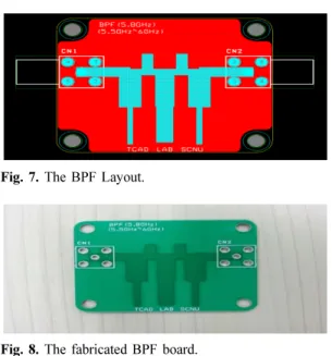
2.3. λg/2 Open-circuited stubs BPF 제작
기판 특성은 Table 4에 제시하였다. 회로도에 따라 Fig. 7에 레이아웃을 설계하였고 Fig. 8에 제작된 기판 을 나타내었다.
3. 5.8GHz 마이크로파 무선전력전송을 위한 BPF 측정
제작된 BPF를 이용하여 고조파 억제로 인해 전압이 증가하는지 측정하였다. 자체 제작한 RF-DC 변환기인
더블러로 입력전력 8 dBm ~ 12 dBm까지 측정하였으 며 Table 5에 나타내었다. BPF를 결합하기 전보다 결 합한 후가 출력전압이 더 높은 것을 알 수 있다. 고조 파 억제로 인해서 출력전압이 상승한 것을 알 수 있다.
4. 결 론
본 논문에서는 5.8 GHz 마이크로파 무선전력전송을 위한 BPF를 설계 제작하였다. λg/2 Open-circuited stubs BPF를 설계를 하고 T-shaped 전송선로를 이용해 2차와 3차 고조파를 억제하였다. RF-DC 변환기인 더 블러 결합을 통해 BPF의 고조파 억제로 인해 RF-DC 변환 전압이 상승함을 확인하였다.
참고문헌
1. C.-L. Hsu, F.-C. Hsu, J.-T. Kuo, “Microstip bandpass filters for ultra-wideband (UWB) wireless communi- Fig. 5. The BPF return loss for harmonics suppression.
Fig. 6. BPF performance for a harmonic suppression.
Table 4. The characteristics of PCB (FR4) board.
모델명 특성
TLY-5A 유전율(Er) 2.17
유전체 두께(H) 0.8 mm
Fig. 7. The BPF Layout.
Fig. 8. The fabricated BPF board.
Table 5. The BPF measurement for 5.8GHz microwave.
입력전력 (dBm)
BPF결합 안 된 Doubler 전압(V)
BPF 결합된Doubler 전압(V)
12 1.45 1.7
11 1.23 1.5
10 1.08 1.3
9 0.96 1.1
8 0.83 1
5.8 GHz 마이크로파 무선전력전송을 위한 BPF의 설계 및 구현 91
Journal of KSDT Vol. 14, No. 4, 2015 cations,” 2005 IEEE MTT-S International Microwave
Symposium Digest, pp. 679-682, (2005).
2. L. Ke, W. Wenping, Z. Lei, M. Xiaohan, “Microstrip bandstop filter using open stub and spurline,” 2011 IEEE International Conference on Microwave Tech- nology & Computational Electromagnetics (ICMTCE), pp. 223-236, (2011).
3. S. Srikanth and V. Jeyalakshmi, “Compact UWB micro strip band pass filter with open circuited stubs,”
Indian Journal of Science and Technology, 8(15), 58531, pp. 1-4, (2015).
4. Sun-Kuk Noh and Tae-Soon Yun “Quarter-wave- length stub bandpass filter with T-type inverter for harmonic suppressed application,” International
Journal of Control and Automation, 6(2), pp. 293- 301, (2013).
5. Ki-Cheol Yoon, Hee Nam, Fang Zhang, Hyun-Wook Lee, Tae-Ui Hong, and Jong-Chul Lee, “Design of a 5.8 GHz narrow band-pass filter with second har- monic suppression using the open stubs,” Proceed- ings of Asia-Pacific Microwave Conference, pp. 1-4, (2007).
6. J.-S. Hong, M. J. Lancaster, Microstrip filters for RF/
microwave applications, John Wiley & Sons, (2001).
접수일: 2015년 12월 2일, 심사일: 2015년 12월 14일, 게재확정일: 2015년 12월 21일