Development of reutilization system for Nuclear Power Plant Component using Object-Oriented Systems
Engineering Method
Tae Ho Yeo * , Tae Ryong Kim, Chang Lak Kim
*Kepco International Nuclear Graduate School
Abstract : The purpose of this study is to establish a component reutilization system in Nuclear Power Plant (NPP) by Object-Oriented Systems Engineering Method (OOSEM). Unified Modeling Language (UML) is mainly used for OOSEM. Operational Concept (OpsCon), Use cases, Structure Diagrams, and Behavior Diagrams are developed to analyze stakeholders needs, system requirements, logical architecture, and physical architecture. Based on the current decommissioning and purchasing system of the component, some activities from their systems were excepted and additional new activities were developed for a component reutilization system.
Key Words : Reutilization, NPP Component, OOSEM, UML, Class diagram
Received: August 22, 2016 / Revised: August 24, 2016 / Accepted: December 8, 2016
* Corresponding Author : Tae Ho Yeo, [email protected]
This is an Open-Access article distributed under the terms of the Creative Commons Attribution Non-Commercial
License(http://creativecommons.org/licenses/by-nc/3.0) which permits unrestricted non-commercial use, distribution,
and reproduction in any medium, provided the original work is properly cited.
1. Introduction
Kori unit 1 Nuclear Power Plant (NPP) is planned to be decommissioned in 2017 even though new reactor vessel head assembly and emergency diesel generator(EDG) were installed in 2013.
In the USA, San Onofre Nuclear Generating Station (SONGS) Units 2 and 3 also were permanently shutdown in 2012, just after the steam generator replacement in 2010 and 2011, respectively.
These unexpected shutdown of NPPs makes many components still worth using to be the waste.
Components are normally decommissioned by some proper processes; normally from detaching, pre-decontaminating, dismantling, post-decon- taminating, transporting, and finally disposal in Low Level Waste (LLW) disposal facility.
Nowadays, a study on recycling of the metal wastes generated from nuclear facilities was issued[1]. The study introduces the melt decon- tamination of decommissioning metal wastes as an effective recycling technology for the waste volume reduction. Even steam generator (SG) which is the biggest component and highly con- taminated can be partly recycled as clearance level (negligible radioactive level) ingots[2]. These studies define the recycling as the process in- cluding wastes melting and reusing of the materials.
Reutilization in this study, which differs from the recycling in previous studies[1][2], means reusing of the used components for their original functions. Reutilization is more economical than recycling because reutilization can not only reduce decommissioning cost for decommissioned NPP owner but also supply useful component for an urgent demand of other NPPs.
In case of sudden failure of a main component
in a NPP, reutilization of the component of the same type from a decommissioned NPP can be one of the options to solve the problem instead of shutting down the NPP and waiting for the new component fabrication. Actually, there was a real case in the USA. Davis-Besse NPP had to be urgently shut down with a serious problem at the reactor vessel head (RVH) in Feb. 2002.
FirstEnergy, Davis-Besse NPP owner, could replace the RVH in March 2004 by utilizing the unused, similar design head from the cancelled Midland plant. Considering that new RVH was manufactured and replaced in 2011, FirstEnergy could generate electricity for additional seven years by using RVH on the shelf, and save the revenue loss.
It is evident that each NPP has their specific components which are uncommon and therefore utilizing them is somewhat challengeable. It should, however, be noted that rare important components are not always supplied easily on time and this is the reason why demanders should consider a component reutilization.
On the other hand, reutilizable component owners who are encountered unexpected decom- missioning could have an option to reduce decommissioning cost exporting their useful com- ponents.
A component reutilization system which was developed from this study provides an alternative for both component demander and reutilizable component owner.
However, no reutilization system has been established for the reusable components from the decommissioned NPPs. The reutilization system consists of all activities and actors for the reutilization which defined before.
In this study, a development for the reutilization
Non-radioactive
Clean Component +Clearance level = 0
Limited Clearance Component +Clearance level < 10 µSv/y for individual dose +Clearance level < 1 man-Sv/y for collective dose of groups.
Radioactive*
+Effective dose limit after Decontamination: 50mSv/yr +Effective dose limit after Decontamination: 100mSv/5yrs Reutilizable Component
+Spec.;Size, Material, Weight +Performance +Operating Condition +Integrity
[Figure 1] Definition of a reutilizable component
system was conducted by Object Oriented Systems Engineering Method (OOSEM). Based on the current decommissioning and purchasing system of a component, some activities and actors from their systems were excepted and additional new activities and actors were developed for the establishment of the reutilization system.
2. Methodology
2.1 Scope
A component is an assembly of parts which performs independent functions such as pressure vessel, pump, piping, heat exchanger, etc.[3].
In this paper, a component is defined as Figure 1.
A component has its unique characteristics such as Specification, Performance, Operating Condition, and Integrity. A component can be classified as Non-radioactive or Radioactive according to its radioactivity. Currently, a component which is classified as Radioactive may not be allowed by the regulation.
Component reutilization in this study means that a component dismounted from a decom- missioned NPP can be reutilized in any other NPP, operating or under new construction.
Decommissioning system is previously described, and purchasing system for a component normally falls into three categories: <Supply>, <Install>,
and <Inspection>. Firstly, a component may be supplied by a vendor and then installed in a NPP. After installation, component inspection is done by inspectors. Decommissioning system and purchasing system are illustrated in Figure 5 as packages.
In this study, some activities for the com- ponent reutilization will be adopted from the decommissioning and purchasing systems. Un- necessary activities such as dismantle, dispose, and supply are excepted. Additionally, a new activity is developed for the component reutiliza- tion.
2.2 Assumption
Reutilization of radioactivated components such as steam generator, reactor coolant pump, and fuel handler are assumed to be allowed in this paper though current regulation does not clearly allow it. All things related to a radio- activated component are star marked in all Unified Modeling Language (UML) diagrams of this paper.
A reutilizable component is assumed to be prepared by decommissioned NPP owner waiting for a requirement from a demander who wants to use the component.
All actors in UML diagrams are assumed to have abilities for their activities. For example, transporter is assumed to have an avaliable transportation for the reutilizable component.
2.3 OOSEM
OOSEM integrates object-oriented concepts
with model-based and traditional SE methods
to help architect flexible and extensible systems
that accommodate evolving technologies and
changing requirements. Object-oriented concepts
[Figure 2] OOSEM activities [4]
that are leveraged in OOSEM include classes in UML and objects, along with the concepts of encapsulation and inheritance[4]. OOSEM activities are illustrated in Figure 2; upper four activities and lower Validate & Verify (V&V) subactivity were described in chapter 2.5. As a test case for V&V, polar crane utilization system was developed. Polar crane can be a representative test case because it is a Non-radioactive com- ponent, so that there is no current regulation issue regarding radioactive control.
2.4 UML
In the 1990s, a new modeling language that incorporated object-oriented concept was formalized:
the UML[5]. UML 2 provides system designers with 14 different diagrams to show different system characteristics. They are divided into two groups: Structural Diagrams and Behavior Diagrams. Structural Diagrams show the static structure of the objects in a system. That is, they depict those elements in a specification that are irrespective of time. On the other hand, behavior diagrams show the dynamic behavior of the objects in a system, including their methods, collaborations, activities, and state histories.
The dynamic behavior of a system can be de- scribed as a series of changes to the system over time.
In this study, following UML 2 diagrams were used; Class, Component, Deployment, Activity, Use Case, State Machine, and Sequence diagrams.
All diagrams are developed by StarUML Ver. 2.7.0 which applies UML 2.
2.5 OOSEM using UML
OOSEM proceeded through following 5 steps.
2.5.1 Step 1: Analyze Stakeholder Needs This activity supports analysis of both the
“as-is” and the “to-be” enterprise. OOSEM specifies the mission requirements for the
“to-be” enterprise to reflect customer and other stakeholder needs. This paper developed Operational Concept (OpsCon) and Mission Use Case in this step. OpsCon is an Operational Concept articulates a vision for what the system is, a statement of mission requirements, and a description of how the system will be used.
2.5.2 Step 2: Analyze System Requirements This activity specifies the system requirements that support the mission requirements. This paper developed System Use Case and Capability in this step. Capability is the ability to achieve a desired effect under specified performance standards and conditions through combinations of ways and means activities and resources to perform a set of activities. The Operational Concept and the Use Cases require Capabilities in order to be implementable.
2.5.3 Step 3: Define Logical Architecture
This activity includes decomposing and par-
titioning the system into logical elements. This
paper developed Structural and Behavior Diagrams
such as Class Diagram, Activity Diagram, Sequence
Old Owner New Owner
Regulator Component Reutilization
Reutilizable component Required component
Requlate reutilization
[Figure 4] Mission Use Case
Diagram, and State machine Diagram in this step.
2.5.4 Step 4: Synthesize Candidate Physical Architectures
Logical elements are allocated to physical elements. This paper developed Component Diagram and Deployment Diagram in this step.
2.5.5 Step 5: Validate and Verify System As one of the common subactivities, this activity verifies that the system design satisfies its requirements and validates that those requirements meet the stakeholder needs.
As previously described before, polar crane was chosen for a test case. Class Diagram of a polar crane in Figure 14 is a representative reutilization system design and Use Case in Figure 5 is the requirements of the system.
Operational Concept in Figure 3 is the stake- holder needs for the validation.
2.6 Limitation
Since the reutilization of radioactivated component has not been tried by nuclear industry, there is no prior reference. However, this study includes reutilization of radioactivated components because of their potential benefits. Alternatively, existing regulations for safety such as the effective dose limit for radiation workers are considered.
Though the main issue of the component reutilization is the cost benefit, actual cal- culation is excluded from this study. Studying the cost estimates of NPP plants, it was clear that there is no standard methodology for cat- egorizing the costs of decommissioning. Also, publically available decommissioning cost infor- mation for some plants does not include a break- down of the costs, and even the breakdown of
costs is considered to be confidential[6].
3. Developments and Results
3.1 Step 1: Analyze Stakeholder Needs In this step, OpsCon and Mission Use Case are developed as Figure 3 and 4, respectively.
[Figure 3] Operational Concept
OpsCon is described as follows;
∙ Decommissioned plant owner (Old Owner) wants to reduce decommissioning work exporting reutilizable components.
∙ Demander (New Owner) wants to reduce purchase work importing the required com- ponent.
∙ The regulator checks the safety of the reutilization system.
∙ The component to be reutilized is detached,
Purchase Decommissioning
Old Owner
Decommissioner
Detach
Decontaminate
Dismantle
Transporter Transport
LLW Disposal Facility Manager
Dispose in LLW Disposal Facility Keep
Reutilization
New Owner Supplier
Inspector Supply
Install
Inspect
<<include>>
<<include>>
<<include>>
<<include>>
When Install is not ready
<<extend>>
Regulator
*
<<extend>>
[Figure 5] System Use Case
Reutilization System<<Capability>>
Purchase
<<Capability>>
Reutilization Applicability Check
<<Capability>>
Performance Check
<<Capability>>
Operating Condition Check
<<Capability>>
Integrity Check
<<Capability>>
Regulation Check
<<Capability>>
Decommissioning
<<Capability>>
Detaching
<<Capability>>
Decontaminating*
<<Capability>>
Transporting
<<Capability>>
Inspecting
<<Capability>>
Installing
<<Capability>> Radiation handling*
<<Capability>>
Keeping
<<Capability>>
[Figure 6] Capability
decontaminated, and transported from the old owner, installed and inspected in the new owner.
Figure 4 shows there are three main actors who interact with the component reutilization system. Old owner supply a reutilizable component, New owner demands a required component, and Regulator checks whole reutilization process.
Detailed component reutilization system functions are described in the System Use Case.
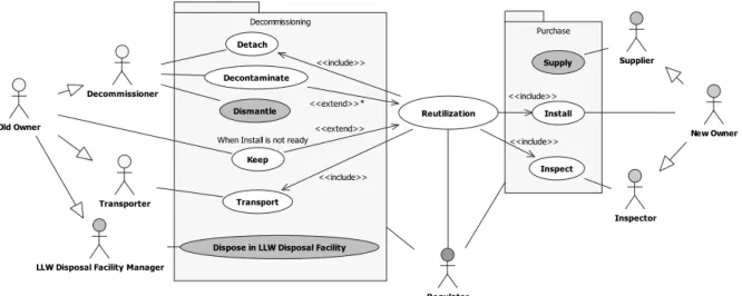
3.2 Step 2: Analyze System Requirements In this step, System Use Case and Capability are developed as Figure 5 and 6, respectively.
Component reutilization system includes <Detach>
and <Transport> from Decommissioning system.
<Decontaminate> extends to the component reutilization system when the reutilizable com- ponent is radioactivated and <Keep> extends to the component reutilization system when Install is not ready. Component reutilization system also includes <Install> and <Inspection>
from Purchase. Decommissioner and Transporter are Sub-actors of Old Owner and Inspector is
a sub-actor of New Owner. Old Owner, New Owner, Regulator, and all Sub-actors are classes in Step 3 Class Diagram.
Capability shows the ability to achieve a component reutilization. Basically, there are three capabilities; reutilization applicability check, decommissioning, and purchase. Radiation handling works when the reutilizable component is radio- active. All capabilities are matched with System Use Case and OpsCon.
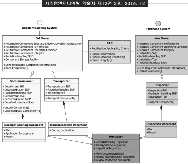
3.3 Step 3: Define Logical Architecture
Class, Activity, Sequence, and State Machine
Diagrams are developed in this step as Figure
7, 8, 9, and 10, respectively.
RAC
+Reutilization Applicability Criteria +Check Performance() +Check Operating Condition() +Check Integrity()
Inspector +Inspection Skill +Radiation handling Skill*
+Inspection Tool +Inspect Component()
Regulator +Decommissioning Regulation +Transportation Regulation +Inspection Regulation +Allow Decommissioning() +Review Transportation document() +Review Inspection document()
New Owner +Required Component Performance +Required Component Operating Condition +Required Component Integrity +Installation Skill
+Radiation handling Skill*
+Installation Tool +Installed Interface Spec.
+Send Required Component Information() +Install Component()
Decommissioning System Purchase System
Old Owner
+Reutilizable Component Spec.;Size,Material,Weight,Radioactivity +Reutilizable Component Performance
+Reutilizable Component Operating Condition +Reutilizable Component Integrity +Radiation handling Skill*
+Component Storage Facility
+Send Reutilizable Component Information() +Keep Component()
Decommissioner +Detachment Skill +Decontamination Skill*
+Radiation handling Skill*
+Detachment Tool +Decontamination Tool*
+Detached Interface Spec.
+Detach Component() +Decontaminate Component*()
Transporter +Transportation Skill +Radiation handling Skill*
+Transportation +Transport Component()
Decommissioning Document +Plan
+Application for approval +Report
Transporatation Document +Carring declaration
Inspection Document +Plan
+Report
[Figure 7] Class Diagram
In Figure 7, Old Owner sends a reutilizable component characteristics such as specification, performance, operating condition, and integrity to a reutilization applicability checker (RAC).
RAC checks the applicability comparing with a reutilizable component characteristics and required component characteristics. Old Owner keeps a reutilizable component in a Component Storage Facility until the install is ready. Decommissioner detaches a reutilizable component and decon- taminate when the reutilizable component is radioactive. Transporter moves a reutilizable component to the New Owner’s NPP. New Owner installs and Inspector inspects the com- ponent. Decommissioner, Transporter, New Owner, Inspector have their own skills and tools to
perform their work successfully. Classes need radiation skill for a radioactive component. Regu- lator reviews Decommissioning, Transportation, and Inspection Documents which are submitted by Decommissioner, Transporter, and Inspector according to the regulation.
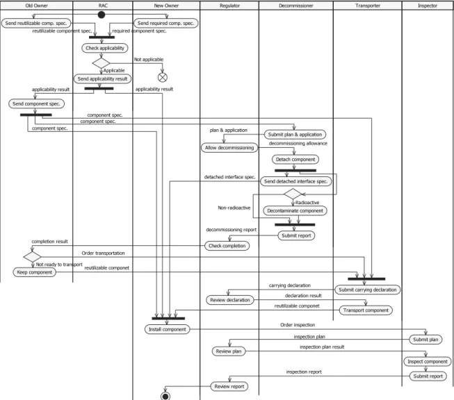
Figure 8 shows an Activity Diagram of a
component reutilization system. Each swim lane
represents a class in the Class Diagram. When
the reutilization is applicable, the Old Owner
sends a reutilizable component specification to
the New Owner, Decommissioner, and Transporter
to conduct their work. After the component
detach, Decommissioner sends the detached
interface specification to New Owner so that a
reutilizable component is installed. Regulator
Old Owner RAC New Owner Regulator Decommissioner Transporter Inspector
Send reutilizable comp. spec. Send required comp. spec.
Check applicability
reutilizable component spec. required component spec.
Send applicability result Applicable
Send component spec.
Detach component
Decontaminate component
Transport component
Install component
Inspect component Radioactive
Non-radioactive Not applicable
Keep component
Not ready to transportreutilizable componet Order transportation
reutilizable componet Send detached interface spec.
Submit plan & application Allow decommissioning
applicability result
plan & application component spec.
decommissioning allowance
detached interface spec.
component spec.
component spec.
Submit report Check completion
decommissioning report completion result
Submit carrying declaration Review declaration
carrying declaration declaration result
Order inspection
Submit plan
Submit report Review plan
Review report
inspection plan inspection plan result
inspection report applicability result
[Figure 8] Activity Diagram
allows decommissioning reviewing the plan &
application documents and checks the decom- missioning completion reviewing the report.
Inspector submits the plan and report to the regulator before and after the inspection.
In Figure 9, Sequence Diagram, Each lifeline shows an instance of the Classes and cor- responds to the swim lanes of the activity diagram.
The sequence of message exchange matches those shown on the Activity Diagram. This sequence represents a radioactive component reutilization.
Figure 10 shows a State Machine Diagram
of Decommissioner. This shows the behavior of Decommissioner following the activities and arrival and sending of messages in a swim lane of the Activity Diagram.
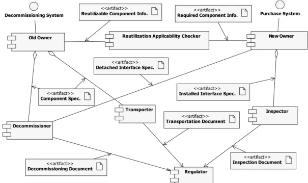
3.4 Step 4: Synthesize Candidate Physical Architectures
In Figure 11, physical components and their
relationships are shown. Each component rep-
resents a class in the Class Diagram. An artifact
is the specification of a physical piece of in-
formation that is sent and received between
related components.
: Old Owner : RAC : New Owner
: Regulator : Decommissioner : Transporter
: Inspector 1 : Send reutilizable comp. spec.()
2 : Send required comp. spec.()
3 : Check applicability()
4 : Send applicability result()
5 : Send comp. spec.() 6 : Send comp. spec.() 7 : Send comp. spec.()
8 : Submit plan & application()
9 : Allow decommissioning()
10 : Detach comp.()
11 : Send detached interface spec.()
12 : Decontaminate Comp.*()
13 : Submit report() 14 : Check completion()
15 : Order Transportation()
16 : Submit carrying declaration()
17 : Review declaration()
18 : Transport comp.()
19 : Install comp.()
20 : Order inspection()
21 : Submit plan()
22 : Review plan()
23 : Inspect Comp.()
24 : Submit report() 25 : Review report()
[Figure 9] Sequence Diagram
Waiting for Decommissioning allowance
Ready to send Detached interface spec.
Component Spec. arrived/Submit plan & application
Decommissioning allowance arrived/Detach component
Require interface spec. to install/Send interface spec.
Waiting for Decontamination Radioactive component*
Prepare Detached interface spec. Check component radioactivity
Require Decontamination/Decontaminate component*
Non-radioactive component
Submit Decommissioning completion report Waiting for radiation level check
Radiation level check*
Satisfy radiation level Dissatisfy radiation level
[Figure 10] State Machine Diagram of Decommissioner
Old Owner
Regulator
Reutilization Applicability Checker New Owner
Decommissioning Document
<<artifact>>
Decommissioner
Transporter Inspector
Transportation Document
<<artifact>>
Inspection Document
<<artifact>>
Decommissioning System Purchase System
Component Spec.
<<artifact>>
Reutilizable Component Info.
<<artifact>>
Required Component Info.
<<artifact>>
Detached Interface Spec.
<<artifact>>
Installed Interface Spec.
<<artifact>>
[Figure 11] Component Diagram
Old Plant Old Owner
Decommissioner
Transporter Old Owner
Decommissioner
Transporter
New Plant New Owner
Inspector Reutilization Applicability Checker
New Owner
Inspector Reutilization Applicability Checker
Regulator Component Spec.<<artifact>>
Reutilizable Component Info.<<artifact>>
Required Component Info.<<artifact>>
Installed Interface Spec.
<<artifact>>
Detached Interface Spec.
<<artifact>>
Decommissioning Document<<artifact>>
Transportation Document<<artifact>>
Applicability Result<<artifact>>
Inspection Document
<<artifact>>
Decommissioning Review<<artifact>>
Transportation Review<<artifact>>
Inspection Review<<artifact>>
[Figure 12] Deployment Diagram
Old Plant Old Owner Old Owner
New Plant New Owner New Owner
Reutilization System
Transporter
Decommissioner
Inspector Reutilization Applicability Checker
Transporter
Decommissioner
Inspector Reutilization Applicability Checker
Regulator Reutilizable Component Info.
<<artifact>>
Component Spec.<<artifact>>
Required Component Info.<<artifact>>
Installed Interface Spec.<<artifact>>
Applicability Result<<artifact>> Detached Interface Spec.<<artifact>>
Decommissioning Document<<artifact>>
Transportation Document
<<artifact>>
Inspection Document
<<artifact>>
Decommissioning Review
<<artifact>>
Transportation Review
<<artifact>>
Inspection Review
<<artifact>>
[Figure 13] Alternative Deployment Diagram
Figure 12 shows a Deployment Diagram. This Diagram indicates the New Plant checks the reutilization applicability. Old Plant and New Plant control a component reutilization process directly. This reutilization system is easily adopted when the component reutilization is not familiar.
Alternative Deployment Diagram is shown in Figure 13. As an independent node, reutilization
system directs whole component reutilization process. This alternative reutilization system may be developed when the component reutilization business is brisk.
3.5 Step 5: Validate and Verify System
Figure 14 shows a Class Diagram of a polar
crane (PC) which is developed to verify the
Old Owner_PC
+Component Storage Facility +Send Utilizable PC Info.() +Keep PC()
New Owner_PC
+Installation Std.: KEPIC MIA-4400 +Installation Skill
+Installation Tool +Send Required PC Info.() +Install PC() Reutilization Applicability Checker_PC
+Std.: KEPIC MIA-4000 +Check Performance() +Check Operating Condition() +Check Integrity()
Decommissioner_PC +Detachment Skill +Detachment Tool +Detach PC()
Transporter_PC
+Transportation Skill +Transportation +Transport PC()
Inspector_PC +Installation Std.: KEPIC MIA-4500 +Inspection Skill
+Inspection Tool +Inspect PC()
Decommissioning Document_PC
+Plan
+Application for approval +Report
Transportation Document_PC +Carring declaration
Inspection Document_PC +Plan
+Report Decommissioning System_PC
Purchase System_PC
if not applicable
if not applicable
PC Spec.
PC Spec. Installed Interface Spec.
Regulator_PC +Decommissioning
+Transportation +Inspection
+Allow Decommissioning() +Check Decommissioning Completion() +Review Transportation document() +Review Inspection document() Reutilizable PC Info.
+Spec.: Size,Weight,Span rail, Crane rail +Performance: Construction/Maintenance load (ton) +Operating Condition: Dome Dia./height (meter) +Integrity: AMP,TLAA
Required PC Info.
+Performance: Construction/Maintenance load (ton) +Operating Condition: Dome Dia./height (meter) +Integrity: AMP,TLAA
Applicability Result Applicability Result
Detached Interface Spec.
+Span rail