Kumoh National Institute of Technology
Abstract
In this paper, we present a design for a retraction-type actuator (ReACT) that has the characteristics of both thermomechanical metamaterials and displacement amplification mechanisms. The ReACT consists of an actuating bar, a diamond-shaped displacement amplification (DA) structure, and a slot for loading thin-film heaters formed through the actuating bar. When power is supplied to the thin film heater, the actuating bars contacting the heater thermally expand, and the diamond-shaped DA structures retract in the longitudinal direction. The performance characteristics of the ReACT, such as temperature distribution and retracting displacement, were calculated with thermomechanical analysis methods using the finite element method (FEM). Subsequently, the ReACTs were fabricated using a polymer- based 3D printer that can easily execute complex structures, and the performance of the ReACT was evaluated through repeated tests under various temperature conditions. The results of the performance evaluation were compared with the results of the FEM analysis.
Key Words: Displacement amplification, Linear actuator, Metamaterial
1. Introduction
Conventional aircrafts control the attitude by moving the flaps at the rear of the wings and the flaps are primarily driven with electric or hydraulic/pneumatic actuators. Electric actuators using a motor require a battery as the energy storage device as well as a speed reduction mechanism to amplify the operating force. This makes the system highly complex and increases its size and weight. Hydraulic/pneumatic actuation systems consist of a hydraulic/pneumatic tank as the energy storage system and also compressors, valves, sensors, and piping, thus making these systems more complex than electric drive systems and increasing their size and weight. As a result, while these actuators can be used in large systems such as medium-to-large aircrafts, it is difficult to apply them to small systems with demanding space or weight constraints, such as ultra-small unmanned aircraft.
In contrast, in artificial muscle actuators, which do not use motors or hydraulic/pneumatic systems, the structure itself contracts or relaxes like a human muscle when electric power
is applied. Artificial muscle actuators have simpler structures than those of electric and hydraulic/pneumatic actuators, and the structure itself contracts and relaxes during operation.
Hence, they do not require additional structures or gears, links, screws, or piping, for power transmission, thus making them small and lightweight. Artificial muscle actuators are, therefore, suitable for the morphing structure of an ultra-small unmanned aircraft.
This study focuses on the application of a displacement amplification mechanism based on mechanical metamaterials, which have recently been extensively studied to develop an artificial muscle actuator that can be applied to a morphing wing for ultra-small unmanned aircraft [1]. Mechanical metamaterials refer to materials artificially designed to have properties not found in nature [2]. Most mechanical metamaterials are created using common materials such as metal or plastic, and by regularly arranging the geometric pattern of the structure. Therefore, they can be designed to have properties completely different from those of materials found in nature. In this way, mechanical metamaterials with a negative Poisson's ratio [3-5], negative thermal expansion [6- 8], and negative compression ratio [9-11] can be fabricated.
Most previous researches on mechanical metamaterials involved adjusting mechanical properties such as Poisson's Received: Oct. 23, 2019 Revised: Feb. 11, 2020 Accepted: Mar. 10, 2020
† Corresponding Author
Tel: +82-53-600-5350, E-mail: [email protected]
Ⓒ The Society for Aerospace System Engineering
ratio, thermal expansion coefficient, elastic modulus, and compression ratio through geometric structure and pattern design inside the metamaterial [12,13] while they did not pursue their use as actuators. Recent studies have investigated the application of mechanical metamaterials for morphing structures or soft robots. The origami-type morphing metamaterial [14] is one of the actuator types using mechanical metamaterials, in which a film two-dimensional pattern is designed and then transformed into a three- dimensional structure. However, due to its weak stiffness in the out-of-plane direction, this film-type actuator is unsuitable for structure actuators that must provide support the morphing wing for an unmanned aircraft. Thus, research on artificial muscle actuators consisting of mechanical metamaterials that can operate in one axial direction while withstanding external aerodynamic loads is required.
In this paper, we propose a design for a ReACT with the characteristics of thermomechanical metamaterials that retract in the axial direction when heat is applied locally. A diamond- type displacement amplification mechanism, which has been extensively studied [15], has been applied to implement a linear actuator. It can withstand external loads and have a much greater actuating displacement than that of simple thermal expansion. The ReACT has a very complex structure in which 10 unit actuators comprising the displacement amplification structure and an actuating bar made of the same material are connected in series. It retracts in the axial direction when heated by the application of electricity to the thin film heater inserted in the inner slot. The performance of the ReACT (e.g., actuating
Fig. 2 Kinematic model of ReACT.
displacement) was predicted with thermal structure analysis using the finite element method (FEM) analysis. The ReACT was then fabricated using a selective laser sintering (SLS) 3D printer, and its performance was evaluated. The performance measured experimentally was compared to the performance predicted from FEM analysis. .
2. ReACT design
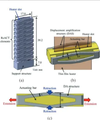
As shown in Fig. 1(a), the ReACT consists of 10 unit actuators connected in series. The thin film heater can be inserted in a slot inside the structure. The ReACT has a total length of 38.2 mm, a width of 17 mm, and a thickness of 7 mm.
Figs. 1(b) and (c) are schematics of the unit actuator shape and actuation mechanism. The unit actuator consists of an actuating bar, displacement amplification structure (DAS), and thin-film heater. As shown in Fig. 1(b), the thin-film heater is inserted through the center of the actuator. Fig. 1(c) shows the actuation mechanism of the ReACT. When the inner actuating bar is heated using the thin film heater, the actuating bar thermally expands in the transverse direction. Therefore, the external diamond-shaped DAS retracts in the axial direction.
The structure is design to increase the time of heat transfer from the thin film heater to the external DAS by placing the actuating bar on the inside and minimizing the gap between each unit actuator. Fig. 2(a) shows a schematic diagram of the shape of the actuator. The transverse length l increases by Δl in response to the thermal expansion of the actuating bar. Here, as shown in Fig. 2(b), the displacement amplification bar AB undergoes rigid-body rotation, and its length increases due to an elastic deformation. Accordingly, points A and B move
(a) (b)
(c)
Fig. 1 Schematics of retraction-type actuator (ReACT).
toward points A' and B', respectively. Here, the ratio of the axial retraction displacement (Δh) and the transverse movement distance (Δl) is referred to the amplification ratio. It can be calculated using Equation (1), according to a previous report [15].
2 cos
cos cos sin
6 sin
a a a
l h
l t l
l
(1)
In Equation (1), l a and t indicate the initial length and thickness of bar AB. Equation (2) more concisely expresses Equation (1).
2
2 6 2
cot 6 tan
a a
l h
l t l
(2)
It is observed that the actuator thermally expands in the transverse direction and retracts in the axial direction with the amplified displacement in Equation (2). Here, the amplification ratio of the axial retraction displacement to the transverse thermal expansion length increases as θ decreases.
Thus, smaller θ makes larger amplification ratio. However, since the heating section of the heater used in this study is approximately 40 mm, the ReACT was designed for each of the 10 unit actuators to have a length (H) of 4 mm or less, as shown in Table 1.
3. FEM analysis
We conducted a numerical analysis using the FEM analysis tool to examine the actuator temperature distribution and thermal expansion characteristics caused by heating with the thin film heater. It was assumed that all heat generated by the heater was transferred to the actuator. Table 2 shows the physical property values of the Duraform PA (Nylon 6) used to manufacture the actuator. Heat loss from the actuator surface is assumed to occur by natural convection. It is equal to heat
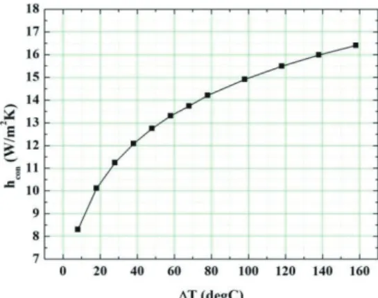
Fig. 3 Convective heat transfer coefficient as a function of ΔT.
The convective heat transfer coefficient of natural convection is determined by the temperature of the surface. It is calculated using the Nusselt number below [17]:
0.54 L1/4
Nu Ra (3)
where Ra is the Rayleigh number and is expressed as follows [17]:
3 2
2
( ) ( )
Pr s c s c
L L g T T L g T T L
Ra Gr
(4)
where Gr is the Grashof number, Pr is the Prandtl number, g is gravitational acceleration, β is the volume expansion coefficient, Ts is the actuator surface temperature, T∞ is the ambient temperature, Lc is the characteristic length, ν is the kinematic viscosity, and α is the thermal diffusivity. All property values were used for the film temperature of the actuator surface temperature and ambient temperature.
Assuming that air is an ideal gas, the inverse of the absolute air temperature was used for the volume expansion coefficient.
The convective heat transfer coefficient hcon can be calculated using Equation (5).
con air
c
h Nu k L
(5)
Fig. 3 shows the convective heat transfer coefficient calculated using Equation (5). At low surface temperatures similar to the ambient temperature, the convection heat transfer coefficient is small. However, at high surface temperatures, the difference in temperature increases, resulting in a large convection heat transfer coefficient. The convective heat transfer coefficient values of Fig. 3 were entered into the commercial program ANSYS to calculate the temperature distribution and actuating displacement within the actuator for times up to 120 s.
Thermal conductivity (k) 0.243 W/m·K Coefficient of thermal
expansion (α)
22–50 °C 6.67×10⁻⁵ /℃
above 50 °C 14.9×10⁻⁵ /℃
Fig. 4 ReACT fabricated with 3D printer.
loss for a hot horizontally flat plate.
Fig. 5 Experimental setup for performance evaluation of ReACT.
4. Fabrication and performance test
Since the ReACT has a very complex structure in which 10 unit actuators comprising the DAS and actuating bar are connected in series, it is challenging to fabricate it using general machining methods. Therefore, it was fabricated using a selective laser sintering 3D printer (ProX 500 Plus, 3D SYSTEMS Inc.), which can easily generate complex structures. Polyamide (Duraform PA, Nylon 6) was used as the substrate material. The ReACT performs actuation by inserting a thin-film heater into a slot formed on the inside and then applying electricity for heating. Fig. 4 shows the completely fabricated ReACT. Despite its highly complex structure, it was successfully fabricated as designed. In particular, the proposed actuator can be manufactured at a very low cost relative to actuators that use expensive materials, such as conventional piezoelectric materials.
Fig. 5 shows the schematic diagram of the ReACT performance test equipment. As shown in the bottom-left photo of Fig. 5, two thin-film heaters are inserted into the slot inside the ReACT, and a thin film thermocouple for measuring
(a) (b)
Fig. 6 FEM analysis results: (a) temperature distribution and (b) retraction displacement at 4 V.
(a) (b)
Fig. 7 FEM analysis results: (a) temperature distribution and (b) retraction displacement at 6 V.
Fig. 8 FEM analysis results: (a) temperature distribution and (b) retraction displacement at 7 V.
Fig. 9 Time lapse images for retraction motion of ReACT at 7 V.
the temperature is inserted between the heaters. For this task, a general thin-film heater (K05711980-A, WATLOW) with a metal resistor formed on a polyimide film was used. For the support structure, the ReACT was attached to a base plate using polyimide tape, and the opposite moving end was configured to move freely.
After supplying voltages of 4, 6, and 7 V to the heater with a power supply (OPE-303QI, ODA), the change in length (△h) was measured by using a CCD microscope (AM7013MZT, Dino) to capture images every 10 s for 2 min.
As shown in the bottom-right photo of Fig. 5, after photographing the fine ruler printed on the transparent acrylic plate, Δh could be accurately measured using image processing software.
5. Results and discussion
Figs. 6, 7, and 8 show the results from FEM numerical analysis of the temperature distribution and retraction displacement after 120 s, with input voltages of 4, 6, and 7 V, respectively. The temperature distribution shows that, although the temperature of the inner actuating bar increased after 120 s, the temperature of the external DAS barely increased. This indicates that the thermal insulation of the ReACT was designed properly so that the DAS length (la) should not increase due to heating. The retraction displacement results demonstrate the properties of the thermomechanical metamaterials, which cause the length to decrease in the axial direction as the temperature increases. Fig. 8 shows that, when heated for 120 s at an input voltage of 7 V, the ReACT end retracts by up to 1.77 mm. This value is amplified to approximately 5.3 times the thermal expansion change in length (approximately 0.34 mm) calculated when ΔT is 110 °C, assuming that the actuator shape is that of a simple square bar.
Fig. 9 shows CCD microscope images of the ReACT end at various times and with an input voltage of 7 V. As in the FEM numerical analysis results when the ReACT is heated, the properties of the thermomechanical metamaterials into which the ReACT retracts can be observed. After photographing a fine ruler printed on transparent acrylic, image processing
Fig. 10 Comparison of internal temperatures obtained experimentally and with FEM analysis.
software was used to measure the retraction displacement of the ReACT end.
Fig. 10 contains a plot of temperature versus time calculated with FEM analysis and measured experimentally with a thermocouple inserted between the two thin-film heaters, with input voltages of 4, 6, and 7 V. The temperatures were measured three times, after which the mean and standard deviation were calculated (Fig. 10). Since the resistance of the thin-film heater is approximately 40 Ω, power of 0.40, 0.90, and 1.2 W was supplied to the heaters at input voltages of 4, 6, and 7 V. Fig. 10 shows that the temperature increases in proportion to the power supplied to the heater. Thus, when the power of 0.40 W (4 V) was supplied, temperatures of 25.0, 34.0, and 39.0 °C were measured by the thermocouple after 40, 80, and 120 s, respectively. At 0.90 W (6 V), and after 40, 80, and 120 s, temperatures measured 54.3, 72.3, and 83.3 °C, and, at 1.2 W (7 V), temperatures measured 72.3, 96.3, and 109.7 °C. Furthermore, the internal temperature increased exponentially with increased heating time. As shown in Fig. 11, the ReACT consists of a structure in which two heaters are inserted between the actuating bars made of polyamide. A thermocouple for measuring the temperature is located between the two heaters. In a semi-infinite structure, the heat flux and surface temperature over time can generally be calculated with Equation (6).
s 4
S i q
T T
k
(6)
Here Ts is the heater surface temperature, and Ti is the heater initial temperature, and qs k, α, and τ are the heat flux generated by the heater, thermal conductivity of the actuating bar, thermal diffusivity, and time, respectively. Equation (6) shows that the heater surface temperature Ts is proportional to the heat flux qsand increases exponentially with increasing time τ. These characteristics are also shown in the FEM
Fig. 11 Schematic cross section of ReACT indicating where the heaters and thermocouple are loaded.
Fig. 12 Retraction displacement of ReACT as a function of time.
analysis results of Fig. 10.
Fig. 12 contains a graph comparing the retraction displacement at the ReACT end measured experimentally and the retraction displacement calculated with FEM analysis at each input voltage. As with the change in temperature over time (Fig. 10), the actuating displacement also changes exponentially. While the experimental and FEM analysis results were similar with input voltages of 6 V and 7 V, they differed somewhat at 4 V. This is because, in the FEM analysis, the study assumed that the heat flux corresponding to the power supply is directly applied to the surface of the slot in which the heaters are inserted. However, Fig. 11 shows that, in the actual experiment, there was a gap between the thin film heater and the slot, causing a heat-resistant layer to form between the heater and the actuating bar. When a heat-resistant layer is formed, the temperature of the actuating bar is lower than that predicted with the FEM analysis. In particular, when the voltage is small, the impact of the heat-resistant layer exceeds that of the heat flux generated by the heater, causing a significant difference between the experimental and FEM analysis results.
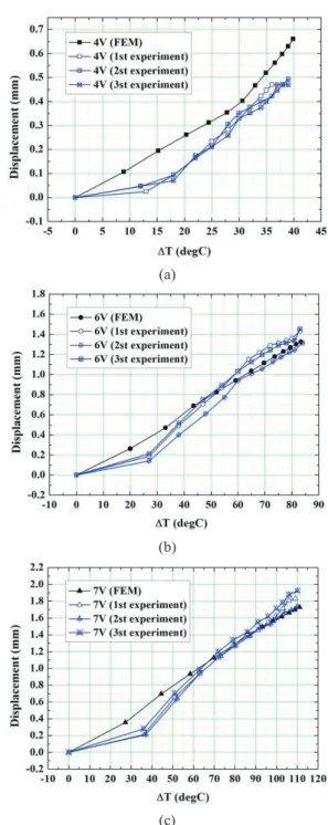
Figure 13 contains a plot of the retraction displacement versus the temperature of the thin-film heater. At an input voltage of 4 V, the experimental values were smaller than were the FEM analysis values for all sections, which is attributed to the aforementioned heat-resistant layer between the heater and
(a)
(b)
Fig. 13 Displacement of ReACT as a function of (c) temperature at excitation voltages of (a) 4 V, (b) 6 V, and (c) 7 V.
actuating bar. At input voltages of 6 V and 7 V, the experimental values were smaller than the FEM analysis results in the low-temperature section. This phenomenon is also attributed to the heat-resistant layer. Conversely, in the high-temperature section, the experimental and FEM analysis results were generally similar; however, at ΔT of 60-70 °C or higher, the experimental values were sometimes larger. This is attributed to variations in environmental factors such as
Herein, we presented a design for a ReACT that has the characteristics of both thermomechanical materials, in which retraction occurs in the axial direction when heated by thin- film heaters inserted in the inside slot and displacement amplification in which deformation is amplified several times relative to that from simple thermal deformation. The ReACT consists of actuating bars and a diamond-shaped DAS, and, by arranging 10 unit actuators in series, we were able to implement an actuator with an actuating displacement of several mm. The ReACT exhibits a highly complex structure, and a selective laser sintering 3D printer was required for fabrication, and polyamide was used as the fabrication material. Polyamide has a high thermal expansion coefficient and operating temperature higher than those found for other polymer materials.
The natural convection heat transfer coefficient as a function of temperature was calculated and used for the FEM analysis, through which the internal temperature distribution was calculated. By analyzing the thermal structure using the internal temperature distribution data, the actuating displacement versus input voltage and temperature in the transient condition were calculated.
After applying voltages of 4, 6, and 7 V to the heater of the ReACT, the changes in length (△h) were measured for 2 min (at 10-s intervals) using a CCD microscope and image processing software. The comparison of the experimental data and FEM analysis results showed that the heater temperatures were very similar. At an input voltage of 4 V, however, differences were observed in the experimental and FEM analysis retraction data. This difference is attributed to the formation of a heat-resistant layer resulting from the gap between the heater and the actuator. With input voltages of 6 V and 7 V, the experimental and FEM analysis plots of retraction displacement versus time were similar. Although the FEM results for retraction displacement were higher than the experiment results in the low-temperature region, the results in the high-temperature region were similar. This is because, in the low-temperature region, a heat-resistance layer forms between the heater and actuating bar, causing the experimental and FEM results to differ. Furthermore, as the temperature increases, the impact of the heat resistance becomes small relative to that of the heat flux generated in the heater, thus leading to similar characteristics for the FEM and
This study was conducted with the support of the Korea Science and Engineering Foundation through the funding of the Ministry of Education, Science, and Technology in 2019 (NRF-2017R1C1B5018039).
References
[1] S. Barbarino, O. Bilgen, R.M. Ajaj, M.J. Friswell, D.J.
Inman, "A Review of Morphing Aircraft," Journal of Intelligent Material Systems and Structures, vol. 22, pp.
823-877, 2011.
[2] J. U. Surjadi, L. Gao, H. Du, X. Li, X. Xiong, N. Fang, Y.
Lu, "Mechanical Metamaterials and Their Engineering Applications," Advanced Engineering Materials, vol. 21, p. 1800864, 2019.
[3] R. Lakes, "Foam Structures with a Negative Poisson's Ratio," Science, vol. 235, no. 4792, pp. 1038–1040, 1987.
[4] K. E. Evans and A. Alderson, "Auxetic Materials:
Functional Materials and Structures from Lateral Thinking," Adv. Mater., vol. 12, no. 9, pp. 617–628, 2000.
[5] H. Mitschke, J. Schwerdtfeger, F. Schury, M. Stingl, C.
Korner, R.F. Singer, V. Robins, K. Meche, G.E. Shroder- Turk, "Finding Auxetic Frameworks In Periodic Tessellations," Adv. Mater., vol. 23, no. 22–23, pp. 2669–
2674, 2011.
[6] R. Lakes, "Cellular Solid Structures with Unbounded Thermal Expansion," J. Mater. Sci. Lett., 15(6), pp. 475–
477, 1996.
[7] O. Sigmund and S. Torquato, "Composites with Extremal Thermal Expansion Coefficients," Appl. Phys. Lett., 69(21), pp. 3203–3205, 1996.
[8] G. Jefferson, T. A. Parthasarathy, R. J. Kerans, "Tailorable thermal expansion hybrid structures," International Journal of Solids and Structures, vol. 46, pp. 2372–2387, 2009.
[9] R. Lakes and K.W. Wojciechowski, "Negative Compressibility, Negative Poisson's Ratio, and Stability,"
Phys. Status Solidi B, 245(3), pp. 545–551, 2008.
[10] C.W. Huang, W. Ren, V.C. Nguyen, Z. Chen, J. Wang, T.
Sritharan, L. Chen, "Abnormal Poisson's Ratio and Linear Compressibility in Perovskite Materials," Adv. Mater., 24(30), pp. 4170–4174, 2012.
[11] A.U. Ortiz, A. Boutin, A.H. Fuchs, F.X. Coudert,
"Anisotropic Elastic Properties of Flexible Metal-Organic Frameworks: How Soft Are Soft Porous Crystals?," Phys.
Rev. Lett., 109(19), p. 195502, 2012.
[12] M. Mir, M.N. Ali, J. Sami, U. Ansari, "Review of Mechanics and Applications of Auxetic Structures,"
Advances in Materials Science and Engineering, Vol.
2014, Article ID 753496, 2014.
[13] L. Mizzi, K.E. Evans, J.N. Grima, D. Attard, J.-C. Tan, K.
Titov, E.M. Mahdi, R. Gatt, "Mechanical metamaterials with star-shaped pores exhibiting negative and zero Poisson's ratio," Materials and Design, vol. 146, pp. 28–
37, 2018.
[14] J.T.B. Overvelde, T.A. de Jong, Y. Shevchenko, S.A.
Becerra, G.M. Whitesides, J.C. Weaver, C. Hoberman, K.
Bertoldi, "A three-dimensional actuated origami-inspired transformable metamaterial with multiple degrees of freedom," Nature Communications, vol. 7, Article number:
10929, 2016.
[15] H.-W. Ma, S-M. Yao, L-Q. Wang, Z. Zhong, "Analysis of the displacement amplification ratio of bridge-type flexure hinge," Sensors and Actuators A: Physical, vol. 132, Iss. 2, pp. 730-736, 2006.
[16] L. Segal, The thermal expansion of reinforced nylon‐6 composites through the matrix glass transition temperature. Polymer Engineering & Science, 19(5), pp.
365-372, 1979.
[17] Y. Cengel, Heat, and mass transfer: fundamentals and applications. McGraw-Hill Higher Education, New York, US, 2014.