Autotuning of A PID Controller Using a Saturation function Having a Memory
Seungrohk Oh*★
Abstract
We use a saturation function with memory instead of a pure saturation function to generate a limit cycle in order to find one point information of a plant in the frequency domain. The saturation function with memory is useful in the presence of noise and/or a short duration of short duration of external disturbances. We analyze the error caused by the approximation that the saturation function with memory treated as a pure saturation function. We propose a new tuning formula for PID controller which can be applied a saturation function having memory with an arbitrary memory size. We show that the proposed method is more accurate than that of the approximation method via an example.
Key words: saturation function, memory, autotuning, PID controller, frequency domain
* Dept.ofElectronicsEngineering,Dankook University
★Corresponding author
※ Acknowledgment: The present research was conducted by the research fund of Dankook university in 2006
Manuscript received Jan, 20, 2007 ;reviced Mar. 8. 2007 I. Introduction
PID controllers have been widely used in spite of significant advances of modern control theory. More than 80% of controllers used in industry is PID controllers, since field engineers are familiar with the structure of PID controller. Control engineers who have lots of field experience find PID control parameters, i.e., proportional gain, integral time, and derivative time, during the plants start-up phase using their experience. Moreover, if there is a change in the plant, we need an another tuning of PID controllers. Automatically finding the parameters of PID controllers, so called autotuning method, has been developed and commercialized to overcome the disadvantage of manual tuning. A method using a relay was introduced to find a crossover point in the frequency domain of the unknown plant[1,2]. A relay was used to generate a stable limit cycle in the plant output. The crossover
point in the frequency domain of the plant was identified by using the period and amplitude of the limit cycle in the output of the unknown plant. The describing function method with the period and amplitude of the limit cycle was used to identify the crossover point. Since the autotuning method using a relay was introduced, the modified version of autotuning methods were developed[3,4,5]. The paper[5] worked with a saturation function instead of a relay to reduce the high frequency effect of plant. The result of the paper[5] showed the improvement of one point identification comparing with a use of relay. However, the use of pure saturation function with a high slope can be chattered in the presence of noise or a short duration of pulse type disturbance, which results in an inaccurate identification of crossover point. A bistable relay instead of pure relay has been used as a practical relay in the on-off control system to get rid of chattering and/or the effect of a short duration of pulse type disturbance. The same idea can be applied with the saturation function with a memory. If the level of memory is small enough, a saturation function having memory can be approximated by a pure saturation function.
However, if the level of memory is large, then the error caused by the approximation becomes large. In order to demonstrate the necessity of different tuning rule when the saturation function having a memory is used as a test signal, we show that the approximation error caused by treating the saturation function having a memory as pure saturation function considerably large via an example. To improve the accuracy of identification of one point information in the frequency domain, we propose a new method which can identify the one point information in the frequency domain with an arbitrary level of memory. The proposed method are driven by the harmonic balance method. We also propose a new tuning rule using the one point information identified using a saturation function with memory. We demonstrate that the performance of the proposed tuning method is better than that of the approximation method via an example.
II. The characteristics of the saturation function having a memory 2.1 The error analysis of approximation of a saturation function having memory
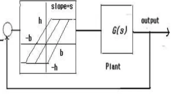
The tuning method of PID controller using saturation function was introduced to improve the accuracy comparing with the use of relay[5]. The method used a pure saturation function is the case with b=0 in Fig. 1.
Fig. 1. A block diagram of autotuning with a saturation function having a memory
The stable limit cycle was observed in plant output with a pure saturation function in Fig. 1. The observed amplitude and period in the plant output
were used to identify the intersection point with the negative real axis, so called crossover point, in the Nyquist plot of linear plant G(s). A describing function method[6] was used to identify the crossover point, which was resulted in the equation (1).
1 +G ( jwc) ⋅Nsa t(a ) = 0 (1)
where is a observed frequency of plant output,
is the observed amplitude of plant output, and .
Nsa t(a) =
{
2πs[
a r c s in( sah )s+ sah 1 -( sah )2]
ifif dd ≤> sasais called a describing function of a saturation function which is as if a equivalent linear gain of saturation function even though the saturation function is a nonlinear element. Note that one point information of was calculated by
. A PID controller was designed using the value of [5]. The calculated value was equals to the value of intersection point with the negative real axis in the Nyquist plot of G(jw).
PID controller was designed with an information of crossover point. However, the use of pure saturation function can be chattered in the presence of noise or a short duration of pulse type disturbance, which results in inaccurate identification of . In this case, it is desired using a saturation function having memory shown in the Fig. 1 insead of pure saturation function in the autotuning. A similar idea was used to remove the chattering in the relay control system. However, we need to modify the autotuning method when we use the saturation function having memory, although a saturation function having memory can be approximated as the pure saturation function if b is small enough. To demonstrate the error resulted from the approximation, consider a linear plant
with b=0.3, h=1, and s=2.
One can verify that the real crossover point of G(s) is equal to As shown in the Fig.
2, the amplitude of plant output , the frequency of plant output, for
pure saturation function case, and , the frequency of plant output, for the saturation function having memory case.
Fig. 2. The outputs of plant(the solid line is for a pure saturation function and the dashed line is for a saturation function having memory)
Using the equation (1), one can verify that the crossover point identified using a pure saturation function, , and the crossover point identified using the saturation function having memory, . The identification error with the saturation function having memory is much larger than that of the pure saturation function. Hence we need to modify the equation (1) when we use a saturation function with memory improving the accuracy of identification of one point in the Nyquist plot of plant G(s).
2.2 The harmonic balance analysis with a saturation function having memory
We use a harmonic valance equation for a plant output y(t) and an output of saturation function with memory to find out the one point information from the amplitude and frequency of the plant output. Suppose that the plant output
⋅ . Then plant output p(q) is defined as in the Fig. 3 where ,
,
,
and
Fig. 3 The output of a saturation function with memory
The plant output y ( t ) can be represented by the following Fourier series. y( t) = ∑∞
k= - ∞ake jkwt , where ak are Fourier series coefficients. We can also represent the output of saturation function with memory, ψ ( - y ) , in Fourier series with the same frequency as ψ( -y) = k∑∞
= - ∞cke jkwt where ck are the Fourier series coefficients. Since y ( t ) is the output of the plant, G ( s) , and ψ ( - y ) is an input of the plant, the following equation should hold
d ( p )y ( t) - n ( p )(ψ ( - y ) ) = 0 (2)
where p = d ( )d t , n(s) and d(s) are the numerator and denominators polynomials of G(s). Using the following relation,
d ( p ) k= - ∞∑∞ ake jkwbct = k= - ∞∑∞ d ( jkw bc)ake jkwbct n ( p ) k∑∞
= - ∞cke jkwbct = k∑∞
= - ∞n ( jkw bc)cke jkwbct the equation (2) can be rewritten as
∑∞
k= - ∞[d ( jkwbc)ak-n ( jkw bc)(ck) ]e jkwbct= 0 (3)
Since e jw bckt are orthogonal for each k, the
equation (3) is equivalent to
G ( jkwbc)(ck) -ak= 0 . Then the first order harmonic balance approximation is given by
G ( 0 ) ( c 0) -a 0= 0 (4) G ( jw bc) c1- a2j = 0
(5) where a 0 is the d.c. value of the plant output,
is the d.c. value of the saturation function with memory, and . The Fourier coefficient of first harmonic for the output of saturation function with memory can be calculated as
c1=wbc/2π ⌠⌡
2 π/wbc
0 ψ( - (a sin w bct))e -jwbctd t (6)
The equation (6) can be rewritten by
c1 = 1/π ⌠⌡
q5
q1 p( q)e -jqd q
= 2/π ( ⌠⌡
q2
q1 -h e -jqdq + ⌠⌡
q3
q2 s( - a ⋅ sin (q) - d ) e -jqd q))
where . The Fourier coefficient can be calculated by
(7)
Using the equation (5),
(8)
Using the equation (8), one can verify that the
is calculated as (-1.05-j0.24) with
and , while the real value of G(j0.98)=-1.0-j0.23. Recall that the G(j0.98)=-1.2+j0, if we treat the saturation function having memory as a pure saturation function. The identification
error using the equation (8) is significantly reduced comparing with the case using the equation (1).
2.3 PID controller design
2.3.1 PID controller design
We show that the one point identification in the Nyquist plot of G(jw) with a saturation function with memory is possible in the previous section. A PID controller design is possible with the one point information using a standard frequency design method[7]. Suppose that the desired phase margin is φm for the closed-loop system and the structure of
PID controller is given by
Gc(s) = k( 1 + sTd+ 1
sTi ) where k , Td, and Ti are proportional gain, differential time, and integral time, respectively. To meet the phase margin requirement, the PID parameters of controller transfer function Gc( ⋅ ) are to be chosen such that the following equation is satisfied
∠Gc(jwbc)+ ∠G ( jwbc) = - π + φm (9) where
∠G ( jw bc) = tan - 1(Im ( G ( jw bc)/R e ( G ( jw bc) ) and it can be calculated by the equation (8). Note that is the frequency of plant output with the saturation function having memory. Using the equation (9).
T d = - α + α2+ 1 2wbc Ti = 4T d
(10)
where ∠ .
Since the loop transfer function with the PID controller has to be unit gain at wbc,
| Gc(jw b c)G ( jw b c) | = 1.
││ (11)
Note that can be found using the equation (8).
2.3.2 Example
Consider the plant transfer function is given by
again as used in the previous section. Suppose that the desired phase margin . We use the saturation function having memory with h=1 , s=2, and b=0.3. The plant output is shown in Fig. 2 with the amplitude
and the frequency . The parameters of PID controller can be found as
1.01, and 4.04 using the equation (10) and (11). One can verify that the phase margin with the PID controller is equal to . If we treat the saturation function having memory as a pure saturation function in the design of PID controller, one can find 1.44, and
using the equation (10) and (11) with
. The phase margin is equal to
. Thus the proposed method is more accurate to the design specification than the approximation method.
Ⅲ. Conclusion
We use a saturation function having memory to tune the PID controllers, which is useful in the presence of noise and/or a short duration of external disturbances. We show that the proposed method can improve the accuracy of one point identification of plant comparing with the approximation of the saturation function having memory as a pure saturation function. We propose a tuning rule for PID controller using the saturation function having memory with an arbitrary memory size. We show that the proposed tuning rule improve accuracy of the design criteria comparing with the approximation method. If there is asymmetric limit cycle in the plant output caused by a static disturbance, we need more research on how to remove the effect of static disturbance and/or the tuning rule. It will be our future work.
References
[1] K. J. Astrom and T. Hagglund, Automatic turning of simple regulators with specifications on phase and amplitude margins, Automatica, 20(5):645-651,1984.
[2] K. J. Astrom, Tuning and Adaptation, 13th IFAC World Congress, San Francisco, USA, 1996.
[3] A. Leva. PID autotuning algorithm based on relay feedback. IEE PROCEEDINGS-D, 140(5):328-338, September 1993.
[4] T. S. Schei. A method for closed loop automatic turning of PID controllers. Automatica, 28(3):587-591, 1992.
[5] S. Oh, PID Autotuning Based on Saturation Function Feedback with a Static Load Disturbance, The Trans. of the KIEE, 510(12):542-548, 2002.
[6] H. K. Khalil. Nonlinear Systems, second edition.
Prentice Hall, New Jersey, 1996.
[7] K. Ogata. Modern Control Engineering, third edition. Prentice Hall, 1997.
BIOGRAPHY Seungrohk Oh (Nember)
1980 : BS degree in Electrical Engineering, Hanyang University.
1990 : MS degree in Electrical Engineering, Polytechnic University(New York).
1994 : PhD degree in Electrical Engineering, Michigan State University.
1982-1996: Korea Electric Power Cooperation 1996- : Professor, Dankook. Univ.