ⓒ J. IEMEK 2014 Feb.: 9(1) 43-52 ISSN : 1975-5066
http://dx.doi.org/10.14372/IEMEK.2014.9.1.43
Stabilization of Target Tracking with 3-axis Motion Compensation for Camera System on Flying Vehicle
Sun Yanjie, Dongwoon Jeon, Doo-Hyun Kim
*Abstract : This paper presents a tracking system using images captured from a camera on a moving platform. A camera on an unmanned flying vehicle generally moves and shakes due to external factors such as wind and the ego-motion of the machine itself. This makes it difficult to track a target properly, and sometimes the target cannot be kept in view of the camera. To deal with this problem, we propose a new system for stable tracking of a target under such conditions. The tracking system includes target tracking and 3-axis camera motion compensation.
At the same time, we consider the simulation of the motion of flying vehicles for efficient and safe testing. With 3-axis motion compensation, our experimental results show that robustness and stability are improved.
Keywords : 3-axis camera, Motion compensation, Moving platform, Target tracking, Flying vehicle.
*Corresponding Author([email protected]) Received: 9 Aug. 2013, Revised: 27 Aug. 2013, 28 Sep. 2013, Accepted: 28 Oct. 2013.
Y. Sun, D. Jeon, D.H. Kim: Konkuk University
※ This paper was written as part of Konkuk University's research support program for its faculty on sabbatical leave in 2013.
I. Introduction
Tracking targets from a moving platform, especially from flying unmanned vehicles, is a challenging problem [1, 2] owing to the camera movements and background changes.
Moreover, the target frequently moves in and out of the valid region of view when the vehicle moves too rapidly for prediction.
Existing research, including a traditional motion detector based on background subtraction [3]
and temporal differencing [4], does not properly address the aforementioned situation.
While such work achieved significant results with fixed cameras and static background scenes [5], the methods employed may not be appropriate when the camera moves rapidly in
a wide range or on a changing background.
Recently, there has been a significant amount of research dedicated to solving these problems. In much of this work, Kalman Filters were used to estimate the motion of the targets. Background compensation was performed by assuming a displacement vector of the background from the previous to the current frame. In this way, a compensation algorithm was devised to control a pan-tilt platform(2-axis camera)which could offset the motion of a moving camera. However, their studies could be better convinced if they had considered the robustness of whole system including mechanical hardware. In this paper, we discuss an alternative approach to achieve a more robust and stabilized tacking solution with 3-axis camera motion compensation.
The proposed method consists of two major
parts: first, we set the target object by
clicking the key points with a mouse from
videos captured by a moving camera. After
determining the target template, we track the
target by applying the Kanade-Lucas-Tomasi
(KLT) feature point tracking method. Next, we
calculate the centroid position and transmit it to the processing unit to track the target, and then maintain the target in the center of the image plane. We then use a sensor to determine the attitudes of the flying vehicle, such as roll, pitch and yaw angles. By using these angles, the 3-axis camera compensates for the ego-motion of the flying vehicle and keeps the platform stabilized. While experiments on an actual unmanned flying vehicle would provide an excellent test of our ideas, the likelihood of such vehicles crashing is high. Thus, to avoid the associated economic losses, a simulation environment is built for the purpose of testing the proposed tracking system.
The rest of this paper is organized as follows: in Section Ⅱ , related research is discussed. Section Ⅲ describes the system architecture and hardware devices. Section Ⅳ describes the camera motion compensation method. The target selecting and tracking algorithm are related in section Ⅴ. Section Ⅵ presents the experimental results and shows the effectiveness of our system. Conclusions and ideas for future work are given in Section
Ⅶ.
Ⅱ. Related Work
This section briefly reviews the following two kinds of research previously performed with videos captured by moving devices. These works use visual feedback to compensate for the pan-tilt camera platform in the control loop.
The first compensation method uses the displacement vector of the background from the previous to the current frame. This method can compensate for background changes due to the camera motion. G. L. Foresti et al.[6]
proposed a robust real-time object tracking system for outdoor image sequences acquired by an active camera. Their method focused on the computation of the displacement vector.
Don Murray et al.[7] described a method for real-time motion detection using an active camera mounted on a pan-tilt platform. Image mapping was used to align images of different viewpoints so that static camera motion detection can be applied.
Secondly, the Kalman filter is applied for motion estimation and prediction. Farabi Bensalah et al.[8] demonstrated that the target motion estimation through Kalman filtering was able to detect and compensate for abrupt changes in the target motion. Additionally, they used the Kalman filter to compensate for pan-tilt platform to offset the movement of the camera. In this way a stabilized background is obtained, despite the fact that the camera is moving. W. Kruger[9] described a compensation algorithm which computes the required image-warping parameters from an estimate of the relative motion between the camera and the ground plane.
The previous research is useful for motion compensation through software. However, little attention has been devoted to the robustness of a whole system, including the mechanical and computing hardware. In addition, image stabilization is needed for the camera in a vehicle. Using visual feedback in the control loop requires careful consideration of all effects like time and speed restrictions for real time control, image processing delays, interfacing the controller used in image processing, smoothing the camera motion, and rejecting disturbances. The purpose of this paper is to continue to improve the robustness and stability in tracking by the holistic and simultaneous usage of both camera motion and visual tracking.
Ⅲ. System Description
The tracking system consists of the following devices:
- AHRS (Attitude and Heading Reference
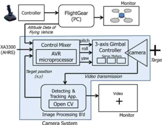
Fig. 1 Block diagram of the camera system
System), e.g. CruizCore XA3300, which provides attitude data, i.e. pitch, roll and yaw angles of moving platform;
- ATmega2560 AVR microprocessor;
- 3-axis platform with three digital servo motors;
- USB camera (640 x 480 at 30 frames per second).
Figure 1 gives the architecture of the whole system. The system consists of a camera on a platform, an AHRS, a 3-axis gimbal, an AVR microprocessor for manipulating the gimbal and an image processing board. The camera can be controlled by commanding the pan and tilt by a DC motor on the 3-axis gimbal. This combination allows the camera to move in the pitch, roll or yaw directions. The servo motors in the gimbal are controlled by an AVR microprocessor, which treats the attitude data from AHRS sensor and receives the target position through UART(Universal Asynchronous Receiver/Transmitter) communication from the image processing board.
The simulator transmits the attitude of the flying vehicle in the simulation provided by FlightGear [10-12] to the AVR microprocessor. FlightGear is a free and open source multi-platform flight simulator [13]. It allows a human being to control the flight in simulation by using a joystick and also
provides attitude data at any moment in the simulation. This data can be sent to an autopilot system.
The video sequences captured from the camera are transmitted to the image processing board which executes the target detection and selection codes using OpenCV [13]. As a result of the target selection, the center position <x, y> of the target is used to calculate the angle of tracking[14]. Then the angles of tracking control are transmitted to the AVR microprocessor. OpenCV is a library of programming functions for real-time computer vision. The development tool used is Microsoft’s Visual Studio 2012.
The AVR microprocessor combines the tracking angles gained from the target position, ego-motion compensation angles gained from the AHRS, and the simulation angle. The combined angles are transmitted to the 3-axis gimbal controller. Consequently, our system can perform simultaneously both compensating for the ego-motion of the flying vehicle and tracking of the target. The simulation system shows that the target is continuously kept at the center of the image plane coordinate.
Ⅳ. Camera Motion Compensation
A flying vehicle usually exhibits substantial shaking during flight. With a camera mounted on such an unstable platform, the target frequently is found to be in and out of the viewing area of the camera. Our goal is to compensate for the motion of the camera by controlling servo motors continuously and, hence, keeping the scene in the viewing area stabilized despite the flying vehicle's violent and abrupt shaking.
Controlling the servo refers controlling the pulse width of the PWM(Pulse Width Modulation) signal [15, 16].
In order to generate a PWM signal, a timer
and interrupt are used to control the width of
the pulse precisely. The timer is managed by a
system clock, and the period of the timer can be set up as desired. We can adjust the period of the timer to trigger the interrupt, and when the timer interrupts Pulse.x times, we can generate the desired pulse width by setting the PWM pin of AVR to ‘1’, which consequently controls the degree of a corresponding motor.
For example, when a 50Hz PWM signal is used to drive the motor and the timer period is set up as 50μs and then, if we set the pin to ‘1’ when the timer works 30 times, then a PWM signal with a pulse width 1.5ms is generated. Since the meaning of the pulse width is usually interpreted by the motor as in formula(1), a pulse of 1.5ms width sets the servo angle to degree zero.
ServoAngle = (Pulse.x - 1500)/10 (1) In formula (1), ServoAngle stands for the rotation angle of the servo motor, in degrees, and Pulse.x stands for the width of PWM pulse, and the unit of Pulse.x is μs.
In our camera compensation system,the pulse width is determined in the Control Mixer block in Figure 1 by combining the three angles; 1) angle for ego-motion compensation, 2) angle from FlightGear simulatior, and 3) angle for real-time tracking.
Thus,formula (2) is,
ServoAngle = Angle.tracking+
Angle.compensation+ Angle.simulator (2) Using formula(2) and (3), we can get the pulse.x :
pulse.x = (Angle.tracking+Angle.compensation +Angle.simulator)*10 + 1500 (3) Angle.tracking is the angle of the contribution calculated by the image tracking application. This angle reflects the offset of the target image from the center of the viewing area. Angle.compensation compensates for the ego-motion. This angle reflects the roll, pitch, and yaw components obtained from
the AHRS. Angle.simulator reflects the current attitude of the virtual flying vehicle simulated by FlightGear.
Ⅴ. Target Selecting and Tracking
In order to select and track a target as we desired, we use the well-known KLT feature point tracker. Other detecting techniques such as color histogram [17] can still work in the moving camera scenario. However, they are too sensitive to lighting variation; traditional detectors may fail when the camera moves or the background changes. Since this paper focuses on motion compensation and stabilization, and robustness against environment change, a more complex algorithm is not necessary[18]. We use the KLT algorithm proposed by Lucas and Kanade.
The steps are as follows:
a) Detect the feature points of the current frame;
b) Add or remove the feature points by clicking the mouse;
c) Determine the target through feature point selection;
d) Describe the target with the feature points labeled by green color, and with the center labeled by red color;
e) Discard the useless feature points and use the remaining feature points as a template, then calculate the center position<x, y> on the image plane coordinate;
f)Use optical flow to track these feature points between the frames;
g)Describe the trajectory of the target's center with a yellow line.
Ⅵ. Experiments
The experiments were performed on a
scene (640 x 480 at 30Hz) from a Microsoft
Life Cam video camera device. The computer
Fig. 2 Target selecting
Fig. 3 Target tracking
processor for image processing used was an Intel Core i5-2500, 3.60 GHz.
1. Target selecting and tracking
We utilized a human hand as a moving target to track. We selected the feature points in the domain of the hand as shown in Figure 2 by applying steps b) to d) as given above.
When the hand moved freely, the feature points also moved with the mobile target. The yellow line is the trajectory of the target's center as in Figure 3. In such a complex background environment, it is difficult to avoid a slight change of the position of the feature points. However, after processing with the algorithm, we obtained a correct location of the target.
2. Camera real-time tracking
In order to experiment with the effectiveness of the camera tracking system, we installed the same camera system on the
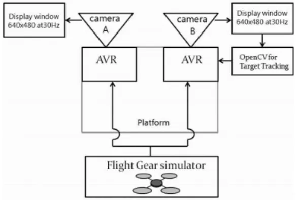
Fig. 4 Tracking experiment configuration
Fig. 5 Experimental result of target with random movement (camera A)
same platform as illustrated in Figure 4. We held the platform manually to move freely to simulate the global motions of the flying vehicle. In addition, the attitude data of the simulated flight were fed into a two camera system; cameras A and B. Thus, the platform can be seen as a simulation of a flying vehicle which has global motion and ego-motion. We ignored small differences between the initial positions of the two cameras and assumed these two camera systems were under the same conditions. The one difference between the cameras is that the OpenCV image tracking was not applied to camera A.
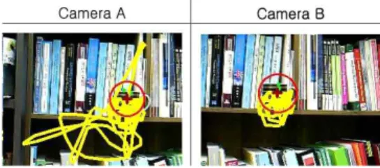
In Figure 5 and Figure 6, we set a fixed
cup as the target. We can see that the
variance of the position in camera A is much
larger than that of camera B because the
tracking was not applied to it. We find the
same results in the trajectories of each one.
Fig. 6 Experimental result of target with tracking (camera B)
Fig. 7 Experiment configuration for compensation with AHRS
The trajectory of camera B was relatively stable in spite of its swings. Although it moved away from the center block occasionally, it returned automatically. This indicates that means our method tracks the target properly.
3. Camera compensation
We added a tracking block to the system for camera A. Meanwhile, we added the motion compensation block to the system for camera B as shown in Figure 7. Figure 8 and Figure 9 show, respectively, the movements of camera A with only tracking; and the trajectory of camera B with both tracking and compensation.
The coordinates <A.x, A.y>, <B.x, B.y> are, respectively, the target positions on the image planes of camera A and camera B. The roll, pitch, and yaw are the attitudes of each camera system in swings. We tested our
Fig. 8 Result of Camera A with tracking only
Fig. 9 Result of Camera B with tracking and compensation with AHRS
systems for 30s. During first 10s, we tested the roll direction while its pitch and yaw were almost maintained. In the next 10s we tested the pitch in the same way, and in the final 10s, we tested the yaw.
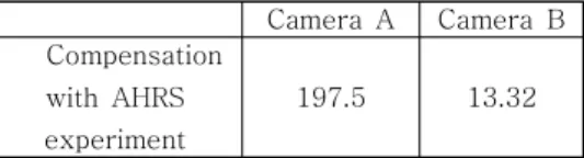
To confirm the effect of our method, we calculated the MSE(mean square error) according to formula (4). The ideal tracking position was (320, 240) which was the coordinate of the center. As a result, we got the MSE for camera A as 197.5, and for camera B as 13.32.
As shown in Table 1, the MSE of A was
197.75 and that of B was 13.32. Although
camera A may track the target, when the
angles' rate of the pitch, roll, and yaw change
rapidly, the position of the target captured by
Camera A Camera B Compensation
with AHRS experiment
197.5 13.32
Table 1. MSE comparisons of ego-motion
camera A sharply changed accordingly. Owing to the large ego-motion, the target moved out of the viewing area. The tracker failed to locate the target when the angular velocity was more than 62 degree/s. In this case, the position of the coordinate <A.x, A.y> was reset to <0, 0>. On the other hand, in the test with camera B with 3-axis camera compensation and attitude data from the flying vehicle in simulation, a stabilized tracking was obtained, despite the constant motion of the camera.
4. Additional factors on compensation
We considered the effects of the vehicle speed, the distance between the target and the camera, and the vehicle acceleration in the compensation experiments. We do not list all of the data obtained, but we analyzed the experimental results by using all of them. We have listed the average, minimum and maximum value, and we have also given the target's trajectory.
In this section, we repeated each of the experiments several times. We selected typical and representative data to analyze the results.
We measured 600 frames within 20s, and plotted every 10 frames, as we have done our study of the ego-motion. We made the angles of ego-motion randomly change in a small range to simulate a vehicle flying under normal conditions. The directions of global motion were also randomly varied. As camera A and camera B both tried to maintain the position of the coordinates of the center, the motion direction was not important.
Firstly, we tested the effects of the distance between target and camera. We kept
Fig. 10 Result of trajectory when distance between target and camera changes
Camera A Camera B
Figure 10 40.19 8.02
Figure 11 81.35 22.46
Figure 12 93.56 25.38
Figure 13 102.14 32.08
Figure 14 257.98 36.29
Table 2. MSE comparisons from changes of distance, speed and acceleration
the other conditions same, and changed the distance in the range 0.5 – 2m. The trajectory diagram is shown in Figure 10 and the calculated MSE is given in Table 2:
Secondly, We tested the effects of the vehicle speed. An average speed was 0.21m/s, the maximum speed was 0.27m/s, and the minimum was 0.17m/s. Next, we sped up to an average of 0.48 m/s. The maximum value in this test was 0.58m/s, and the minimum was 0.45m/s. The results of this experiment are shown in Figure 11 and Figure 12.
Lastly, the effects of the vehicle acceleration were tested. We tested two values of the acceleration. One is an average acceleration of 0.02G; the maximum value was 0.07G, and the minimum was 0.01G. The other, we used an average acceleration value of 0.08G; the maximum value was 0.19G, and the minimum was 0.01G. The results are shown in Figure 13 and Figure 14.
From the above experimental data, we can
see that there is a little effect on the results
from varying the distance between the target
and the camera. In Figure 10, the MSE can be
accounted for almost entirely by the random
Fig. 11 Result of trajectory when vehicle speed is 0.21m/s
Fig. 12 Result of trajectory when vehicle speed is 0.48m/s
ego-motion.
Through the analysis of Figure 11 and Figure 12, we draw the conclusion that the vehicle speed does not affect the compensation effect significantly.
As shown in Figure 13 and Figure 14, the vehicle acceleration clearly influences the tracking system greatly. When the acceleration is large, the tracking camera without the compensation method could not track accurately; the target moved out of the viewing area.
We compare our results with the existing research results of Farabi Bensalah et al.[10], which used the Kalman filter to compensate for a pan-tilt platform to offset the movement of the camera. Their maximum value of tracking error was 30 pixels and mean value was 5 pixels. G. L. Foresti and C. Micheloni[6]
estimated the displacement vector due to the camera motion and then applied it to locate the mobile camera. Their mean value of error was 2.21 pixels, and their maximum value is 14.35 pixels.
In this paper, we calculated five cases of the MSE; calculating the tracking error using
Fig. 13 Result of trajectory when vehicle acceleration was 0.02G
Fig. 14 Result of trajectory when vehicle acceleration was 0.08G
the original data, our mean value was 1.19pixels, and our maximum value is 8.27 pixels.
These experimental results indicated that our proposed method performs meaningful stabilization with real-time tracking for a camera system with ego-motions on a flying vehicle.
Ⅶ.Conclusions
In this paper, we proposed an integrated
method for the stabilization of a moving
camera system with target tracking and motion
compensation. The method allows us to
maintain the platform to be stabilized. As
shown in Table 1, under the same tracking
conditions, when we use camera motion
compensation, the MSE was lowered to 13.32,
showing that the negative effects due to
camera motion can be eliminated. Compared
with other tracking systems with compensation,
our method gives better results, tracks the
target in a relatively wide range and improves
the robustness and stabilization of the whole
tracking system. In addition, considering the difficulties of experimenting on flying vehicles, we proposed a simulation model to improve the efficiency and safety of studying flying vehicles.
Despite our success, we encountered a limitation with the image processing method that we used. When the target moved out of the viewing area, the feature points disappeared. In future work, we will improve this algorithm by using richer information from the flying vehicle, such as the roll, pitch, and yaw’s rate or/and acceleration to evaluate and predict the motion magnitude. Through such proposed research, we expect to compensate for both the ego-motion and global-motion of the flying vehicle more accurately.
References
[1] M. Betke, E. Haritaoglu L.S. Davis,
"Real-time multiple vehicle detection and tracking from a moving vehicle," Machine Vision and Applications, Vol. 12, No. 2, pp.69-83, 2000.
[2] H. Tao, H. Sawhney, R. Kumar, "Object t racking with bayesian estimation of dynamic layer representations," IEEE Transactions on Pattern Analysis and Machine Intelligence, Vol. 24, No. 1, pp.75-89, 2002.
[3] Z. Kim, "Real time object tracking based on dynamic feature grouping with background subtraction," Proceedings of the IEEE Conference on Computer Vision and Pattern Recognition, pp.1-8, 2008.
[4] Y.J. Zhong, S.P. Zhang, "Robust object tracking using camshift with multicue integration," Proceedings of the International Conference on Machine Vision, Vol. 8349, 2011.
[5] L. Li, W. Huang, I. Gu, Q. Tian, "Foreground object detection from videos containing complex background," Proceedings of the ACM international conference on Multimedia, pp.2-10, 2003.
[6] G.L. Foresti,C. Micheloni, "A robust feature tracker for active surveillance of outdoor scenes," Electronic Letters on Computer Vision and Image Analysis, Vol. 1, No. 1, pp.
21-34, 2003.
[7] D. Murray, A. Basu, "Motion tracking with an active camera," IEEE Transactions, Vol. 16, No. 5, pp.449-459, 1994.
[8] F. Bensalah, F. Chaumette, "Compensation of abrupt motion changes in target tracking by visual servoing," Proceedings of the IEEE International Conference on Intelligent Robots and Systems, Vol. 1, pp.181-187, 1995.
[9] W. Kruger, "Robust real-time ground plane motion compensation from a moving vehicle,"
Machine Vision and Applications, Vol. 11, No.
4, pp.203-212, 2005.
[10] E.F. Sorton, S. Hammaker, "Simulated flight testing of an autonomous unmanned aerial vehicle using FlightGear,"
Infotech@Aerospace(AIAA), 2005.
[11] H. Huang, Y.P. Xu, Z.W. Deng, "Real-time visual flight simulation system based on flightgear simulator," Journal of System simulation, Vol. 19, No. 19, pp.4421-4423, 2007.
[12] J. Craighead, R. Murphy, J. Burke, B.
Goldiez, "A survey of commercial & open source unmanned vehicle simulators,"
Proceedingd on IEEE International Conference of Robotics and Automation, pp. 10-14, 2007.
[13] http://opencv.org
[14] S.J. Park, S.W. Ha, "Bomb impact point location acquisition by image transformation using high-resolution commercial camera,"
Journal of IEMEK, Vol. 6, No. 1, 2011 (in Korean).
[15] J.O.P. Pinto, L.E.B. Silva, "A Neural-Network-Based Space-Vector PWM controller for voltage-fed inverter induction motor drive," IEEE Transactions on Industry Applications, Vol. 36, No. 6, pp.660-669, 2000.
[16] M.P. Kazmierkowski, A.B. Kasprowic,
"Improved direct torque and flux vector
control of PWM inverter-fed induction
motor drives," IEEE Transactions on Industrial Electronics, Vol. 42, No. 4, pp.344-350, 1995.
[17] W. Lu, Y.P. Tan, "A color histogram based people tracking system," IEEE Circuits and Systems, Vol. 2, pp.137-140, 2001.
[18] S.T. Kwon, S.H. Park, M.G. Joo, "An indoor user-tracking mobile robot based on infrared signal detection," Journal of IEMEK, Vol. 7, No. 1, 2012 (in Korean).
A u t h o r s
Sun Yanjie
2012: B.E. degree in electronics engineering from Konkuk University, Korea.
Current: M.S. candidate in the school of Computer, Information &
Communications Engineering at Konkuk University, Korea.
Research Interests: embedded software, computer vision.
Email: [email protected]
Dongwoon Jeon
2005: B.E. degree in internet & multimedia
engineering from
Konkuk University, Korea.
2008: M.S. degree in internet & multimedia engineering from Konkuk University, Korea.
Current: Ph.D. candidate in the school of Computer, Information & Communications Engineering at Konkuk University, Korea.
Research Interests: embedded software, computer vision, UAV.
Email: [email protected]
Doo-Hyun Kim
1985: B.E. degree in Computer Science from
Seoul National
University, Korea.
1987: M.S. degree in Computer Science from KAIST.
2003: Ph.D. degree in Computer Science from KAIST.
Current: Professor, Department of Internet & Multimedia Engineering Konkuk University.
Research Interests: embedded software, Real-time OS.
Email: [email protected]