Article Information
Manuscript Received July 6, 2020, Revised October 5, 2020, Accepted October 20, 2020, Published online December 30, 2020 The authors are with Department of Computer Electronics, SEOIL University 28, Yongmasan-ro 90-gil. Seoul 02192, Republic of Korea.
Correspondence Author: Seon Hack Hong ([email protected])
ORCID: 0000-0001-9524-7863 (S. H. Hong); 0000-0001-7656-4986 (S. J. Lee); 0000-0002-6774-5731 (H. J. Park)
This paper is an open access article licensed under a Creative Commons Attribution-NonCommercial-NoDerivatives 4.0 International Public License.
To view a copy of this license, visit http://creativecommons.org/licenses/by-nc-nd/4.0
Seon Hack Hong, Seong June Lee, Hyo Jun Park
Abstract
In this paper, we designed the COS MEMS system for sensing the falling detection and explosive noise of fuse link in COS (Cut Out Switch) installing on the power distribution. This system analyzed the failure characteristics and an instantaneous breakdown of power distribution.
Therefore, our system strengths the industrial competence and guaranties the stable power supply. In this paper, we applied BLE (Bluetooth Low Energy) technology which is suitable protocol for low data rate, low power consumption and low-cost sensor applications. We experimented with LSM6DSOX which is system-in-module featuring 3 axis digital accelerometer and gyroscope boosting in high-performance mode and enabling always-on low-power features for an optimal motion for the COS fuse holder. Also, we used the MP34DT05-A for gathering an ultra-compact, low power, omnidirectional, digital MEMS microphone built with a capacitive sensing element and an IC interface. The proposed COS MEMS system is developed based on nRF52 SoC (System on Chip), and contained a 3-axis digital accelerometer, a digital microphone, and a SD card. In this paper of experiment steps, we analyzed the performance of COS MEMS system with gathering the accelerometer raw data and the PDM (Pulse Data Modulation) data of MEMS microphone for broadcasting the failure of COS status.
Keywords: COS, Cut Out Switch, BLE, Bluetooth Low Energy, COS MEMS System, LSM6DSOX, MP34DT05-A
I. Introduction
It is essential for high quality of power distribution to compete with the advanced information society of occupying the stable performance in our lives and the industries. The instantaneous breakdown of power distribution supply could cause the efficiency drop of industry fields and therefore we need to sustain the stable power distribution with developing the technology of distribution power system [1]. The power distribution system is connected with various equipment such as COS, power transformers, and many switches. The power system is exposed to many interruption possibilities, the most important of which are those due to primary overhead, underground cable failure or transformer failure. The distribution feeders had been available for COS to restrict the interruption caused by failures of overhead transformer and secondary loads.
COS has the typical explosive fusing characteristics, the most basic and efficient type of fault current interrupting. And it is also one of the most reliable devices that can provide its function for over 30 years with no maintenance. Fig. 1 shows the COS that is consisted with polymer body, upper/lower connectors and fuse holder. The fuse holder has fuse link that includes fusible element to activate via the fault current [2][3].
When the fault current flows, the fusible element is melt making an arc in the fuse link. The produced arc will rapidly create
gases from vulcanized fiber located in close to the fusible element.
The gases generated by the fiber are to be deionized and allow a rapid buildup of dielectric strength that can withstand the transient recovery voltage and steady state power system voltage. The polymer body should sustain the fuse link with enough mechanical Fig. 1. Structure of COS and COS MEMS System.
strength during stable status of power distribution system [4][5].
In this paper, we experimented an accurate detection technology of COS failure with sensing the vibration of fusible element or opening of COS via LSM6DSOX accelerometer, gathering the sound of explosive noise by MP34DT05 for MEMS audio sensor omnidirectional digital microphone built with a capacitive sensing element, and saving the temporary data before broadcasting over BLE to SD card [6][7].
II. Hardware Design
A. MEMS Accelerometer and Gyroscope
In this paper, we used LSM6DSOX which is a system-in-package featuring a high-performance 3-axis digital accelerometer and 3- axis digital gyroscope and delivers best-in-class motion sensing that can detect orientation and gestures in order to empower application developers with features and capabilities that are more sophisticated than simply orienting its devices to portrait and landscape mode as shown in Fig. 2.
The event-detection interrupts enable efficient and reliable motion tracking and contextual awareness, implementing hardware recognition of free-fall events, stationary or motion detection of power distribution system.
B. MEMS Microphone
The digital MEMS microphone is a sensor that convert acoustic pressure waves into a digital signal. The MPU acquires digital data from the microphone through particular peripherals to be processed and transformed into data standard for audio. The audio data is then handled by the microcontroller according to the targeted audio application as shown in Fig. 3.
The main parts in a digital microphone are a MEMS transducer, an amplifier and a PDM modulator. PDM modulator converts the
buffered analog signal into a serial pulse density modulated signal.
The clock input (CLK) is used to control the PDM modulator. The clock frequency range for digital microphones is from 1 MHz to 3.25 MHz. This frequency defines the sampling rate at which the amplifier’s analog output signal is sampled to produce a discrete time representation. PDM is a form of modulation used to represent an analog signal in the digital domain. It is a high frequency stream of 1-bit digital samples. In a PDM signal, the relative density of the pulses corresponds to the analog signal's amplitude.
C. SD Card with SPI
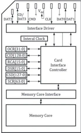
A block diagram of the SD card is shown in Fig. 4. The SD card consisted of a 9-pin interface, a card controller, a memory interface and a memory core. The 9-pin interface allowed the exchange of data between a MEMS embedded system and the card controller as shown in Fig. 3. The controller could read/write data from/to the memory core using the memory core interface. In addition, several internal registers stored the state of the card.
The controller responded to two types of user requests:
control and data. Control requests set up the operation of the controller and allowed access to the SD card registers. Data requests were used to either read data from or write data to the memory core.
Communication with the SD card is performed by sending commands to it and receiving responses from it. A valid SD card command consists of 48 bits as shown in Fig. 5. The leftmost two bits are the start bits which we set to (01). They are followed by a 6-bit command number and a 32-bit argument where additional Fig. 3. Sound acquisition system.
Fig. 4. Block diagram of SD card.
Fig. 5. A valid command format of SD Card
information may be provided. Next, there are 7 bits containing a Cyclic Redundancy Check (CRC) code, followed by a single stop bit (1).
Microcontrollers are relatively memory constrained, e.g., 512 Kbytes flash, which limits the ability to store large quantities of data either as inputs to or outputs from an embedded program. SD cards provide a cost-effective solution which can be accessed by both the processor and user. In practice, these cards have file systems (typically FAT) and can be inserted in commonly available adaptors.
Communicating with an SD memory card is relatively simple using some SPI driver like the one described in the previous section.
However, controlling the card and interpreting the data communicated requires significant additional software. Such software practically elevates the level of access to the card to a higher level of abstraction as illustrated in Fig. 6.
D. MCU Features
The main microcontroller with COS MEMS system is ARM Cortex-M4 processor with floating-point unit (FPU) has a 32-bit instruction set that implements a superset of 16 and 32-bit instructions to maximize code density and performance. This processor implements several features that enable energy-efficient arithmetic and high-performance signal processing. The ARM Cortex Microcontroller Software Interface Standard (CMSIS) hardware abstraction layer for the ARM Cortex processor series is implemented and available for the M4 CPU [8].
We experimented the COS MEMS system with MEMS accelerometer and microphone for detecting the status of COS.
Therefore, we designed the embedded platform for sensing the fault
of COS as shown in Fig. 7.
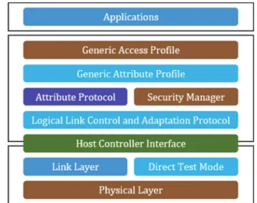
E. Architecture of BLE
In this paper, we used the BLE technology for transferring the COS fault data to Decentralized Control Unit. Fig. 8 shows the different layers within the architecture of BLE. The three main blocks in the architecture of a BLE device are: the application, the host, and the controller [9]-[11]. The application layer is use-case dependent and refers to the implementation on top of the Generic Access Profile and Generic Attribute Profile - it is how your application handles data received from and sent to other devices and the logic behind it.
F. Layers of BLE
The physical layer (PHY) refers to the radio hardware used for communication and for modulating/de-modulating the data. BLE operates in the ISM band (2.4 GHz spectrum), which is segmented into 40 RF channels, each separated by 2 MHz (center-to-center), as shown in the following Fig. 9.
Three of these channels are called the primary advertising channels, while the remaining 37 channels are used for secondary advertisements and for data transfer during a connection.
Advertising always starts with advertisement packets being sent on the three primary advertising channels (or a subset of these channels). This allows the devices scanning for advertisers to find them and read their advertisement data. The scanner can then Fig. 6. SD Card software stack.
Fig. 7. Hardware structure of COS MEMS system.
Fig. 8. Architecture of BLE.
Fig. 9. Frequency spectrum and RF channels in BLE.
initiate a connection if the advertiser allows it. It can also request what’s called a scan request, and if the advertiser supports this scan request functionality, it will respond with a scan response. Scan requests and scan responses allow the advertiser to send additional advertisement data to devices that are interested in receiving these data [12].
III. Software Driver Design
COS MEMS system has four components of peripheral devices which are LSM6DSOX, MP34DT05-A, SD card and BLE. These components are performed as organic collaboration.
A. COS MEMS System Structure
In some case of any events from sensors would not happen, the accelerometer and microphone’s data would not store to SD card. When the events happened, gathering the data of the time before and after of events, and storing them to the SD card. By storing the data on SD card, we could monitor the motion at the time of events with its data analyzing via excel. We designed the special queue structure to store the data of the time before and after events occurred. The queue saved the upcoming data from motion driver, therefore we used push function for collecting motion data. After the events done, the pop function worked for the motion data taking out from the queue.
Software driver structure as shown in Fig. 10 represented the relationship between hardware and software which are consisted with motion, audio, and datalog function. SensorQ, which is called special queue included in user application temporarily stored the data of motion driver, however audio and datalog driver directly connected to the user application [13][14]. When the events finished, the SD card stored data of queue and audio buffer. The data stored as CSV and WAV file formats, which could analyze on the
personal computer. By storing data to these formats, we could easily access and process the data in order to detect the fault status.
Fig. 11 represented the driver architecture of COS MEMS system. Motion is the API which defined interactions between LSM6DSOX driver and User Application. It worked as an initializer and data handler which is communicated with LSM6DSOX driver.
LSM6DSOX had two communication protocols which are I2C and SPI which used in this paper. Physically the software and hardware are connected by SPI protocol for the purpose of speeding up.
In the case of I2C communication protocol speed up to 400 KHz, but SPI protocol speed up to 10 MHz and therefore we used 4 MHz frequency of SPI. LSM6DSOX driver is the API which defined interactions between SPI driver and User Application. This driver is used for setting the registers of LSM6DSOX which are accelerometer and gyroscope.
Audio is the API which is defined interactions between PDM driver and user application. It worked as an initializer and data processer which is managed for PDM driver. Audio sampling frequency is 16 kHz that gave us accurate signal of events.
MP34DT05-A is an ultra-compact, low-power, omnidirectional, digital MEMS microphone built with a capacitive sensing element and an IC interface. The sensing element, capable of detecting acoustic waves, is manufactured using a specialized silicon micromachining process dedicated to producing audio sensors. The IC interface is manufactured using a CMOS process that allows designing a dedicated circuit able to provide a digital signal externally in PDM format. When the PDM driver received the audio data from MP34DT05-A, it triggered the PDM interrupt to process the audio data. The audio data is processed by AudioProcess function which stored the data to buffer.
The datalog which interfaced between FAT & SD driver and User Application saved data to the SD card. Datalog created files such as CSV and WAV file for logging the data of motion and audio when the events happened. Sending a command to the SD card is performed in serial fashion. By default, the MOSI line is set to 1 to indicate that no message is being sent. Once the SD card received a command, it would begin processing it. To respond to a command, Fig. 11. Driver architecture of COS MEMS system. Fig. 13. Format of the 40-bit response.
the SD card required the SD CLK signal to toggle for at least 8 cycles.
The length of a response message varied depending on the command. Most of the commands got a response mostly in the form of 8-bit messages, with two exceptions where the response consists of 40 bits [15].
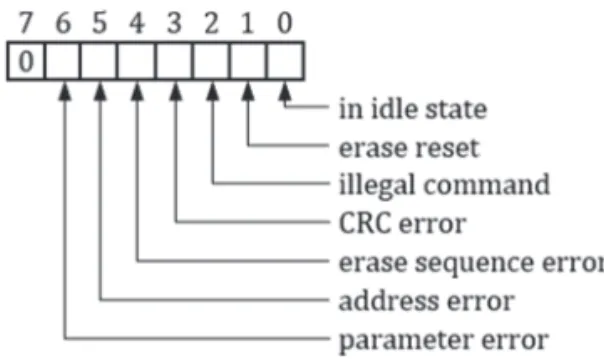
To ensure the proper operation of the SD card, the SD CLK signal should have a frequency in the range of 100 to 400 kHz. To communicate with the SD card, it should be into the SPI mode. To do this, set the MOSI and CS lines to logic value 1 and toggle SD CLK for at least 74 cycles. After the 74 cycles or more, the CMD0 sent to the SD card. CMD0: This is the reset command, which puts the SD card into the SPI mode. The SD card would respond to the reset command by sending a basic 8-bit response. The structure of this response is shown in Fig. 12.
Following a successful reset, COS MEMS system could successfully communicate with the SD card by sending two different commands.
(i) CMD8: This command is only available in the latest cards, compatible with SD card Specifications version 2.0. For most older cards this command should fail and cause the SD card to respond with a message that this command is illegal.
(ii) CMD58: This command requests the contents of the operating conditions register for the connected card.
A response to these commands consisted of 40 bits, where the first 8 bits are identical to the basic 8-bit response, while the remaining 32 bits contain specific information about the SD card. If successful, the first 8 bits of the response would be either 00000001or 00000101 depending on the version of your SD card.
The complexity of SD card communication protocol needed the SD card driver to connect SD card. FAT file system of SD card required to interface with personal computer for exchanging the amount of data.
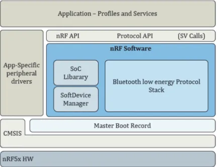
B. BLE Software Architecture
We used the SoftDevice as depicted in Fig. 14. A SoftDevice is a wireless protocol stack library for building System on Chipsolutions. SoftDevices are precompiled into a binary image and
functionally verified according to the wireless protocol specification, so that all you have to think about is creating the application.
The unique hardware and software framework provide runtime memory protection, thread safety, and deterministic real- time behavior. The Application Programming Interface (API) is declared in header files for the C programming language. These characteristics make the interface similar to a hardware driver abstraction where device services are provided to the application, in this case, a complete wireless protocol [16]-[18].
C. COS MEMS System’s Software Flow
The software flow of COS MEMS system is shown in Fig. 15.
IV. Experiments
A. Hardware Result
The MEMS Embedded platform has 4 modules which are MCU, Accelerometer, Microphone, and SD card as a system-in-module as shown in Fig. 16. The MEMS platform allowed to sense the status data.
Fig. 15. Software flow of COS MEMS system.
Fig. 16. PCB artwork of COS MEMS system.
Fig. 14. SoftDevice architecture of nRF5x.
We used the MCU as the main unit to control the acceleration sensor with SPI protocol and sound sensor with PDM, and transmit sensor data to SD card for storing the temporary motion status data.
The PDM module enabled input of pulse density modulated signals from external audio frontends, digital microphones. The PDM module generated the clock and supports single-channel or dual- channel (Left and Right) data input.
B. COS Fuse Link Test Environments
In our laboratory, we have installed the testbed of COS MEMS system for experimenting the various COS fuse holder failure tests like Fig 17. We used fuse link for test of laboratory experiments on 1-25 A specifications at Joong Won electric company with insulator and polymer type COS.
C. Audio and Accelerometer Waveform at Fuse Link Failure We experimented the fuse holder failure tests with recording the audio waveform and 3 axis accelerometer sensor data like Fig.
18. At these experiments, we used the range from 1 A to 25 A fuse link made by Joong Won electricity company. The Fig. 18 showed that the test results of 10 A fuse link. The audio waveform frequency ranges are from 0 to 47799 Hz and the FFT analysis is based on the Blackman-Harris Window. The 3 axis accelerometer sensor data had x, y, z-axis features [19]-[21].
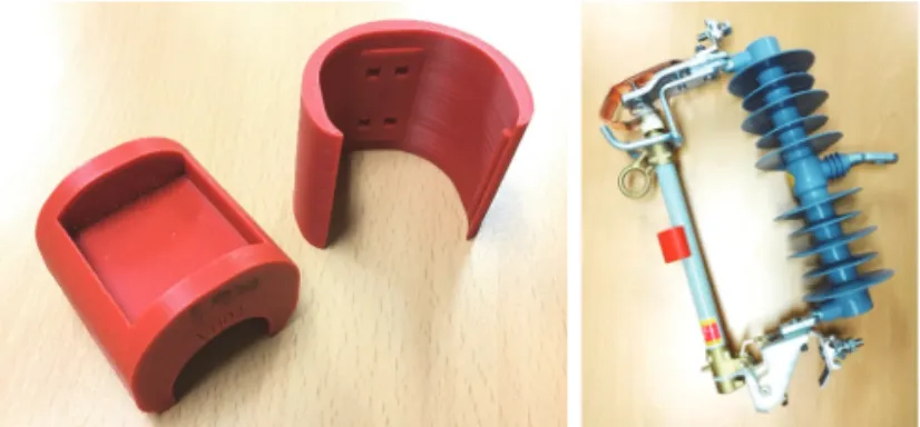
D. COS MEMS System Housing
We designed the COS MEMS System housing with 3D modeling and installed like Fig. 19. COS MEMS System housing was designed for focusing easily adhere to COS fuse holder, avoiding the environmental factors such as dust, water proof, and climate and holding the induced coils for charging the power consumption of COS MEMS system.
V. Conclusion
In this paper, we implemented the Embedded platform for detecting the COS failure with bluetooth low energy wireless communication in the power distribution system. Failure analysis of COS caused electricity outage in distribution system and the majority causes are burned down of fuse links and fractured porcelain body. Especially we experimentally designed the COS MEMS system. At this point we acknowledged a certain level of hardware and software embedded architecture design and BLE communication technology. Afterwards, we would enhance the performance of wireless embedded platform with adapting the flexible MEMS technologies of predicting the COS status in these fields.
Fig. 18. Waveform of Audio, FFT analysis and Accelerometer data.
[1] Seon Hack Hong, “Embedded system Design with COS LoRa technology,” Korea Society of Digital Industry and Information Management, 3rd 14, pp.29-38, 2018.
[2] Jong Man Joung, Dong Myeong Kim & Myung Ho Choi, “Failure Analysis of COS used in Distribution System,” Journal of International Council on Electrical Engineering, JICEE .2011.010.3 pp264-268, 2011.
[3] Pan Seop Sim, “The study of distribution apparatus power transformer COS,” Ph.D. dissertation, Univ. of Hoseo, Korea, 2003.
[4] Hong Yeong Lee, “The study of 22.9kV distribution COS quality improvement,” Univ. of DaeJeon Industry, Korea, 05.2000.
[5] Yu Seop Hwang, “The study of hybrid COS with a built-in acoustic absorber system,” Univ. of ChungJu, Korea, 12, 2011.
[6] STMicroelectronics, LSM6DSOX Datasheet, Geneva Switzerland, 01.2019.
[7] STMicroelectronics, MP34DT05-A Datasheet, Geneva Switzerland, 01.2019.
[8] Nordic semiconductor, nRF52840 Product Specification, v1.1, Trondheim Norway, 02. 2019.
[9] Li Na Lee, Ga Ram Lee & Ho Won Kim, “Wireless technology analysis,”
[13 Arm Limited, Arm Compiler User Guide, Version 6.14, Cambridge UK, 02. 2020.
[14] Arm Limited, Arm Compiler Reference Guide, Version 6.14, Cambridge UK, 02. 2020.
[15] Ata Elahi, Trevor Arjeski, “ARM Assembly Language with Hardware Experiments,” Berlin Germany, 2015.
[16] Seon Hack Hong, “Mobile Arduino Embedded Platform Design,” Korea Society of Digital Industry and Information Management, 4th, pp.33- 41, 12. 2013.
[17] Seon Hack Hong, “Real Time Linux System Design,” Korea Society of Digital Industry and Information Management, 10th, pp.13-20, 06.
2014.
[18] Seon Hack Hong & Kyung Soon Cho, “3D Scanning Embedded System Design,” Korea Society of Digital Industry and Information
Management, pp.49-56, 13th, 12. 2017.
[19] STEVAL-MKI109V3 User Manual, 4, 2019. Available at www.st.com [20] Sei Hyun Lee, Doo Kee Park, Kyung Wan Koo & Sang Ok Han, Dept. of
Electrical Eng., Chun Nam National University. “Analysis of Electrical Field Distribution in an Insulator of COS using FEM,” 12, 1996.
[21] STEVAL-MKI109V3 Professional MEMS Tool motherboard for MEMS adapter, 10. 2018.