<특집호-국방M&S> pISSN 1226-0606 eISSN 2288-6036
지상 전투차량의 명중률 영향요소 분석을 위한 포의 동역학 해석
송재복
1
· 박강2†
1
명지대학교 기계공학과 석사과정,2
명지대학교 기계공학과Dynamic Analysis of the Turret for Analyzing the Accuracy Impact Factor of the Ground Combat Vehicle
Jaebok Song
1
and Kang Park2†
1
Graduate School of Mechanical Engineering, Myongji University2
Department of Mechanical Engineering, Myongji UniversityReceived 18 September 2014; received in revised 13 November 2014; accepted 13 November 2014
ABSTRACT
There are many factors that contribute to hit probability of the gun shot of ground combat vehi- cles. Aiming accuracy is mainly affected by the dynamic state of the vehicle. The stabilization error of the turret under system vibration is one of the major factors that affect the aiming accu- racy. The vibration of the vehicle is affected by both the state of the road and the speed of the vehicle. This paper analyzes the aiming accuracy of the gun equipped on the GCV when the vehicle drives on the different roads and at different speed. The vertical displacement and the pitch angle of the gun are calculated and the impact points of the target are calculated. Distribu- tion of the impact points on the target is greatly influenced by the pitch rotation rather than ver- tical displacement. And this aiming errors result in the errors of point of impacts on the target after the bullet flies through the air under trajectory equations. The GCV is modeled using a half-car model with 6 D.O.F. and the specifications of the M2 machine gun are used in trajec- tory calculation simulation and the target is located in 1000 m away from the gun.
Key Words: External ballistics, Half-car 2D model, Matlab/Simulink, Modeling and simulation, Vehicle dynamics
1. 서 론
본 연구는 지상 전투차량(GCV)의 설계에 있어 서 성능분석을 위한 기초 연구로 차량의 화력성능 에 대한 분석으로 무기의 명중률은 중요한 설계요 소 중 하나다. 그 중 차량의 직사화기의 경우 무기
의 미세한 움직임에도 명중률은 크게 영향을 받는 다고 볼 수 있다. 차량은 노면을 이동할 때 노면의 요철에 따라 차량에 진동이 발생하게 되는데 그 진동에 의해 무기의 수직방향 오차와 피치회전 오 차가 발생한다. 본 논문은 이들 오차가 최종 명중 률에 어떤 영향을 미치는지를 분석한다. 그 과정 은 크게 세 가지로 볼 수 있다. 첫째는 노면에 따 라 포의 수직변위와 피치회전을 계산하기 위해 차 량의 동역학적인 해석을 한다. 본 논문에서는 차
†Corresponding Author, [email protected]
©2014 Society of CAD/CAM Engineers
량의 반차 모델(Half car model)의 운동방정식을 이용한다
[4]
. Matlab/Simulink을 이용하여 운동방정 식을 풀기 위해 운동방정식을 상태방정식(State- space equation)으로 변환하여 그 식을 Matlab/Simulink의 블록(Block)을 이용하여 포의 수직변 위와 피치회전을 계산한다. 둘째로 명중률 분석을 위해 포의 발사각과 총신에서 초기속도를 가지는 탄도가 표적에 명중하기까지 탄도의 움직임을 계 산한다. 바람의 영향을 고려한 탄도 계산이 이루 어져야 하는데, 탄도의 운동방정식에 공기역학적 지식 등을 활용하여 항력과 바람의 영향을 고려하 는 탄도 해석법 중에서 질점해석법이 있다
[8]
. 하지 만 질점해석법은 미분방정식으로 식이 주어지므 로, 해를 구하기 위해 수치해석법을 이용한다. 수 치해석법에서 4차 Runge-Kutta 방법은 일반적으 로 가장 널리 사용되는 방법[9]
이지만 본 논문에서 는 1차 근사 시간적분을 이용하여 해를 구했다. 셋 째로 노면의 요철에 따른 포의 수직변위와 피치회 전을 탄도 방정식의 초기값에 대입하여 두 영향요 소에 따른 탄착점의 변화를 확인할 수 있다. 향후 에 Matlab에서 사용된 동역학 모델을 Matlab이 제 공하는 C 프로그램 변환기능을 이용하여 C/C++기반 모델로 변환하고 OpenGL을 활용한 시뮬레 이터로 발전시킬 수 있다.
2. 화력성능 분석을 위한 반차 모델
일반적인 차량의 반차 모델은 차량의 차체부분 과 현가장치로 구성되어 지면의 요철에 의해 발생 하는 몸체의 수직변위와 피치회전을 확인한다. 본 논문에서는 노면의 요철에 따른 차량의 진동으로 인한 포의 수직변위와 피치회전을 계산하기 위해
차량의 반차 모델에 포탑을 추가하여 모델링을 했 다. 이때 포탑은 포가 차체의 진동에 영향을 받아 흔들릴 수 있도록 Fig. 1과 같이 포탑과 차체를 분 리해서 모델링 하였다. 본 논문에서는 Table 1과 같은 2000CC 급의 엔진을 가진 상용차량의 제원 을 사용하여, 상용 SUV 차량에 기관총을 설치한 경전투차량을 모델링했다. 본 논문에서는 전투차 량을 개발하는 초기 단계에서 경전투차량의 제원
Fig. 1 Half car suspension model
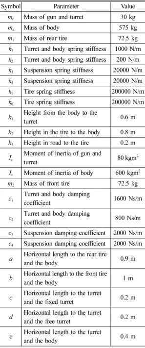
Table 1 Data of parameters for Matlab/Simulink Model
Symbol Parameter Value
m
c
Mass of gun and turret 30 kgm
s
Mass of body 575 kgm
1
Mass of rear tire 72.5 kg k1
Turret and body spring stiffness 1000 N/m k2
Turret and body spring stiffness 200 N/m k3
Suspension spring stiffness 20000 N/m k4
Suspension spring stiffness 20000 N/m k5
Tire spring stiffness 200000 N/m k6
Tire spring stiffness 200000 N/m h1
Height from the body to the
turret 0.6 m
h
2
Height in the tire to the body 0.8 m h3
Height in road to the tire 0.2 mI
c
Moment of inertia of gun and
turret 80 kgm
2
I
s
Moment of inertia of body 600 kgm2
m2
Mass of front tire 72.5 kgc
1
Turret and body damping
coefficient 1600 Ns/m
c
2
Turret and body damping
coefficient 800 Ns/m
c
3
Suspension damping coefficient 2000 Ns/m c4
Suspension damping coefficient 2000 Ns/m a Horizontal length to the rear tireand the body 0.9 m
b Horizontal length to the front tire
and the body 1 m
c Horizontal length to the turret
and the fixed turret 0.2 m d Horizontal length to the turret
and the free turret 0.2 m e Horizontal length to the turret
and the body 0.4 m
(M, K, C)을 임의로 결정하는 것 보다 알려진 상 용차량의 제원을 이용하여 시뮬레이션을 시작하 여 점차 경전투차량의 제원(M, K, C)의 값을 찾아 가는 방식을 선택하였다.
2.1 Matlab/Simulink 구현
반차 모델은 식 (1)과 같은 2계 연립미분방정식 으로 표현된다.
(1) 식 (1)과 같은 미분방정식의 해를 구하기 위해 서는 직접해법과 라플라스 변환을 이용한 대수연 산 후 역 라플라스 변환을 통해 미분방정식의 해 를 구하는 방법이 있다. 하지만 본 논문에서는 Matlab/Simulink로 구현하여 해를 구하기 위해 미 분방정식을 상태방정식으로 바꿔서 계산하는 방 법을 사용하여 해를 구했다.
미분방정식의 각 변수들을 식 (2)와 같이 상태 변수를 설정하였다.
(2) (3)
, ,
식 (2)의 상태변수를 이용하여 미분방정식을 식 (3)과 같은 형태의 상태방정식으로 변환할 수 있다.
(4)
A: State matrix B: Input matrix C: Output matrix
D: Direct transmission matrix
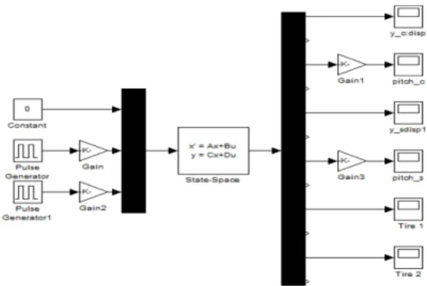
상태방정식(식 (2)~식 (5))을 Matlab/Simulink을 Fig. 2와 같이 구성하여 노면의 요철과 차량의 속 도를 입력 값으로 하여 포의 수직변위와 피치회전 각의 계산하였다.
2.2 포의 수직변위와 Pitch 회전각
차량의 주행시 포의 수직변위와 피치회전각을 알아보기 위한 노면에 두 가지 입력(사각형 요철, 사인파형 요철)을 부가하였다. 차량이 이 노면을 지날 때 발생하는 포의 수직변위와 피치회전을 요 철의 높이 변화 (0.1 m, 0.2 m)와 차량의 속도 변 화(20 km/h, 30 km/h)에 따라 계산했다.
Fig. 3과 Fig. 5은 차량의 속도(20 km/h)로 고정 하고 노면의 요철의 크기를 각각 0.1 m, 0.2 m로 설정했을 때의 포의 수직변위와 피치회전 값이 다. 그 결과 요철의 크기에 비례하여 포의 수직변 위와 피치회전이 발생하는 것을 확인 할 수 있다.
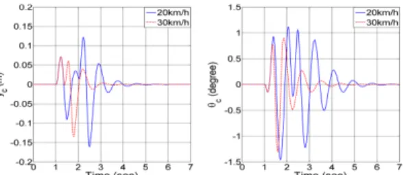
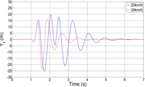
Fig. 4와 Fig. 6은 노면의 요철의 크기를 고정하고 차량의 속도를 20 km/h와 30 km/h로 설정했을 때 의 결과 값이다. 사각형 요철의 경우 20 km/h로 주 행할 때보다 30 km/h로 주행 시 수직변위는 더 크 게 발생하지만 피치회전은 더 작게 회전하는 것을 확인할 수 있었다. 사인파형 요철의 경우에는 최 대 수직변위와 피치회전 둘 다 30 km/h로 주행 시 더 작게 나왔다. 결과적으로 포의 수직변위와 피 MY··( ) CY· t() KY t()t + + =u t( )
x=[x
1
x2
x3
x4
x5
x6
x7
x8
x9
x10
x11
x12
]T
u=[f1
f2
]T
x
1
=yc
, x2
=y·c
, x3
=θc
, x4
=θ·c
x
5
=ys
, x6
=y·s
, x7
=θs
, x8
=θ·s
x
9
=y1
, x10
=y·1
, x11
=y2
, x12
=y·2
x· t( ) Ax t() Bu t= + ( ) y=Cx t( ) Du t+ ( )
Fig. 2 Matlab/Simulink model of half car system model
Fig. 3 The vertical displacement (y
c
) and the pitch angle (θc
) of the gun when the vehicle passes over rectangular bump with 0.1 m and 0.2 m in height respectively at the speed of 20 km/h치회전은 노면의 요철의 크기에 비례하지만 차량 의 속도에 따라서 다양한 형태로 발생하는 것을 확인 할 수 있었다.
3. 강외 탄도 해석
탄도의 해석은 크게 강내 탄도학(Interiror ballistic) 과 강외 탄도학(External ballistic)으로 나눠진다.
강내 탄도학은 추진제의 연소로 발생한 추진가스 의 힘을 받는 동안 강내에서 움직이는 탄자의 운 동특성을 연구하는 운동역학의 한 분야다. 강외 탄
도학은 탄자가 총구 또는 포구를 떠나 어떤 매개 체를 통하여 목표까지 비행하는 동안 탄자의 운동 특성을 연구하는 탄도학의 한 분야이다. 우리는 매 개체가 표준대기일 때 지정된 목표에 대한 탄도의 궤적 해석을 통해 포의 수직변위와 피치회전에 따 른 탄도의 궤도의 변화와 탄착점 오차를 확인한다.
3.1 표준 탄도 이론
항력을 고려한 표준탄도이론을 구체화하기 위 해서 몇 가지 가정이 필요하다. 첫째로 탄도에 작 용하는 외력은 중력과 항력이다. 항력은 압력중심 에 작용하는 힘이지만 편주 각 θ(물체의 운동방향 과 물체 대칭축 사이 각도)이 작을 때에는 항력으 로 인하여 탄도에 걸리는 모멘트가 작기 때문에 이 모멘트는 무시한다. 즉, 항력은 탄도의 중심에 작용한다고 가정한다. 둘째로 중력가속도는 항상 일정하다고 생각한다. 셋째로 지구는 평탄하고 회 전하지 않는다고 가정하며 대기는 표준대기로 생 각한다. 넷째로 탄도의 회전 운동과 이 때문에 발 생하는 마그누스 힘(Magnu s Foce)과 모멘트 (Moment)는 무시한다. 즉, Fig. 7과 같이 탄도에 항력과 중력이 작용한다.
항력과 중력을 반영하여 탄도의 x 축과 y 축에 대한 운동방정식을 세우면 식 (6), 식 (7)과 같이 나타낼 수 있다.
(6)
(7)
여기서 Drag, 와 Bullet weight, , 그리고 Area, 를 대입하여 정 리하면 식 (4)와 같이 나타낼 수 있다.
(8) md
2
xt
2
d---=–Dcosθ
md
2
y t2
d---=–Dsinθ
D 1 2---C
d
ρv2
A=
W=mg A=πd
2
/4d
2
x t2
d --- π---8C
d
d2
---m ρv2
cosθ –= Fig. 4 The vertical displacement (y
c
) and the pitch angle(θ
c
) of the gun when the vehicle passes over rectangular bump with 0.2 m in height at the speed of 20 km/h and 30 km/hFig. 5 The vertical displacement (y
c
) and the pitch angle (θc
) of the gun when the vehicle passes over sinusoidal ground with amplitude of 0.1 m and 0.2m respectively at the speed of 20 km/hFig. 6 The vertical displacement (y
c
) and the pitch angle (θc
) of the gun when the vehicle passes over sinusoidal ground with amplitude of 0.2 m at the speed of 20 km/h and 30 km/hFig. 7 Drag force and gravity force acting on the bullet
(9) 한편, 이고 dy/dt = v
y
= vsinθ 이므로(10)
(11) 위 식 (10)와 식 (11)에서, dx/dt = v
x
, dy/dt = vy
로 놓으면 다음과 같이 4개의 연립 미분방정식으로 대체할 수 있다.(12)
(13)
(14)
(15)
식 (12)~식 (15)을 통해 탄도의 속도와 위치를 구하기 위해 1차 시간적분을 이용하면 다음과 같 이 나타낼 수 있다.
(16)
(17)
(18) (19) 탄환의 사거리는 위 식에서 시간을 매우 작은 시간 간격으로 시간 전진하여 적분함으로써 충분 한 정확도를 얻을 수 있다. 초기조건은 식 (20)과 같다.
, (20)
3.2 탄도 궤적 분석
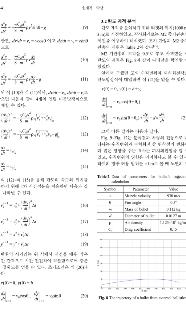
탄도 궤적을 분석하기 위해 타겟의 위치(1000 m, 3 m)로 가정하였고, 직사화기로는 M2 중기관총의 제원을 이용하여 해석했다. 초기 가정과 M2 중기 관총의 제원은 Table 2와 같다
[15]
.M2 기관총의 고각을 0.5
o
로 놓고 사격했을 시 탄도의 궤적은 Fig. 8과 같이 나타남을 확인할 수 있었다.앞에서 구했던 포의 수직변위와 피치회전각을 탄도방정식에 대입하면 식 (21)을 얻을 수 있다.
(21) 그에 따른 결과는 다음과 같다.
Fig. 9~Fig. 12는 분석결과 차량의 진동으로 나 타나는 수직변위과 피치회전 중 탄착점의 변화에 더 많은 영향을 주는 요소는 피치회전임을 알 수 있고, 수직변위의 영향은 미미하다고 볼 수 있다.
타겟의 명중 허용 범위를 ±1 m로 볼 때 노면의 요 d
2
yt
2
d --- π8---C
d
d2
---m ρv
2
sinθ g– –=
dx/ td =v
x
=vcosθd
2
x t2
d --- π8---C
d
d2
---m ρvdxt ---d –
=
d
2
y t2
d --- π8---C
d
d2
---m ρvdyt --- gd – –
=
v
x
dt ---d
⎝ ⎠
⎛ ⎞
n
π 8---Cd
d2
---m ρ v
x 2
+vy 2
vx n
–=
v
y
dt ---d
⎝ ⎠
⎛ ⎞
n
π 8---Cd
d2
---m ρ v
x 2
+vy 2
vy
–g –n
=
x d
t ---d =v
x n
y d
t ---d =v
y n
v
x n 1 +
vx n
dvx
t ---d⎝ ⎠
⎛ ⎞
n
Δt +=
v
y n 1 +
vy n
dvy
t ---d⎝ ⎠
⎛ ⎞
n
Δt +=
x
n 1 +
=xn
+vx n
Δt yn 1 +
=yn
+vy n
Δtx 0( ) 0, = y 0( ) h= x
d t ---d
t 0 =
v
0
cosθ= dy
t ---d
t 0 =
v
0
sinθ=
x 0( ) 0, y 0= ( ) h y= +
c
x d
t ---d
t 0 =
v
0
cos(θ θ+c
)=
y d
t ---d
t 0 =
v
0
sin(θ θ+c
) dyc
t--- dd dθ
c
t ---d
× + +
=
Table 2 Data of parameters for bullet’s trajectory calculation
Symbol Parameter Value
v Muzzle velocity 930 m/s
θ Fire angle 0.5
o
m Mass of bullet 0.112 kg d Diameter of bullet 0.0127 m ρ Air density 1.125×10
3
kg/m3
Cd
Drag coefficient 0.15Fig. 8 The trajectory of a bullet from external ballistics
철을 지난 후 안정화 시간 즉, 사격가능시간은 Table 3을 통해 볼 수 있다.
본 논문에서는 노면의 요철을 한번 지나갈 때의 결과에 대해서 분석했다. 그 결과 요철을 지나갈
때 4초 이내는 사격 시 명중률이 현저히 저하된다 는 것을 확인 할 수 있었다. 지상 전투차량의 설계 에 있어서 이러한 문제점을 해결하기 위해 차량의 제원을 변경하거나 진동을 줄일 수 있는 진동안정 화 장치시스템을 구성해야 한다.
3. 결 론
본 논문은 지상 전투차량이 주행간 사격 시 노 면의 요철에 의한 동역학적 특성이 명중률에 미치 는 영향을 분석했다. 차량의 반차 모델을 사용하 여 다양한 노면과 다양한 속도에 대한 차량의 진 동 해석을 수행하여 포의 조준오차인 수직변위와 피치회전을 구하였다. 계산된 포의 조준오차 오차 와 탄도 궤적 해석을 연계하여 주행 중 사격 시의 탄착점의 변화를 확인하였다. 또한 노면의 요철을 지난 후의 안정화 시간을 확인하여 명중 가능 시 간을 분석하였다. 진동안정화 장치가 없으면 주행 중 사격의 명중률이 현저히 떨어짐을 알 수 있다.
향후 동일한 접근법을 활용하여 도로의 다양한 형 태와 다양한 속력에 대한 명중률 데이터를 수집함 으로써 주어진 도로 주행 조건에서 특정 명중률을 담보해주는 진동안정화 장치의 설계 변수를 결정 Fig. 9 The point of impact on the target when the
vehicle runs over a rectangular obstacle at the speed of 20 km/h (Amplitude is 0.1 m and 0.2m respectively)
Fig. 10 The point of impact on the target when the vehicle runs over a rectangular obstacle whose height is 0.2 m at the speed of 20 km/h and 30 km/h
Fig. 11 The point of impact on the target when the vehicle runs over a sinusoidal road whose amplitude is 0.1 m and 0.2 m respectively at the speed of 20 km/h
Fig. 12 The point of impact on the target when the vehicle runs over a sinusoidal road whose amplitude is 0.2 m at the speed of 20 km/h and 30 km/h
Table 3 Stable time of each situation
Height of an obstacle 0.1 m 0.2 m Velocity
Road type 20 km/h 20 km/h 30 km/h Rectangular 4.26 sec 4.26 sec 3.56 sec Sine 4.25 sec 4.30 sec 3.64 sec
할 수 있다. 향후 연구로서는 전투차량의 해석 시 차량의 발사 반발충격력, 엔진의 진동, 기후 같은 환경 조건을 고려한 명중률 계산이 수행될 수 있다.
감사의 글
본 연구는 한국 국방과학연구소의 지상체계분 석특화연구실 과제의 지원을 받았으며, 이에 감사 합니다.
References
1. Lee, C.H. and Chen, C.L., 1996, Modelling and Simulation of Half Car Suspension System with a MR Damper Using RecurDyn and Simulink, CSME, pp.27-32.
2. Adrian-ioan Niculescu, Dan Dumitriu and Tudor Sireteanu, 2008, Half-Car 2D Model Simulation of the Self-Adjustable VZN Shock Absorber Suspension Behavior, 9th WSEAS Int. Conf. on Acoustics & Music: Theory & Applications, pp.35-40.
3. Suaib, N.M. and Sam, Y.M., 2008, Modeling And Control of Active Suspension Using Pismc And SMC, Journal Mekanikal, pp.119-128.
4. Sun, L. and Luo, F., Nonstationary Dynamic Pave- ment Loads Generated by Vehicles Traveling at Varying Speed, Journal of Transportation Engi- neering, 133(4), pp.252-263.
5. Kang, H.-J. and Kim, J.-H., 2013, Design, Anal- ysis and Experiment of Potato Gun with a Spher- ical Projectile, Journal of the Korean Society for Aeronautical and Space Sciences, pp.796-804.
6. Michael, E., 2006, CT Tractogram: Technique for Demonstrating Tangential Bullet Trajectories, Journal of Trauma-Injury Infection & Critical Care, pp.1362-1363.
7. Daniela Marchetti, Tommaso Tartaglione, Ennio Giovine, 연도, Reconstruction of the Angle of Shot by using Computed Radiography of the Head, American Journal of Forensic Medicine
& Pathology, 24(2), pp.155-159.
8. Tyan, F., Hong, Y.-F., Tu, S.-H. and Jent, W.
S., 2009, Generation of Random Road Profiles, Journal of Advanced Engineering, pp.1373-1378.
9. Park, W., Pack, K. and Kang, H., 2012, Sensi- tivity Analysis of Design Parameters of an Anti- aircraft Gun for Hit Probability Enhancement, Journal of Mechanical Science and Technology, pp.3043-3046.
10. Huseyin Akcay and Semiha Turkay, 2009, Influ- ence of Tire Damping on Mixed H2=H1 Syn- thesis of Half-car Active Suspensions, Journal of Sound and Vibration, 322, pp.15-28.
11. Keith J. Wakeham and D. Geoff Rideout, 2011, Model Complexity Requirements in Design of Half Car Active Suspension Controllers, ASME Dynamic Systems and Controls Conference, Arlington.
12. Esmailzadeh, E. and Fahimi, F., 1997, Optimal Adaptive Active Suspension for a Full Car Model, Vehicle Systems Dynamics, 27, pp.89-107.
14. Butsuen, T., 1989, The Design of Semi-active Suspensions for Automotive Vehicles, Massa- chusetts Institute of Technology.
15. Chris McNab, 2004, The Great Book of Guns, Thunder Bay Press, pp.402.
송 재 복
2014년 명지대학교 기계공학과 학사 2014년~현재 명지대학교 기계공학
과 석사과정
관심분야: Geometric Modeling, CAD/CAM 응용
박 강
1986년 2월 서울대학교, 공학학사 (기계설계학과)
1988년 2월 서울대학교, 공학석사 (기계설계학과)
1996년 8월 The Pennsylvania State University, Ph.D. (Industrial and Manufacturing Eng.)
학회활동현 대한기계학회 교육부문 이사 현 대한기계학회 생산및설계 부문 현 한국정밀학회 종신회원 이사 2013년 3월~현재 한국CAD/CAM학
회 부회장
2010년 3월~2012년 2월 한국CAD/
CAM학회 총무