Fundamental Study of an Integrated Control Method for a Linear Motor Driven Container Crane System
Sangbeak An†⋅Yuki Taniguchi1⋅Shigehiro Yamamoto1⋅Teruo Azukizawa2 (Received October 7, 2009 ; Revised November 11, 2009 ; Accepted November 26, 2009)
Abstract:The authors have proposed a linear motor driven container crane system, in which the linear motor to drive trolley chassis is also used to control swaying motion of a hanging container. To utilize the proposed system, it is needed to develop a power saving control system for the linear drive system. In this paper, an integrated control system to minimize required electric power to drive a trolley chassis with the suppressed swaying motion of a hanged container, is proposed. The validity of the proposed control system is investigated by the simulation using Simulink.
Key words:Container crane, Linear motor, Control system, Simulation.
†corresponding Author (Graduate school of Science and Technology, Kobe University, E-mail : 044d804n@stv.kobe-u.ac.jp, Tel:+81-78-431-6288)
1 Kobe University, Japan 2 Tokyo city University, Japan
1. Introduction
Recently, the huge container carriers of over 14,000TEU class are in operation, according to a rapid increase in worldwide marine transport. Therefor, it is required to develop a higher speed and more reliable container handling system. In the conventional crane system, the trolley chassis are driven by the rotary motors, these are, the driving forces for the trolley chassis are generated by the driving wheels and the iron rail or the driving sheaves and the wires[1]. In these adhesive traction systems, the reliability of the driving forces depend on the conditions of the surfaces of the wheels and rail or the sheaves and wires.
The authors have proposed a container crane system, in which the linear motor to drive trolley chassis is also used to
suppress the swaying motion of a hanged container at the same time[2]-[6]. The primary cores generated travelling magnetic fields are mounted on the trolley chassis, and the secondary reaction plates are installed along the girder. Then, the driving forces can be directly transferred to the trolley chassis even if the surfaces of the suspension wheels and rails are wet or frozen. Then, the linear motor drive systems are expected to realize a reliable container handling system. Furthermore, the steady and high acceleration/
deceleration drive mechanism for the trolley chassis will be able to control the swaying motion of a hanged container at the same time. However, the air gaps between the primary cores and the secondary reaction plates of the linear motor are obliged to be set as the
relatively larger values compared to the conventional rotary motors, considering the accuracy of fabricating suspension mechanisms of the trolley chassis and the safety in the operation. Then, to realize the proposed system, it is needed to develop a power saving linear motor control system to drive the trolley chassis and to suppress the swaying motion of a hanged container at the same time.
In this paper, the authors propose a power saving control system for the proposed integrated trolley drive and swaying motion control system. The validity of the proposed system is estimated simulation.
2. Integrate trolley drive and swaying angle control system
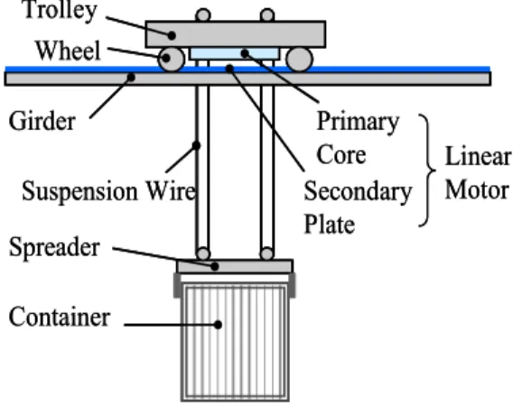
2.1 Composition of the linear motor driven crane system Trolley
Girder
Spreader Container
Primary Core Secondary Plate
Linear Motor Suspension Wire
Wheel Trolley
Girder
Spreader Container
Primary Core Secondary Plate
Linear Motor Suspension Wire
Wheel
Figure 1: Linear motor driven crane system
Figure 1 shows one of the proposed system. The trolley chassis is suspended and guided by the wheels with respect to the rails installed along the girder. A
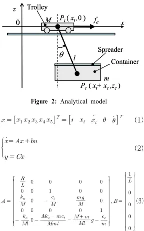
container is clamped by the spreader hanged from the trolley chassis with the sheaves and wires. A linear induction motor, LIM, is used to drive trolley chassis and to control swaying motion of a hanged container, in this system. That is, the primary core of the LIM is installed in the trolley chassis and excited from the V/f controlled 3 phase inverter. The aluminum plate with the back iron are installed along the girder, as the secondary reaction plate of the LIM. As the thrust force generated by the LIM act to the chassis directly, regardless of the adhesive force between suspension wheels and rails, high acceleration or quick thrust control can be realized. Then, the integrated trolley drive and swaying motion control for a hanged container will be realized. Figure 2 shows the analytical model for the proposed system. To simplify the analysis, the total masses of the hanged members, such as a container, the spreader and hanging wires, are assumed to concentrate to the gravity center of the hanged member.
2.2 Control system description
Here, we set the armature current of the LIM , the position and the velocity of a trolley and , the swaying angle and its derivative of the hanged container
and , as the state variables. Then, the stated variable vector and the state equations, derived with the assumption that the magnitude of the swaying angle is small are expressed as follows[5]-[6].
M
l
fa x
z
m 0
Trolley
Container Spreader Pt ( xt,0 )
Pc( xt+ xc,zc) θ
M
l
fa x
z
m 0
Trolley
Container Spreader Pt ( xt,0 )
Pc( xt+ xc,zc) θ
Figure 2: Analytical model
(1)
(2)
(3)Where, M and m the masses of the trolley chassis and the hanged members, is the length of the hanging wire, and are the coefficients of resistance of the suspension wheels of the trolley chassis and sheaves of the hanging wires, R and L are the resistance and the inductance of the armature coils of the LIM, is the armature voltage of the LIM as the input signal for the system. If the state variables can be detected, we can compose the feedback control based on the following expression.
(4)
where, is the feedback
coefficients vector.
Here, we introduce the optimal regulator to realize both quick transportation and suppression of swaying motion of a container. That is, the feedback coefficients are determined to minimize the performance index J expressed as follows.
∞ (5)
Where, Q are the following weighting factors matrix, and r is a weighting factor.
(6)
In this system, position of the trolley x can be detected by a rotary encoder attached to the suspension wheel of the trolley chassis and the swaying angle of the hanged member is estimated by detecting reactive force acting on the trolley chassis using an acceleration sensor attached to the trolley chassis derived from the following expression.
tan
(7) Where, is the output signal of the acceleration sensor attached to the trolley chassis, is the thrust force generated by LIM.In this paper, the magnitude of the electric power fed to the LIM is assumed as proportional to the square of the
armature current of the LIM. So, the objective of the control system design is to minimize the amplitude of the armature current, in which both the required time to transfer container and the maximum swaying angle of a hanged container are made as small as possible.
3. Simulation
3.1 Simulation model
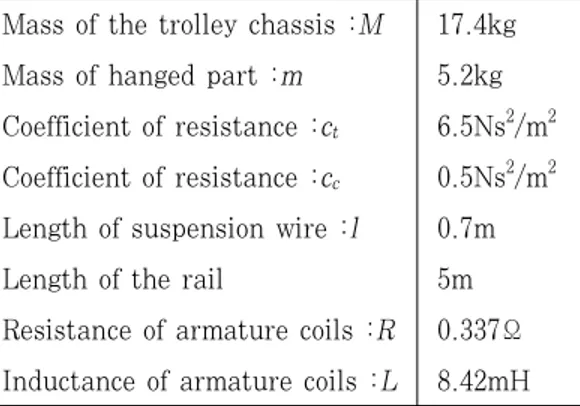
MATLAB/Simulink is used to design the control system. The parameters used in the following simulation are shown in the Table 1. These parameters are for the small scale test facility in our laboratory.
Table 1: Parameters used in the simulation Mass of the trolley chassis :M 17.4kg Mass of hanged part :m 5.2kg Coefficient of resistance :ct 6.5Ns2/m2 Coefficient of resistance :cc 0.5Ns2/m2 Length of suspension wire :l 0.7m
Length of the rail 5m
Resistance of armature coils :R 0.337Ω Inductance of armature coils :L 8.42mH
3.2 Simulated results
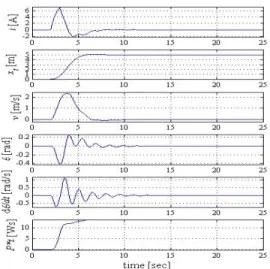
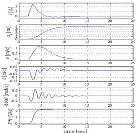
Figure 3 shows the simulated responses for the weighting coefficients(w1, w2, w3, w4, w5, r)=(1, 1, 1, 1, 1, 1). The curves in the following figure are, from top, the armature current of LIM , the position of the trolley chassis , the velocity of the trolley chassis , the swaying angle of the hanged container , and its time derivative . The maximum armature
current is 3.13A, the required time to transfer 5m distance is 7.5sec, the maximum velocity is 1.367m/s, the maximum swaying angle is 0.172rad, and the total energy required to transfer 5m is 3.30Ws, in the responses for the equally weighted control system shown in the Fig 1.
Figure 3: Responses for w1=w2=w3=w4=w5=r=1
Figure 4: Responses for w1=10,w2=w3=w4=w5=r=1
Figure 5: Responses for w2=10,w1=w3=w4=w5=r=1
Figure 6: Responses for w3=10,w1=w2=w4=w5=r=1
Figure 4 shows the simulated responses for the weighting coefficients(w1, w2, w3, w4, w5, r)=(10, 1, 1, 1, 1, 1). In this case, the reference value for the armature currents are set as 0 to minimize required electric power. So, the total energy required to transfer 5m distance is reduced to 0.991Ws.
However, the required time to transfer becomes longer as 13seconds. Then, the weighting factor for the armature current w1 should be set as not so large value.
Figure 7: Responses for w4=10,w1=w2=w3=w5=r=1
Figure 8: Responses for w5=10,w1=w2=w3=w4=r=1
Figure 5 shows the simulated responses for the weighting coefficients(w1, w2, w3, w4, w5, r)=(1, 10, 1, 1, 1, 1). Because the reference value for the position is set as step function, the required time to transfer 5m distance becomes to the minimum value of 4seconds. However, the armature currents becomes large as 6.96A, and the total energy required to transfer 5m distance becomes large as
13.62Ws. The swaying angle of the container is also large as 0.405rad. Then, the weighting factor for the position w2
should be set as small value if the reference is given as step signal.
Figure 6 shows the simulated responses for the weighting coefficients(w1, w2, w3, w4, w5, r)=(1, 1, 10, 1, 1, 1). The maximum armature current is 2.58A, and the total energy required to transfer 5m is reduced to 1.912Ws. However, the required time to transfer 5m distance is large as 23seconds. Then, the weighting factor for the swaying angle w3 should be set as small value if the required time to transfer 5m distance is considered as an important item.
Figure 7 and 8 show the simulated reponses for the weighting coefficients (w1, w2, w3, w4, w5, r)=(1, 1, 1, 10, 1, 1), (1, 1, 1, 1, 10, 1), respectively. The maximum armature currents and the total energy required to transfer 5m are not so changed compared to Figure 3. However, the settling time for swaying motion of the container becomes small as 4 seconds in case of the Figure 8. Then the weighting factor for the deviation of the swaying angle should be set as large value.
Figure 9 shows the simulated responses for the weighting coefficients (w1, w2, w3, w4, w5, r)=(1, 1, 1, 1, 1, 10). In this case, the total electric energy required to transfer 5m distance become low as 2.32Ws, however, the settling time for the swaying motion is larger than the other case.
Figure 10 shows the simulated responses for the weighting coefficients (w1, w2, w3, w4, w5, r)=(1, 1, 1, 10, 10, 1).
In this case, the maximum armature current is 2.81A, the required time to transfer 5m distance is 7 seconds, the maximum velocity is 1.348m/s, the maximum swaying angle is 0.147rad, and the total energy required to transfer 5m is 3.16Ws. The expected control system to realize both high speed transfer and suppression of the swaying motion of the hanged container are realized in this case.
Figure 9: Responses for r=10,w1=w2=w3=w4=w5=1
Figure 10: Responses for w4=w5=10,w1=w2=w3=r=1
4. Conclusions
The power saving control system in the integrated trolley drive and swaying angle control system for the linear motor driven container crane system is proposed. The parameters for the optimal regulator control system are designed using MATLAB/Simulink. In the sense of power saving trolley drive with reduced swaying motion of the hanged container, we can obtain an optimum feedback coefficients based on the optimum regulator, for the numerical model of the small test facility in our laboratory.
The validity of the simulated results described in this paper will be shown by the experimental results using the small scale test facility in our laboratory, soon.
Further investigations considering the restrictions in the power source such as the current limit will also be made in the near future.
References
[1] S. B. An, et al., “A new approach to anti-sway system design for a container crane”, SICE Annual Conference, Fukui, Japan, pp. 335-339, 2003.
[2] Y. Taniguchi, S. B. An, K. Maegaito, and T. Azukizawa, “Conceptual design of linear motor driven container crane system”, LD-06-69, Technical Meeting on Linear Drives, IEEK, (in Japanese), 2006..
[3] Y. Taniguchi, S. B. An, H. K. Wan, S.
Yamamoto and T. Azukizawa,
“Integrated control method for linear motor driven container crane system”, PS2-11, Proc. of the 6th Int. Symp. on
Linear Drives for Industrial Applications, LDIA2007, Lille, France, pp.35-36, 2007.
[4] Y. Taniguchi, S. B. An, H. K. Wan, H.
Makino, S. Yamamoto, and T.
Azukizawa, "Fundamental study of an integrated control method for a linear motor driven container crane system", Int. Conf. Elec. Eng., 2008, ICEE2008, Okinawa, O-060, 2008.
[5] Y. Taniguchi, S. Teramura, S. B. An, S.
Yamamoto, and T. Azukizawa, “A study on swaying angle control for linear motor driven contianer crane system”, Technical Meeting on Linear Drives, IEEJ, LD-09-02, (in Japanese), 2009.
[6] Y. Taniguchi, S. B. An, S. Yamamoto, T. Azukizawa, “Integrated and trolley drive and swaying angle control system for a linear motor driven container crane system”, The 7th Int. Symp. on Linear Drives for Industry Applications, LDIA2009, Inchon, Korea, 2009.
Author Profile
Sangbeak An
He received B.S and M.S degrees from Kunsan National University, Korea, in 2001 and 2004, respectively.
He is currently a doctoral student at Kobe University. His research interests include application with Linear motor driven crane control system design.
Yuki Taniguchi
He received B.S and M.S degrees from Kobe University, Japan, in 2003 and 2005, respectively. He is currently a doctoral student at Kobe University. He is currently a doctor course student of the same college. He is engaged in research on linear motor driven crane control system design.
Shigehiro Yamamoto
He received his B.E, M. E and D.E degrees in electrical engineering from Kyoto University in 1990, 1992 and 1997, respectively. He joined Kobe University of Mercantile Marine in 1997.
Since 2007, he has been an associate professor on the Graduate School of Maritime Sciences, Kobe University. His research interests include autonomous navigation of a mobile robot with machine vision and precise 3D measurement of ships.
Teruo Azukizawa
He received his B.S, M.S and Dr. Eng.
degrees from Waseda University, Japan, in 1969, 1971 and 1994, respectively. He joined Toshiba Corp., in 1971, and engaged in the magnetically levitated super high speed railway system project. He moved to a professor in Kobe University of Mercantile Marine, in 2002. He is currently a professor at the faculty of engineering in Tokyo City University, Japan. His research interests are linear drive system, magnetic levitation, marine engineering, et al.