J. Korean Soc. of Marine Engineering (JKOSME) ISSN 2234-8352 (Online)
http://dx.doi.org/10.5916/jkosme.2014.38.8.961 Original Paper
†Corresponding Author (http://orcid.org/0000-0002-6132-0636): Mechanical Part Technology Center, Korea Testing Laboratory, Sa-dong, Sangnok-gu, Ansan-si, 426-910, Korea, E-mail: [email protected], Tel: 031-500-0407
1 Global Core Research Center, Pusan National University, E-mail: [email protected], Tel: 051-510-2385
Optimum seat design for the quadruple offset butterfly valve by analysis of variance with orthogonal array
Sang-Beom Lee1 ․ Dong-Myung Lee†
(Received September 30, 2014; Revised October 15, 2014;Accepted October 27, 2014)
Abstract: In onshore and offshore plant engineering, a broad use of pipe system have been achieved and accordingly related technologies has been developed especially in the field of flow control valves. The aim of this study is to suggest the quad- ruple offset butterfly valve for bi-directional applications which show equivalent operating torque characteristics of the triple offset butterfly valve. Seat design parameters for the quadruple offset butterfly valve are determined by the proposed method utilizing both ANOVA (analysis of variance) and the orthogonal array. Through additive model considering the effect of design parameters on seating torque, mean estimation is performed and thus its optimization results are verified by design of experi- ment results. The insight obtained from the present study is beneficial for valve design engineers to develop reliable and in- tegrated design of the quadruple offset butterfly valve.
Keywords: Butterfly Valve, Quadruple Offset, Analysis of Variance (ANOVA), Orthogonal Array, Optimization
1. Introduction
With advancement of industrialization, facilities in industries are likely to diversify and become more complex. Accordingly, offshore and onshore plant industries tend to focus on not only improving productivities together with reducing production costs but also maintaining and managing the uniformity of products through enhancing energy efficiencies and simplifying processes with automatic control between components.
Offshore and onshore plants are aimed at manufacturing products as inter-connected systems with a variety of control loops. In order to ensure the quality of the products, each con- trol loop must work for limiting the main drivers including pressure, flow, water level, temperature, etc. within the allow- able range of each parameter [1]. Equipment and devices in- stalled in plants should be provided various sources including material, energy, and information enabling them efficiently. In this regard, pipelines play an important role to deliver material and energy from one device to another and the control of their function is mainly dependent on the valve system.
Furthermore, it is found that they are essential components transporting various fluids in ships although pipelines are rela- tively small compared with the cooling system built in onshore plants such as desalination plants, chemical plants, nuclear and thermal power plants.
Recently, the design requirements related to temperature,
pressure, and flow rate, etc. are likely to become more and more severe due to the trend of larger plants and production facilities. At present, either of a globe valve or gate valve is widely spread for control high-pressure. According to the pre- vious researcher [2][3], the number of applications of both butterfly and ball valves are expected to gradually continue to rise due to the issues such as high cost and low maintain- ability of these valves.
Until now, numerical studies related to the butterfly valve were mainly conducted for examining their performance in- cluding the loss coefficient of the valve, torque characteristics, flow control characteristics and the structural reliabilities [4][5]. With respect to the concentered butterfly valve, the characteristics of the valve is numerically assessed based on the structural and flow analysis in order to ensure the struc- tural reliability and the flow stability and therefore an opti- mum design of the valve disc was performed by the orthogo- nal array [5][6]. Further, the study of the pressure drop and cavitation characteristics was carried out for the concentered butterfly-type valve [7]. For the offset butterfly valve, Park et al. [8] focused on the effect of the eccentric shaft on the in- ternal flow characteristics and Lee et al. [9] analyzed the flow characteristics with varying shape of the seat.
For the studies associated with butterfly valves, since they were designed in accordance with ANSI B 16.34 Class
150~300 which was designed for low-pressure. It is hard to find track records in the high-pressure which causes severe structural deformation to the disc, detachment of the seat and non-applicability of the reverse direction. In this regards, Lee and Kim [10] proposed the quadruple offset butterfly valve which is keeping advantages of triple offset butterfly valve with improving reversal performance and identified sensitivities of each parameter based on the parametric studies in order to ensure the applicability under high-pressure.
The purpose of this study is to define design range of the main parameters for the seat and to optimize the shape of the seat in association with seating torque of the quadruple offset butterfly valve which is capable of applying bi-directional applications. By applying ANOVA and orthogonal array for the seat optimization, sensitivities for design parameter are identified and compared with the results of mean estimation.
The mean estimation of seating torque is evaluated by the ad- ditive model considering the main effects of each design pa- rameter and validated by comparison with the analysis results.
2. Quadruple Offset Butterfly Valve
The butterfly valve can be divided into two types in aspect of operating axis. Concentric type and offset type whether the disc aligns with rotating axis depending on the structure of the seat. There are two offset valves are mostly used which named as double and triple eccentric offset butterfly valve. According to the structure of offset in the valve, the operating torque characteristic is significantly varies according to the flow in- duced pressure differences between upstream and downstream of the pipeline. However, for valves under operating con- ditions, seating torque required to open the closed valve disc separating from the seat is the most important factors affecting the valve performance and its effect on the disc becomes more significant when it is fully closed. Therefore, the most im- portant factor in design of a driving part of valves is to dimin- ish seating torque acting on the seat itself. As a result, a vari- ety of seat configurations has been proposed in terms of re- ducing seating torque.
Figure 1 describes a comparison example of the seating tor- que ratio for double and triple offset butterfly valves in terms of disc opening angles. It is observed that seating torque of triple offset valves in low opening angles varies more dramati- cally than the double offset valves due to the effect of the changing contact type from a surface to a line [11]. However, it has been recognized that the triple offset butterfly valve shows weak performance for the reverse direction because of the applied contact type which is only able to seal the leakage
by line type.
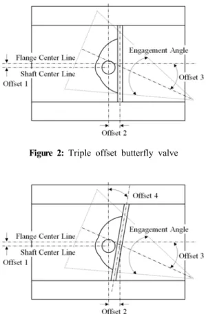
Figure 2 shows schematic representation of the triple offset butterfly valve. Using the triple offset butterfly valve in re- verse direction, when the engagement angle is large, the leak- age is more likely to happen, and on the other hand, when the angle is relatively small, the durability of seat could drop due to the significant increment in torque. To tackle these issues, Lee and Kim [10] proposed the new quadruple offset butterfly valve applying offset for the seat as shown in Figure 3.
According to their results, it was expected to improve the valve performance in reverse direction with keeping the bene- fits of the triple offset valve.
Figure 1: Seating torque characteristics of butterfly valve
Figure 2: Triple offset butterfly valve
Figure 3: Quadruple offset butterfly valve
3. Optimization Algorithm
In the present study, the optimization algorithm is developed based on the structural analysis, the orthogonal array and ANOVA, and the detail of each step is as follows:
Step 1. Definition and selection of object values
Step 2. Determine design parameters, the number of level and their values
Step 3. Selection of orthogonal array and allocation of de- sign parameters considering overall degrees Step 4. Executing design of experiment and calculating ob-
ject values according to the combinations of design parameters determined by the orthogonal array Step 5. Calculating mean of object values for each level of
design parameters
Step 6. Selection of significant factors influencing most on the object values based on the results of ANOVA Step 7. Determining optimum design conditions resulting
from the mean estimation
Step 8. Estimation of the object values for significant factors under optimum design conditions by additive model Step 9. Implementing confirmation experiment and estimat- ing real object values under optimum design con- ditions
Step 10. Determining optimum design conditions as an opti- mum solution based on the validation of additivity Step 11. If the additivity of the additive model is not met
for the criteria, back to the Step 4 in consideration of developing new orthogonal array of selection of the design parameters, adjusting the level range and including the interaction term and perform all the steps accordingly.
4. Optimization Seat Configuration
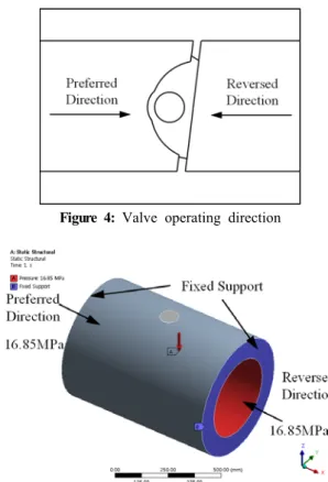
The aim of this chapter is to analyze the relation between each design parameter and seating torque for the quadruple offset butterfly valve. By using finite element method compu- tation, torque of the shaft is numerically calculated in terms of rotational directions, here preferred and reverse directions. In the present study, the fluid flow from left to right is defined as the preferred direction as shown in Figure 4. Applied boun- dary conditions of the finite element method computation are shown in Figure 5. It is assumed that both ends of valves are fixed and the load, 16.85 MPa is applied for the inside of Class 900. To apply the contact condition between the disc and the body of the seat, “No separation” contact condition is applied. The “Bond” contact condition is applied for the valve body and the disc with their stems.
Figure 4: Valve operating direction
Figure 5: Boundary condition for experiment
4.1 Determining design parameters
In the present study, 5 design parameters for the quadruple offset butterfly valve are defined as shown in Figure 6. The detail is as follows.
- Parameter 1: Offset between flange and shaft center lines (fixed at 10.0mm)
- Parameter 2: Offset between seat and shaft center lines (fixed at 47.5 mm)
- Parameter 3: Offset between flange center line and seat angle
- Parameter 4: Angle offset between shaft center line and seat center line
- Parameter 5: Engagement angle of seat
The configuration optimization is carried out for parameters 3, 4 and 5.
Park [12] noted that in order to identify linear and nonlinear effect, level 2 and 3 of the design parameter are proper, respectively. In the present study, level 3 is applied. Table 1 represents the level of each design parameter based on the de- termined results along with the maximum and minimum rang- es at which no physical interference. To analyze interactions among parameters, 3 design parameters with 3-level by using the orthogonal array of full factorial experiment are defined and summarized in Table 1. Table 2 shows the numerical
Figure 6: Quadruple offset butterfly valve design parameters
Table 1: Design parameters and levels
Design Parameter Leval
Symbol Description Unit 1 2 3
A Offset 3 deg. 12 15 18
B Offset 4 deg. 1 4 7
C Engagement angle deg. 8 14 20
Table 2: Orthogonal array design and the experimental results
Run A B C
Response (kN·m)
Preferred Direction
Reverse Direction 1
1 1
1 11.06 10.76
2 2 10.22 9.91
3 3 9.55 9.32
4
2
1 11.04 10.65
5 2 10.1 9.72
6 3 9.37 9.09
7
3
1 11.04 10.56
8 2 10 9.52
9 3 9.21 8.88
10
2 1
1 10.69 10.43
11 2 9.91 9.66
12 3 9.3 9.11
13
2
1 10.64 10.32
14 2 9.79 9.49
15 3 9.13 8.91
16
3
1 10.62 10.21
17 2 9.68 9.31
18 3 8.98 8.72
19
3 1
1 10.27 10.05
20 2 9.56 9.36
21 3 9 8.86
22
2
1 10.21 9.94
23 2 9.44 9.2
24 3 8.84 8.67
25
3
1 10.17 9.83
26 2 9.34 9.04
27 3 8.7 8.51
results of in accordance with the design parameters determined by the orthogonal array of full factorial experiment.
4.2 Analysis of variance (ANOVA)
ANOVA results for torque in terms of the level average are presented in Table 3. It is found that the maximum difference (∆) between average levels in mean estimation shows C, A and B order.
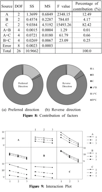
Figure 7 summarizes the mean response in terms of parameter levels. It is observed that the slope according to the level change as depicted in Table 3 is relatively large in design pa- rameter C which shows the most influential design parameter on the seating torque. In order to analyze the significant factors in seating torque, ANOVA is implemented and the results are pre- sented in Table 4 and Table 5 in terms of design parameters. As a result, design parameter C shows the most significant factor from the value and contribution ratio of parameters. Figure 8 displays the level of contribution among design parameters.
Figure 9 shows the results of interaction effect between design parameters and it shows that effect is insignificant.
Table 3: Mean effect response table
Level Preferred Direction Reverse Direction
A B C A B C
1 10.178 9.953 10.638 9.824 9.717 10.305
2 9.860 9.839 9.783 9.572 9.554 9.468
3 9.504 9.750 9.121 9.273 9.398 8.896
△ 0.673 0.202 1.518 0.551 0.319 1.409
Rank 2 3 1 2 3 1
Figure 7: Mean effect response graph
Table 4: ANOVA results table for preferred direction
Source DOF SS MS F value Percentage of
contribution (%)
A 2 2.0425 1.0212 4000.35 15.99
B 2 0.1851 0.0925 362.51 1.45
C 2 10.4246 5.2123 20417.55 81.64
A×B 4 0.0003 0.0001 0.26 0
A×C 4 0.0670 0.0168 65.64 0.52
B×C 4 0.0501 0.0125 49.04 0.39
Error 8 0.0020 0.0003
Total 26 12.7695 100.0
Table 5: ANOVA results table for reverse direction
Source DOF SS MS F value Percentage of
contribution (%)
A 2 1.3699 0.6849 2348.15 12.49
B 2 0.4574 0.2287 784.05 4.17
C 2 9.0384 4.5192 15493.26 82.42
A×B 4 0.0015 0.0004 1.29 0.01
A×C 4 0.0721 0.0180 61.79 0.66
B×C 4 0.0269 0.0067 23.09 0.25
Error 8 0.0023 0.0003
Total 26 10.9662 100.0
(a) Preferred direction (b) Reverse direction Figure 8: Contribution of factors
Figure 9: Interaction Plot
Table 6: ANOVA results for preferred direction : without interaction effect
Source DOF SS MS F value
A 2 2.0425 2.0425 1.0212
B 2 0.1851 0.1851 0.0925
C 2 10.4246 10.4246 5.2123
Error 20 0.1194 0.1194 0.006
Total 26 12.7715
Table 7: ANOVA results for reverse direction : without interaction effect
Source DOF SS MS F value
A 2 1.3699 1.3699 0.6849
B 2 0.4574 0.4574 0.2287
C 2 9.0384 9.0384 4.5192
Error 20 0.1029 0.1029 0.0051
Total 26 10.9685
4.3 Determining optimum design parameters
Since the optimum conditions of significant factors minimiz- ing seating torque is a combinations of both ends, according to the results of mean estimate, the design parameters of A, B and C with 3-level, would be the optimum conditions. To ap- ply for the additive model, ANOVA is conducted for design parameters of A, B, and C without interaction effect by the orthogonal array. The results are presented in Table 6 and Table 7. Mean estimation of seating torque within optimum design conditions is predicted by additive model using Equation (1) considering main effects of significant factors.
(1)
Where, is the mean of in Table 2 represents the results of measured seating torque for experiment simulations in terms of directions. And is number of design parameters and is the mean of torque in the optimum condition for ith design parameter. Selected optimum design condition is the same as
"Run 27" of the orthogonal array. The additivity of additive model is validated by the seating difference between prediction and experiment. The prediction is estimated based on the 95%
of confidence interval of the population mean. The population mean is calculated by Equation (2), it is confirmed that the difference, is within the error limit [13].
(2)
×
(3)
Where is degree of error, is confidence coefficient (1 - confidence interval), is variance of error and is sig- nificant number variation. And is number of experiment data in each parameter and is number of total experiment data.
4.4 Results of Optimum seat design
For alternative of selected model, it is unable to implement for seat interaction in practical cases. In order to settle down this problem, the engagement angle is adjusted and therefore the interaction effect is eliminated. Table 8 summarizes the se- lected optimum design conditions. Under selected conditions, mean estimation of the seating torque using additive model are developed by a form of prediction equation suggested Equation (1). Table 2 shows the mean of measured seating
torque, in experiment simulation for each direction. deg represents the prediction values at 25 degrees resulting from the 2nd order regression analysis for mean estimation of de- sign parameter, C in Table 3.
Table 8: Optimum values of design parameters
Design Parameter Unit Value
Offset 1 mm 47.5
Offset 2 mm 10.0
Offset 3 deg. 18.0
Offset 4 deg. 7.0
Engagement Angle deg. 25.0
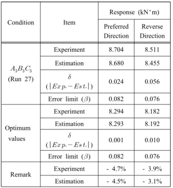
A validation experiment is implemented according to the fi- nal optimum design conditions and their results are 8.924 kN·m for preferred direction and 8.182 kN·m for reverse direction. Table 9 summarizes the experimental results of opti- mum seat design. Seating torque shows reduction in 4.7% for preferred direction and in 3.9 % for reverse direction com- pared to the optimal design. Furthermore, the additivity of ap- plied additive model in optimal model prediction is verified by using not only the difference of seating torque between the es- timated and actual torque at optimum design conditions but al- so the 95% confidence interval. The difference of seating tor- que between the estimated and the actual torque for both di- rections is proved within the error limit of the population mean calculated from the Equation (2) and Equation (3).
Table 9: Experimental results of optimum seat design
Condition Item
Response (kN·m)
Preferred Direction
Reverse Direction
(Run 27)
Experiment 8.704 8.511
Estimation 8.680 8.455
( ) 0.024 0.056 Error limit () 0.082 0.076
Optimum values
Experiment 8.294 8.182
Estimation 8.293 8.192
( ) 0.001 0.010 Error limit () 0.082 0.076
Remark Experiment - 4.7% - 3.9%
Estimation - 4.5% - 3.1%
5. Conclusion
The aim of this study is to define design range of the main parameters for seat and to optimize the shape of the seat in association with seating torque of quadruple offset butterfly valve capable of bi-directional applications.
Based on the results obtained from the present study, the following conclusions can be drawn.
1. Design parameters for the quadruple offset butterfly valve are identified by orthogonal array and ANOVA and there- fore it is observed that the engagement angle is the most influential parameter. Further, it is noted that the inter- action effect among design parameters for representing the shape of the seat are negligible.
2. Using optimization algorithm utilizing orthogonal array and ANOVA, optimization of seat configuration for the quadruple offset butterfly valve is carried out. As a result, the design parameter without interference is determined and the reduction of seating torque is found 4.7 % and 3.9% in preferred and reverse directions, respectively.
3. At present study, the optimization is only taking into ac- count the seating torque as an objective function.
However, it is necessary to consider the hydrodynamic torque. In near future, to establish the validity of the pro- posed method, the actual product will be manufactured and tested.
Acknowledgement
This work was supported by the National Research Foundation of Korea (NRF) grant funded by the Korea gov- ernment (MSIP) through GCRC-SOP (No. 2011-0030013).
References
[1] Fisher, Control Valve Handbook, 4th ed., Iowa, USA:
Emerson Process Management, 2005.
[2] D. G. Kim and J. H. Kim, “A study on structural analysis of globe valve for LNG carrier,” Journal of the Korean Society of Marine Engineers, vol. 31, no.
8, pp. 1013-1019, 2007 (in Korean).
[3] H. S. Jung, Y. H. Kim, J. R. Cho, J. H. Kim, J. R.
Kim, and J. H. Park, “A study on structural design of cryogenic miniature globe valve using finite element method,” Journal of the Korean Society of Marine Engineers, vol. 31, no. 4, pp. 343-349, 2007 (in Korean).
[4] J. U. Lee, D. H. Lee, and Y. H. Choi, “Numerical analysis of incompressible and compressible flow around a butterfly valve,” Journal of Energy
Engineering, vol. 11, no. 1, pp. 26-33, 2002 (in Korean).
[5] Y. C. Park, J. H. Kang, J. M. Lee, and J. Kang,
“Optimization of butterfly valve’s disc using the DACE model based on CAE,” Journal of Ocean Engineering and Technology, vol. 20, no. 3, pp.
96-102, 2006 (in Korean).
[6] X. G. Song, L. Wang, S. H. Baek, and Y. C. Park,
“Multidisciplinary optimization of a butterfly valve,”
ISA Transactions, vol. 48, no. 3, pp. 370-377, 2009.
[7] K. Ogawa and T. Kimura, “Hydrodynamic character- istics of a butterfly valve - Prediction of torque char- acteristics,” ISA Transactions, vol. 34, no. 4, pp.
327-333, 1995.
[8] S. M. Park, H. K. Choi, and G. J. Yoo, “Study on flow characteristics for eccentric shaft in the butterfly valve system,” Proceedings of Korean Society for Computational Fluid Engineering Spring Conference, pp. 587-591, 2011 (in Korean).
[9] J. W. Lee, H. K. Choi, and G. J. Yoo, “Characteristic of butterfly valve flow with different design factors,”
Journal of Computational Fluids Engineering, vol. 15, no. 1, pp. 64-70, 2010 (in Korean).
[10] D. M. Lee and S. Y. Kim, “Sensitivity analysis of design parameters for quadruple offset butterfly valve by operating torque,” Journal of Ocean Engineering and Technology, vol. 28, no. 2, pp. 160-166, 2014 (in Korean).
[11] Tomoe Valve Co.,Ltd, http://www.tomoevalve.co- m/english/digital_catalog/pdf/general_catalogue.pdf, Accessed January 11, 2014.
[12] G. J. Park, “Design of experiments,” Analytic Methods for Design Practice, Berlin, Germany:
Springer, pp. 325-339, 2007.
[13] M. S. Phadke, Matrix Experiments Using Orthogonal Arrays, Quality Engineering Using Robust Design, New Jersey, USA: PTR Prentice Hall, pp. 41-66, 1989.