1. 서 론
인더스트리 4.0은 독일의 국가과학기술 육성정책인 하이테크 전략 2020의 일환으로 2012년 추진된 제조업 혁신 정책으로 사물인터넷과 같은 최첨단 ICT와 제조업 의 융합을 통한 ‘제조업의 완전한 자동생산 체계를 구축
a. Corresponding author; [email protected] Copyright ©2017 KIEEME. All rights reserved.
This is an Open-Access article distributed under the terms of the Creative Commons Attribution Non-Commercial License (http://creativecommons.org/licenses/by-nc/3.0) which permits unrestricted non-commercial use, distribution, and reproduction in any medium, provided the original work is properly cited.
하고 모든 생산 과정이 최적화’됨을 의미한다 [1]. 이를 위해 PLC (programmable logic controller)는 정해진 시간의 제약 안에서 생산설비 제어 프로그램에 따른 실 행 결과 값을 도출해야 하는 실시간성과 설치, 구성, 공 정 변경이 용이한 특징을 가진다. 또한 기존 릴레이 제 어반 대비 높은 경제성을 가진 PLC와 필드버스 기술 또 는 WPAN (wireless personal area network), WLAN (wireless local area network)의 무선통신 기술을 접 목시키기 위한 연구가 활발히 이루어지고 있다 [2-7].
하지만, PLC의 장점과 필드버스 및 무선통신 기술에도 불구하고 스마트팩토리를 위한 소규모 제어시스템을 구
스마트팩토리 구축을 위한 다중 무선통신 컨트롤러 개발
오재준1, 최성주2, 김진사3,a
1 한국기술교육대학교 메카트로닉스공학과
2 한국기술교육대학교 기계공학부
3 조선이공대학교 메카트로닉스과
Development of Multiple Wireless Communication Controller for Smart Factory Construction
Jae-Jun Oh
1, Seong-Ju Choi
2, and Jin-Sa Kim
3,a1 Department of Mechatronics Engineering, Korea University of Technology and Education (KOREATECH), Cheonan 31253, Korea
2 Department of Mechanical Engineering, Korea University of Technology and Education (KOREATECH), Cheonan 31253, Korea
3 Department of Mechatronics, Chosun College of Science & Technology, Gwangju 61453, Korea
(Received July 28, 2017; Revised August 6, 2017; Accepted August 8, 2017)
Abstract: Due to recent industry 4.0, manufacturing has changed a lot. In particular, it is necessary to control the controller and controller of the control system, to communicate various production information and measurement information, and to produce a database in accordance with the flexible production for a small quantity of various items, and to manage the trend of major parts of production facilities. In this paper, we developed a multiple wireless communication controller for small scale control system for smart factory by applying XBee and microcomputer. This controller is cheap and easy to build multi-radio communication environment of 1: N and can control and monitor control system. In addition, we tested multiple wireless communication controllers by using signal processing device and C++, and constructed network, control, and database for mechanism module, and confirmed effectiveness for industrial application.
Keywords: Wireless communication, Controller, Network, XBee, Mechanism
DOI: https://doi.org/10.4313/JKEM.2017.30.9.602 ISSN 1226-7945(Print), 2288-3258(Online)
축할 경우 컨트롤러의 높은 비용, 모듈형 PLC 사용에 따른 큰 부피, PLC 제조회사마다 다른 프로그램 개발 환경, PLC 네트워크 구축을 위한 고가의 통신카드 취 부와 이기종 컨트롤러 제어 등의 어려움이 발생한다.
또한 스마트팩토리 구축을 위해서는 데이터베이스 생 성이 필수적이다.
따라서 본 논문에서는 스마트팩토리 구축을 위해 다 양한 컨트롤러간의 연계를 위한 범용 프로토콜 적용, 1:N의 네트워크 구축, 제어 프로그램과 데이터베이스 생성이 가능한 다중 무선통신 컨트롤러를 개발하여 스 타 네트워크를 구성하고 메커니즘 모듈 제어 및 데이터 베이스를 생성함으로써 스마트팩토리 구축을 위한 컨트 롤러의 유효성을 확인하고자 한다.
2. 실험 방법
2.1 무선통신 기술표준 비교 및 선정
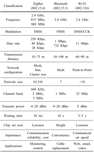
WPAN은 제한된 전력으로 데이터를 전송하고 필요 한 어플리케이션을 무선으로 연결하기 위한 저렴하고 사용이 용이한 무선통신 기술표준이다. 표 1은 IEEE 802 에서 분류되는 대표적인 근거리 통신 기술인 ZigBee, Bluetooth, Wi-Fi를 비교하였다.
다중 무선통신 컨트롤러는 IEEE 802.15.4의 물리계 층과 MAC계층에 준거하여 개발된 ZigBee 기술표준을 적용하였다. 표 2는 ZigBee의 주파수 대역별 특징이며, 그림 1은 ZigBee의 stack 구조이다. 네트워크 구축을 위한 ZigBee의 구성요소는 그림 2에 나타내었다 [8-10].
개발된 다중 무선통신 컨트롤러의 주파수는 2.4 GHz 대 역을 사용하고 각각의 구성요소는 ZigBee coordinator 의 역할을 수행할 수 있도록 하였다.
Fig. 1. Stack structure of ZigBee.
Classification ZigBee (802.15.4)
Bluetooth (802.15.1)
Wi-Fi (802.11b)
Frequency
2.4 GHz, 915 MHz, 868 MHz
2.4 GHz 2.4 GHz
Modulation DSSS FHSS DSSS/CCK
Data rate
250 Kbps, 40 Kbps,
20 Kbps
1 Mbps,
732 Kbps 11 Mbps Transmission
distance 10~75 m 10~100 m 60~90 m
Network configuration
Mesh, Star, Cluster tree
Mesh Point-to-Point
Network size 65,536 7 <10
Channel band
600 KHz, 2 MHz, 5 MHz
1 MHz 22 MHz
Transmit power -4~20 dBm 0~20 dBm 0 dBm
Waiting time 30 ms 10 s 3~5 s
Chip set cost Lowness Height Lowness
Importance Communication
reliability, cost Convenience Communicati on speed Applications Monitoring,
control
Cable replacement
Web, email, video Table 1. Wireless communication technology standard comparison of IEEE 802.
Classification 2.4 GHz 915 MHz 868 MHz
Data rate 250 Kbps 40 Kbps 20 Kbps
Channel 11~26 10 1
DSSS 32 - chip PN
code 15 - chip PN code
Symbol rate 62.5 Ksym/s 40 Ksym/s 20 Ksym/s Chip rate 2.0 Mchips/s 600 Kchips/s 300 Kchips/s
Sensitivity -85 dBm - -
Transmit
power 0d Bm (1 mW)
Table 2. Characteristics of ZigBee by frequency band.
Fig. 2. Network configuration of ZigBee.
2.2 XBee 무선모듈 규격
IEEE 802.15.4에 기반한 XBee는 무선통신 네트워크를 구성할 수 있다. sleep모드에서는 10 uA 이하의 전력강하 를 지원한다. 표 3은 적용된 XBee의 규격이며, 그림 3에 XBee의 내부 데이터 흐름을 나타내었다 [8,11].
Specification XBee
Indoor/Urban range up to 100 ft. (30 m) Outdoor RF line-of-sight range up to 300 ft. (100 m) Transmit power output
(software selectable) 1 mW(0 dBm)
RF data rate 250,000 bps
Serial interface data rate (software selectable)
1200~115200 bps (non-standard baud rates
also supported)
Supply voltage 2.8~3.4 V
Transmit current 45 mA (3.3 V)
Idle/Receive current 50 mA (3.3 V)
Operating frequency ISM 2.4 GHz
Table 3. Specification of XBee.
Fig. 3. Internal data flow diagram of XBee.
2.3 다중 무선통신 컨트롤러 미들웨어 설계
다중 무선통신 컨트롤러는 그림 4와 같이 XBee의 ID 설정에 따라 2⁵ 개의 그룹과 각 그룹마다 2⁴ 개의 컨트 롤러를 확장하여 네트워크를 구성할 수 있도록 미들웨 어를 설계하였다. 그림 5에는 설계한 미들웨어의 신호 흐름을 나타내었다.
Fig. 4. Network configuration of multiple wireless communication controllers.
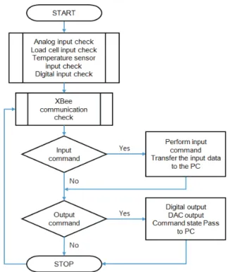
Fig. 5. Middleware signal flow of multiple wireless communication controller.
2.4 다중 무선통신 컨트롤러 제작
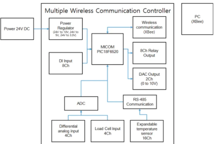
다중 무선통신 컨트롤러는 그림 6과 같이 8개의 블록 으로 설계하였고, MICOM부의 기본 클럭은 16 MHz인 PIC18F6520을 사용하였다. 전원부는 DC 24 V를 입력 받아 DC 10 V, DC 5 V 및 DC 3.3 V를 생성하여 공급 하도록 하였다. 또한, 다이오드를 활용하여 역방향 전 원 투입에 따른 문제점을 고려하였다. 무선통신부는 XBee UART (universal asynchronous receiver transmitter)의 RS-232 통신 표준에 따라 start bit (low), 8 data bits, stop bit(high)로 구성하였고 전송 속도는 9600 bps이다. 디지털 입력부는 포토커플러를 사용하고 디지털 출력부는 달링턴 접속의 드라이버 IC 를 활용하여 그림 7과 같이 회로를 설계하였다.
Fig. 6. Block diagram of multiple wireless communication controller.
그림 8은 완성된 다중 무선통신 컨트롤러의 외형이 다. XBee ID와 그에 따른 컨트롤러 ID를 설정할 수 있 는 딥스위치를 구성하였다.
Fig. 8. The appearance of multiple wireless communication controller.
(a)
(b)
(c) (d)
(e)
(f) (g)
(h)
Fig. 7. Total circuit schematic. (a) MICOM section, (b) power regulator section, (c) wireless communication section, (d) digital input section, (e) digital output section, (f) differential analog &
load cell input section, (g) digital analog converter section, and (h) expandable temperature sensor section.
3. 결과 및 고찰 3.1 RS-232 통신 시험
본 논문에서는 개발한 다중 무선통신 컨트롤러의 데 이터 송수신을 시험하기 위해 그림 9와 같이 UART의 RS-232 통신 표준에 의한 함수를 프로그램하고 GUI (graphical user interface)를 통해 확인하였다.
시험결과 COM포트 3번에서 RS-232 통신 신호가 확 인되었다. 이는 설정 채널에 따른 XBee ID와 다중 무선 통신 컨트롤러가 통신 표준에 따라 정상 작동함을 알 수 있다.
(a)
void CIoTedu1Dlg::OnSendData(BYTE id, BYTE cmd, BYTE data)
{
BYTE send_data[6];
CString str_id, str_data, str;
send_data[0] = (BYTE)0xaa;
send_data[1] = (BYTE)(id);
send_data[2] = (BYTE)(cmd);
send_data[3] = (BYTE)(0xff & data);
send_data[4] = '\0'
m_comm->WriteComm(send_data, 4);
} (b)
Fig. 9. RS-232 communication test of UART. (a) Functions for sending and receiving data and (b) RS232 communication test.
3.2 스타 네트워크 구성 시험
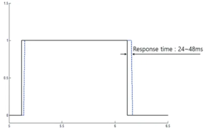
개발된 컨트롤러는 스타 네트워크를 구성하고 그림 10과 같이 XBee ID는 0, 1, 2 그룹, 컨트롤러 ID는 각 그룹마다 설정하였다. 그리고 제어 PC에서 XBee ID 그 룹별로 1 word를 명령하고 high에서 low로 변경되는 시점에 각 1 bit를 10 ms 간격으로 저장하였다.
데이터 분석 결과 그림 11과 같이 24~48 ms의 응답 시간을 확인하였다. 이는 디지털 출력부에서 사용한 릴
Fig. 10. Network configuration test of multiple wireless com- munication controller.
Fig. 11. Controller response time according to input command.
레이의 동작시간 등을 포함한 결과이며, 각 그룹별 컨트 롤러의 데이터 입·출력이 정상 작동함을 알 수 있다.
3.3 다중 무선통신을 활용한 메커니즘 모듈 제어
스마트팩토리 구축을 위한 소규모 제어시스템의 적용 시험을 위해 산업현장의 생산설비에서 사용하는 픽&플 레이스, 캠 리프터, 체인 리프터 메커니즘 모듈을 제작 하였다. 픽&플레이스 메커니즘 모듈은 실린더 조합에 의해 상하 이송, 회전, 그립이 가능하고 캠 리프터와 체 인 리프터 메커니즘 모듈은 모터의 회전운동으로 인한 상하 이송이 가능하다.
픽&플레이스 메커니즘 모듈은 입력신호 6개, 출력신 호 6개, 캠 리프터와 체인 리프터 메카니즘 모듈은 각각 입력신호 7개, 출력신호 2개로 구성되어 있다.
각 메커니즘 모듈은 XBee ID 0, 1, 2 그룹, 컨트롤러
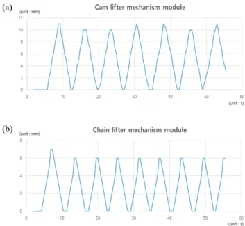
ID는 각 그룹마다 0으로 설정하여 스타 네트워크를 구 성하였다. 그리고 그림 12와 같이 C++을 사용하여 GUI 를 구현하고 그림 13과 같이 제어하였다. 또한, 그림 14 와 같이 캠 리프터와 체인 리프터 메커니즘 모듈의 상하 변위를 0.5s 간격으로 데이터베이스를 생성하고 그래프 로 확인하여 컨트롤러의 유효성을 확인하였다.
Fig. 12. GUI implementation for control and monitoring of mechanism modules.
Fig. 13. Mechanism module control using multiple wireless com- munication controllers.
(a)
(b)
Fig. 14. Lift displacement of cam and chain mechanism module.
(a) Lift displacement of cam lifter mechanism module and (b) lift displacement of chain lifter mechanism module.
4. 결 론
본 논문에서는 스마트팩토리 구축을 위한 소규모 제 어시스템의 다중 무선통신 컨트롤러를 개발하였다. 개발 된 컨트롤러는 스타 네트워크를 구성하여 제어 명령에 따른 출력신호를 10 ms의 간격으로 저장하고 분석한 결과 24~48 ms 내의 응답시간이 발생하였다. 그리고 3 가지의 메커니즘 모듈을 제작하고 네트워크를 구성하여 다중 무선통신으로 제어하였다. 또한, 캠 리프터와 체인 리프터 메커니즘 모듈의 상하 변위를 0.5 s 간격으로 데 이터베이스를 생성하고 모니터링하여 컨트롤러의 유효 성을 확인하였다.
본 논문에서 개발한 다중 무선통신 컨트롤러는 저비 용, UART의 RS-232의 통신 표준으로 인한 다양한 컨 트롤러간의 연계성, XBee 사용과 미들웨어 설계를 통한 1:N의 다중 무선통신 환경 구축, C++ 사용으로 인한 쉬 운 GUI 구현과 데이터베이스 생성이 가능하다.
향후 산업현장 생산설비의 실질적인 적용에 따른 효 과성과 고객 수요에 대한 빅데이터 분석을 연계하여 모 듈 단위의 유연하고 자율제어가 가능한 생산체계 구축 을 위해 지속적인 연구가 필요할 것으로 생각한다.
REFERENCES
[1] J. H. Kwon and S. B. Lee, Koreanische Zeitschrift fuer Wirtschaftswissenschaften, 34, 37 (2016). [DOI: https://doi.org/
10.18237/KDGW.2016.34.3.037]
[2] S. S. Ahn and M. S. Kim, The Magazine of the IEEK, 2016, 2056 (2016).
[3] H. J. Moon, A. Pal, K. C. Kim, and B. S. Ryuh, Journal of the Korean Society for Precision Engineering, 2016, 212 (2016).
[4] S. Y. Kim, I. C. Lim, and S. H. Kim, J. Korean Inst. Intell.
Syst., 26, 195 (2016).
[5] Ying, Shiyan, Zhou, Zeyu, Mei, and Yimin, Journal- Zhejiang University of Technology, 45, 153 (2106).
[6] C. Carmona, B. Alorda, L. Gracia, C. Perez-Vidal, and A.
Salinas, Undersea Hyperb. Med., 44, 243 (2017).
[7] C. Alexandre Gouvea da Silva, E. Leonardo dos Santos, A.
Christian Krainski Ferrari, and H. Tertuliano dos Santos Filho, IEEE America Latina. Revista, 15, 935 (2017).
[8] I. M. Kim, A Study on Sensing System for the Risk Management with XBee, p. 21, Changwon University, Changwon (2012).
[9] I. Y. Jo, Korean J. Air-Cond. Refrig. Eng., 2006, 183 (2006).
[10] S. Y. Lee, J. H. Kim, Y. H. Kim, H. S. Im, M. K. Oh, and Y. S. Hong, Communications of the Korean Institute of Information Scientists and Engineers, 34, 157 (2007).
[11] K. H. Lee, A Study on the Location Estimate using XBee in building, p. 16, Changwon University, Changwon (2015).