1. Introduction 1)
As clean water remains a problem in our current world, improvements in water treatment continue to be researched on. In recent years, membrane separation processes have shown to be a reliable technique for water treatment. This is due to the fact that they have low energy consumption, ease of preparation, and a wide variety of polymers at a relatively low cost. However,
there remains one obstacle that hinders the full potential of the effects of separation membrane, and that is fouling. Fouling removal from membranes has stayed as a formidable challenge to efficient membrane separa- tion processes[1-12]. Reducing fouling has led to con- siderable research on improving membranes by tuning surface chemistry or physical topography. Recently, there has been an increased attention towards surface topography for an improved membrane surface. The
†
Corresponding author(e-mail: [email protected]; http://orcid.org/0000-0002-5858-1747)
헤인 탯 엉
⋅라즈쿠마 파텔 ⋅김 종 학
*
연세대학교 언더우드학부 융합과학공학부 에너지환경융합,**
연세대학교 화공생명공학과(2021년 6월 7일 접수, 2021년 6월 22일 수정, 2021년 6월 24일 채택)
Review on Antifouling Membranes with Surface-Patterning for Water Purification
Hein Htet Aung * , Rajkumar Patel * , Jong Hak Kim **
,†*
Energy and Environmental Science and Engineering (EESE), Integrated Science and Engineering Division (ISED), Underwood International College, Yonsei University, 85 Songdogwahak-ro, Yeonsu-gu, Incheon 03722, South Korea**
Department of Chemical and Biomolecular Engineering, Yonsei University, 50 Yonsei-ro, Seodaemun-gu, Seoul 03722, South Korea(Received Jun 7, 2021, Revised Jun 22, 2021, Accepted Jun 24, 2021)
요 약: 전 세계적으로 물 위기인 상황에서 깨끗한 물에 대한 수요는 꾸준히 이어지고 있다. 이러한 상황에서 정수를 위 한 멤브레인 분리 기술은 중요하다. 멤브레인의 오염 때문에 멤브레인의 분리 효과는 방해되고 있다. 이러한 문제를 해결하기 위해 최근에 여러 방법으로 평막에 패턴을 제공하는 연구와 실험이 수행되었다. 멤브레인의 패턴화는 오염을 줄일 뿐 아니라 방법과 재료에 따라 물투과 유속을 증가시켰다. 각각의 적용된 사례에서 증가된 표면적, 높은 물 투과도, 그리고 향상된 여과 사이클 등과 같은 효과를 보여주었다. 본 총설에서는 오염방지에 대한 패턴화 멤브레인의 효과를 소개하고 논의한다.
Abstract: As clean water continues to be a demand in this global water crisis, development of separation membrane technology for water purification becomes a necessity. The effectiveness of separation membranes is hindered in the water crisis due to fouling of membranes. To address this problem, the application of patterns on flat membranes via various methods have been recently studied and experimented. Patterned membranes have shown to not only reduce the fouling effects of membranes, but also increase the fluxes depending on the method and materials used. Each application has shown benefits that include, but not limited to, enhanced surface area, higher pure-water permeability, and increased number of filtration cycles. In this review, the effects of patterned membranes against antifouling is summarized and discussed.
Keywords: antifouling, patterned membrane, water permeability, filtration
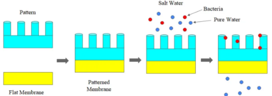
method is to used for patterns on the membrane sur- face that increases surface area. This would show in- creased performance in water permeation and antifoul- ing performances[13-18]. Various methods will be in- troduced, which will show the effectiveness of the pat- terned membranes in separation processes. Yet, while applying patterns on the membranes will show to have many distinct advantages, there will be a possibility of risks being involved such as reduction in BSA re- jection[19-21]. In this review, the various methods of applying pattern membranes and its effectiveness will be summarized. Fig. 1 represents the schematic dia- gram of the antifouling membrane. Table 1 represents the summary of the review.
2. Patterned membrane 2.1. 3D printed membrane
Three main steps were needed to fabricate the 3D printed wavy on the substrates[22]. Autodesk Inventor was employed to control the porous area, pore size and pore structures, followed by applying
an open-access code (link) for designing sinusoidal structures. For the fabrication of wavy and flat mem- branes, they were prepared with 3D wavy substrate, poly (ether sulfone) PES membrane, and a vacuum filtration. Scanning electron microscopy (FESEM) was employed to observe the structures of the membranes.
A contact angle goniometer was also utilized to inves- Fig. 1. Schematic diagram of antifouling membrane
Table 1. Summary of surface-patterned antifouling membrane
Polymer Membrane Fabrication Method Patterning Process Separation Method Water Flux
(LMH) Reference PES Depositing Selective Layer on
a 3D Printed Support Wavy Pattern UF - 22
PES Non Induced Phase Separation Wavy Pattern UF - 23
PES Hydrogel-Facilitated Phase Separation Micro Pattern - - 24
PMMA Hydrogel-Facilitated Phasee Separation Uniform Pattern 1000 25
- Coarse-Grained Molecular Dynamics Surface Pattern Electric Field Direction - 26 PES Thermal Embossing Nanoimprint
Lithography
Sub-Micron
Surface Pattern UF - 27
PA Interfacial Polymerization Micro Pattern UF - 28
PDMS Phase Separation Micromolding Micro Pattern - - 29
PAN Modified Phase Inversion Micro Pattern MF 70 30
PE Interfacial Polymerization Surface Pattern NF 30 31
Poly(ether sulfone): PES; Poly(methyl methacrylate): PMMA; Poly(dimethylsiloxane): PDMS; Polyether: PE; Polyacrylonitrile:
PAN; Poly(vinylidene fluoride): PVDF
hibited 30% greater water permeance compared to the flat membrane. A high oil rejection value (96%) was obtained for both membranes. In terms of fouling per- formance, when a second fouling-cleaning cycle was carried out, it was shown that there was a large differ- ence between the flat and wavy 3D membranes.
For the preparation of the 3D membranes, there were three important: (1) printing of the 3D substrate, (2) preparation of dense layer via phase inversion, and (3) deposition of dense layer on the substrate[23]. The 3D printing of the substrate was designed by the Autodesk Inventor Professional program and the OpenSCAD software. The PES dense and composite membrane were prepared via phase inversion. The morphological properties of the membrane substrate, the dense and 3D composite membranes were charac- terized by FESEM, digital microscope and atomic force microscopy (AFM). Both membranes showed high BSA rejection values (96%). The initial PWP value of wavy membranes was 10% greater than that of flat membrane due to effective filtration area. A high level of PWP was observed after 10 cycles with the water permeance of 65 L/m
2/h/bar.
experiments of hydrogel- facilitated phase separation (HFPS) membranes were carried out. For the dextran rejection, the samples from the permeate and feed sol- utions were compared. Fig. 2 represents the SEM mi- crographs of flat and modified micro patterned surfaces. M1_pristine, M2_untreated and M3_untreated show the membranes from pristine hydrogel mold and the numbers means the order of casting. The pore structure, pore size, water flux and rejection values for these membranes were compared. The pore size calcu- lation results reveal that a drastic decrease from 89 nm for M1_pristine to 54 nm and 51 nm, respectively, for M2_untreated and M3_untreated membranes. The dex- tran rejection value in M2-untreated and M3_untreated membranes were also increased by 1.7 and 2.4 times, respectively, compared to the M1_pristine membrane.
This showed that different membrane performances will be achieved if the hydrogen mold is not treated each time. For preparation of the master molds, the poly(methyl methacrylate) (PMMA) trenches molds were used based on lithography techniques[25]. HFPS membranes were also prepared by a hydrogel solution cast. Porous membranes were also prepared. The sur-
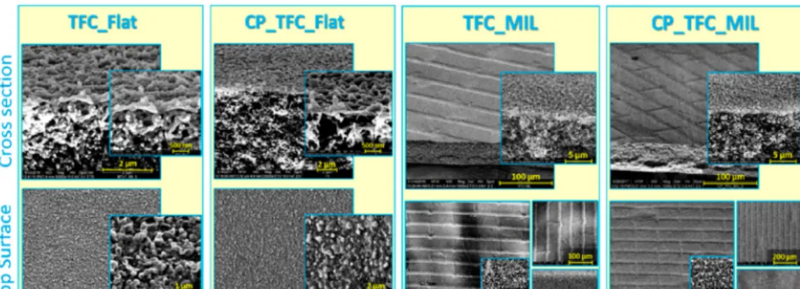
Fig. 2. SEM micrographs of top surface and cross-section morphologies at different magnifications for flat vs. micro-patterned
surface modified (“CP”) and pristine polyamide (PA) thin-film composite (TFC) membranes (Reproduced with permission from Elsherbiny et al., 28).face wettability property was measured by contact an- gle measurement device. HFPS-patterned, HFPS-un- patterned, and NIPS membranes were obtained. The pure water flux values of patterned-hydrogel and the unpatterned-hydrogel membranes was enhanced com- pared to the conventional membrane. Aside from this, the patterned-hydrogel membrane had the increased wa- ter flux relative to the unpatterned-hydrogel membrane.
This was the same case for poly(ethylene glycol) (PEG) rejection. However, HFPS membranes showed near 50% lower rejection compared to the NIPS membrane. The patterned membrane showed a higher initial water flux of around 65% and improved to 78%
increase compared to the unpatterned membrane at the cost of a decrease in BSA rejection of 66% for the patterned and 68% for the unpatterned.
The nanochannel comprised of two opposing solid walls covered with patterned polymer brushes is fab- ricated by the coarse grained molecular dynamics method[26]. The change in the electric field direction resulted in anisotropic transport of the electroosmotic flow (EOF). When the electric field is applied in the direction of stripes, the counterions were aggregated. It was found that a shift of counterion distribution near the interface of brush–fluid phase, and this resulted in reduced friction between the brush and movable coun- terions and thus the arrangement of polymeric chains led to anisotropic electrokinetic transport depending on the electric field directions.
Ding et al. reported two wafer-scale fabrication ap- proach to generate the patterned porous membranes:
phase separation micromolding and a thermal-emboss- ing nanoimprint lithography (NIL) process[27]. This method is based on the phase inversion technique in a patterned mould to fabricate surface-patterned porous films. For the surface patterning of ultrafiltration (UF) and microfiltration (MF) membranes, NIL is used. NIL is a simple and effective technique to generate sub-10 nm features. Using a conventional NIL process, im- printing membranes on the polymer can allow the crea- tion of surface patterns to the features of the mould.
For surfacing patterning of thin-film composite (TFC)
membranes, this was obtained using the barrier layer on interfacial polymerization method on the sur- face-patterned membrane substrate. The article inves- tigated the antifouling effects of the patterned UF membranes.
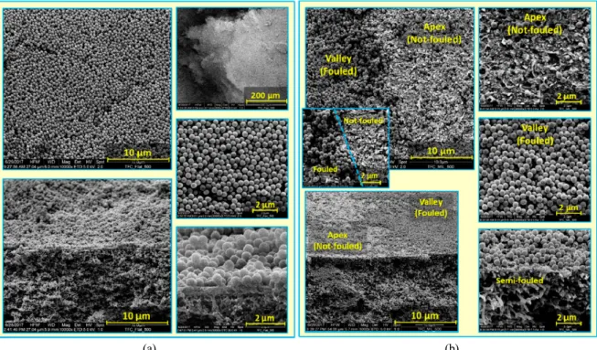
For the preparation of flat isotropic porous PES sub- strate, N-methyl-2-pyrrolidone (NMP) and triethylene glycol (TEG) were added, followed by the introduction of PVP[28]. For the preparation of micro-patterned PES substrates, micro-imprinting lithography and poly (dimethyl siloxane) (PDMS) mold were used to gen- erate a regular pattern comprising an array of straight parallel grooves. Fig. 3 represents the first magnifica- tion view of SEM micrographs for colloidal silica foul- ing effects for the flat and micro-patterned membranes.
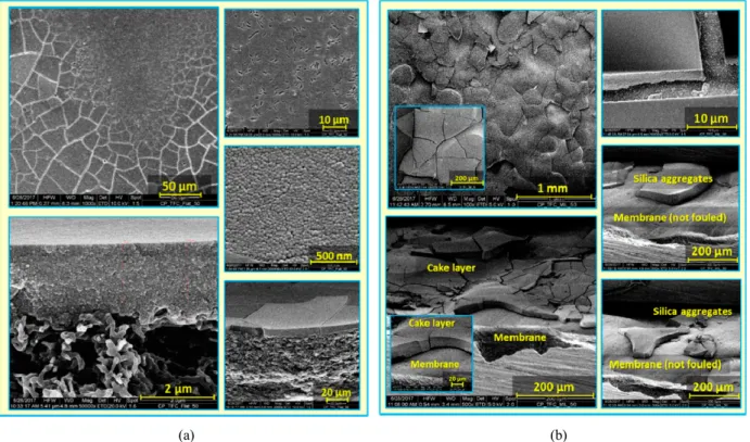
Fig. 4 represents the second magnification view of SEM micrographs for the colloidal silica fouling ef- fects for the flat and micro-patterned surface modified membranes. Fig. 5 represents the third magnification view of SEM micrographs for colloidal silica fouling of flat and micro-patterned surface membranes. The patterned membranes showed noticeably lower flux re- duction compared to their flat counterpart. However, it was found that the surface modified membranes had lower solvent flux compared to their flat counterparts, but had a slightly higher fouling propensity than the pristine membranes. It was observed that the pristine micro-patterned PA TFC membrane had better antifoul- ing propensity compared to the flat pristine TFC mem- brane at 50% reduction in colloidal fouling. d solution.
A general tendency is that flat membranes show a flux decrease while micro-patterned membranes showed limited decline of flux.
The preparation of patterned replica mold was pre-
pared on silicon wafer via photolithography meth-
od[29]. The preparation of patterned poly(vinylidene
fluoride) (PVDF) substrates were prepared using two
different PVDF layers on the non-woven fabric via
phase inversion micromolding. The non-patterned
PVDF substrate membrane was fabricated using the
conventional phase inversion immersion precipitation
method. For preparation of patterned PDMS mem-
(a) (b)
Fig. 3. SEM micrographs at different magnifications for colloidal silica fouling of flat (a) and micro-patterned (b) pristine PA
TFC membranes using silica microparticles (500 nm) in unstirred dead-end filtration conditions (Reproduced with permission from Elsherbiny et al., 28).(a) (b)
Fig. 4. SEM micrographs at different magnifications for colloidal silica fouling of flat (a) and micro-patterned (b) pristine PA
TFC membranes using silica nanoparticles (50 nm) in unstirred dead-end filtration conditions (Reproduced with permission from Elsherbiny et al., 28).branes, patterned and non-patterned PVDF substrates were completely dried before casting the PDMS se- lective layer. For the characterization, the pore-size dis- tribution of membranes was determined by capillary flow porometry. This resulted in surface patterned non- porous PDMS composite membranes with higher etha- nol recovery efficiency and a two-layer printed PVDF substrate. Results showed for crosslinked membranes by TEOS, the pattern size was greater than that of p-TTES. The increase of total flux caused by higher pattern size, but also endued it with superior permeability. This result is completely inverted from non-patterned p-TTES displaying a higher total flux to non-patterned TEOS. Patterned TEOS also showed promise when total flux at very low concentration was significantly enhanced by surface patterning.
Ilyas et al. reported the preparation of casting knives were created using AutoCAD 2018[30]. For the syn- thesis and characterization, poly(acrylonitrile) (PAN)
casting solutions were prepared using dimethyl sulf- oxide (DMSO) as the solvent. The flat non-sprayed membranes were fabricated by the conventional NIPS.
For the synthesis of patterned membranes, the pat- terned doctor blade was directly attached to the sprayed non-solvent induced phase separation (s-NIPS) method. The mean flow pore size and pore size dis- tribution were calculated by a gas–liquid displacement based porosimeter. Using the high throughput dead-end filtration, the clean water permeates (CWP) of the membranes were determined. For the measurement of cross-flow filtration, the effect of patterned surface was examined by the cross-flow microfiltration of BSA solution. 3D numerical simulation was performed for steady-state Navier-Stokes flow using COMSOL. The flat-sprayed membrane (F
S) resulted in 53% (347 L/m
2/h/bar) increase in CWP. The Rec
500, Tri
500and Cir
500membranes also indicate substantial enhancement in CWP compared to the flat non-sprayed membrane.
(a) (b)