http://dx.doi.org/10.7848/ksgpc.2015.33.6.557
Accuracy Comparison Between Image-based 3D Reconstruction Technique and Terrestrial LiDAR for As-built BIM of Outdoor
Structures
Lee, Jisang1)ㆍHong, Seunghwan2)ㆍCho, Hanjin3)ㆍPark, Ilsuk4) Cho, Hyoungsig5)ㆍSohn, Hong-Gyoo6)
Abstract
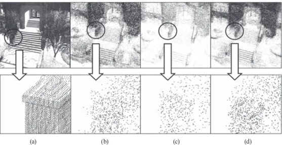
With the increasing demands of 3D spatial information in urban environment, the importance of point clouds generation techniques have been increased. In particular, for as-built BIM, the point clouds with the high accuracy and density is required to describe the detail information of building components. Since the terrestrial LiDAR has high performance in terms of accuracy and point density, it has been widely used for as- built 3D modelling. However, the high cost of devices is obstacle for general uses, and the image-based 3D reconstruction technique is being a new attraction as an alternative solution. This paper compares the image- based 3D reconstruction technique and the terrestrial LiDAR in point of establishing the as-built BIM of outdoor structures. The point clouds generated from the image-based 3D reconstruction technique could roughly present the 3D shape of a building, but could not precisely express detail information, such as windows, doors and a roof of building. There were 13.2~28.9 cm of RMSE between the terrestrial LiDAR scanning data and the point clouds, which generated from smartphone and DSLR camera images. In conclusion, the results demonstrate that the image-based 3D reconstruction can be used in drawing building footprint and wireframe, and the terrestrial LiDAR is suitable for detail 3D outdoor modeling.
Keywords : Terrestrial LiDAR, Image-based 3D Reconstruction, Building Information Modelling (BIM), point clouds, Structure from Motion (SfM)
557 Original article
Received 2015. 11. 30, Revised 2015. 12. 24, Accepted 2015. 12. 31
1) School of Civil and Environmental Engineering, Yonsei University, Seoul 03722, Korea (E-mail: [email protected]) 2) Member, School of Civil and Environmental Engineering, Yonsei University, Seoul 03722, Korea (E-mail: [email protected]) 3) School of Civil and Environmental Engineering, Yonsei University, Seoul 03722, Korea (E-mail: [email protected]) 4) School of Civil and Environmental Engineering, Yonsei University, Seoul 03722, Korea (E-mail: [email protected]) 5) Member, School of Civil and Environmental Engineering, Yonsei University, Seoul 03722, Korea (E-mail: [email protected])
6) Corresponding Author, Member, School of Civil and Environmental Engineering, Yonsei University, Seoul 03722, Korea (E-mail: [email protected])
This is an Open Access article distributed under the terms of the Creative Commons Attribution Non-Commercial License (http://
creativecommons.org/licenses/by-nc/3.0) which permits unrestricted non-commercial use, distribution, and reproduction in any medium, provided the original work is properly cited.
1. Introduction
Recently, 3D spatial information is becoming necessary in various fields, such as robotics, disaster management, and Information and Communication Technology (ICT). Moreover, those developments in smartphones and telecommunication environments have accelerated the utilization of 3D spatial information. In particular,
there are increasing demands for accurate and precise construction of 3D spatial information in the Building Information Modelling (BIM) field in order to measure, inspect, and verify the safety of structures (Randall, 2011;
Isikdag et al., 2013). However, the acquisition of accurate and precise 3D spatial data is a laborious and costly task.
For the reason, researchers currently perform studies in developing more efficient techniques in cost and time.
558
Those acquisition methods for 3D data can be classified into two major categories; one is the range-based technique using a Light Detecting and Ranging (LiDAR), while the other is image-based 3D reconstruction techniques based on the principle of the photogrammetry and computer vision (Tang et al., 2010; Klein et al., 2012). The terrestrial LiDAR collects the 3D data of target objects by bouncing light off from the object and contours an image on the basis of light-return rates and angles. The terrestrial LiDAR has been verified as the most superior solution for 3D data acquisition in terms of getting accurate and dense point data in relatively short time (Jazayeri et al., 2014;
Cho et al., 2015). The terrestrial LiDAR has been utilized to acquire accurate 3D point clouds data in various fields, such as construction management (Su et al., 2006), forest science (Dassot et al., 2011), landslide monitoring (Jones, 2006), and snow depth measurement (Prokop, 2008). The point clouds observed by terrestrial LiDAR have been specifically applied in the field of BIM to improve the efficiency for facility management of indoor and outdoor environments (Tang et al., 2010; Jung et al., 2014; Hong et al., 2015). Randall (2011) conceptually proposed standards for building information modelling based on point clouds, gathered from the LiDAR. According to the propose, the point clouds for structural analysis and inspection needs 1cm of accuracy, while it needs 1m of accuracy for rapid urban modelling. However, in the study, an actual test had not been conducted, whereas there was also no well-defined evaluation standard yet for evaluating the performance of 3D BIM construction.
Despite of its accuracy and productivity, the terrestrial LiDAR device accompanies a financially big concern for general uses due to its expensive costs, more than a hundred thousand dollars. An alternative solution to reduce the cost of point clouds acquisition is the image-based 3D reconstruction techniques, which have been already applied in some commercial fields via image big data collected from the internet (Snavely et al., 2007; Uricchio, 2011). The Image-based 3D reconstruction techniques, which can be conducted automatically with a relatively low cost, have been studied for various applications, such as construction sites (Golparvar-Fard et al., 2011), facility
management (Bhatla et al., 2012), and archaeology (Brutto and Meli, 2012; Kersten and Lindstaedt, 2012; De Reu et al., 2013).
However, when using multiple image data from uncertain sources, the quality of final products could be negatively affected by the inconsistency in captured date, weather conditions, resolution, as well as the ambiguity of image geometry. Due to the qualitative uncertainty of 3D point clouds generated from multiple sources, a qualitative analysis evaluating the performance of the image-based 3D reconstruction techniques has been conducted. In fact, the results were cross analyzed with the observed data from traditional measuring method (Dai and Lu, 2010) and terrestrial LiDAR data (Dai et al., 2013). In addition, Bhatla (2012) conducted the image-based as- built 3D modeling of bridge, which compared with the 3D model generated from 2D drawings, and Yang et al.
(2013) applied the image-based 3D reconstruction to an augmented reality technique.
Previous studies had verified the performance of image-based 3D reconstruction technique for various applications. For as-built BIM, accuracy and point density of a point clouds must be achieved in centimeter level to express the detail geometric information of building structures. Since the distance between target and camera sensor was not close in outdoor observation, those point clouds from multiple images cannot ensure their point density and accuracy without special platforms, such as an unmanned areal vehicle (UAV) (Dai et al., 2013).
In this regard, this paper has conducted the evaluation of image-based 3D reconstruction technique and terrestrial LiDAR, in terms of establishing as-built BIM of outdoor structures. Also, their performances were compared with respect to noise ratio, point density, and accuracy. Images for generating a point clouds were collected by smartphone camera and Digital Single-Lens Reflex (DSLR) camera, which can be easily used by general users with the low cost. A terrestrial LiDAR device of pulsed type, which is widely used for outdoor observation, was selected. For the comparison analysis, the coordinate system of point clouds from multiple images was converted into the coordinate system of the LiDAR data, using 3D conformal
559 transformation and Iterative Closest Point (ICP) algorithm.
For the accuracy comparison, those checking points were extracted by the RANdom SAmple Consensus (RANSAC) algorithm.
2. Methodology
In the paper, the image-based 3D reconstruction method and the terrestrial LiDAR scannning for 3D modelling of outdoor building were conducted independently and compared in terms of the point density and accuracy. The overall process is summarized in Fig. 1.
2.1 Test site and device
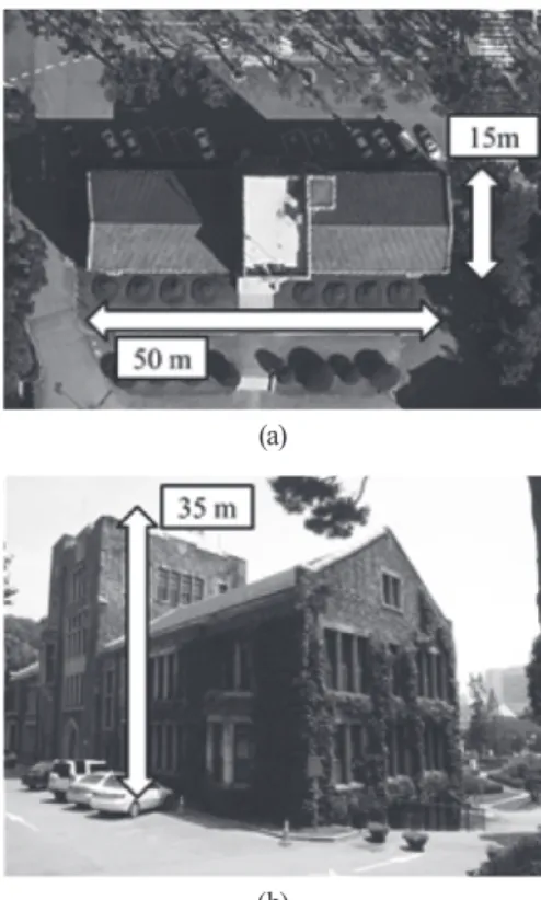
In comparing the image-based 3D reconstruction technique and the terrestrial LiDAR scanning for outdoor modelling, the outdoor building image of size is 50 m x 15 m x 35 m was selected. The test building presents in the Fig.2, including front door with stair, windows, roof, and many other building components, which are generally considered as structures in outdoor building modelling.
The Leica ScanStation 2 was used for the LiDAR scanning and its specification was summarized in Table 1 (Leica Geosystems, 2007). As shown in Table 1, the Leica ScanStation 2, which is the pulsed type scanner, has an
effective range of 300 m and positioning accuracy of 6 mm.
A smartphone camera and a DSLR camera were used
Fig. 1. Flowchart of overall process
Fig. 2. Test site for 3D outdoor modelling: (a) top view, and (b) side view
(a)
(b)
Table 1. Specification of Leica Scanstation 2
Type Pulsed
Range 300m@90%,
134m@18% albedo Scan rate Up to 50,000 points/sec Accuracy of
single measurement*
Position* 6mm
Distance* 4mm
Angle 60µrad
Field of view Horizontal 360° (maximum) Vertical 270° (maximum)
Weight 18.5 kg
Size (depth, width, height) 265, 370, 510 mm
Camera Integrated high-
resolution digital camera
* At 1 m~50 m range, one sigma
560
to evaluate the performance of the image-based 3D reconstruction technique. The Table 2 shows the specification of the smartphone and the DSLR camera, which are used in the experiments. As shown in Table 2, the spatial resolutions of the smartphone images were lower than those of the DSLR images.
2.2 Terrestrial LiDAR scanning
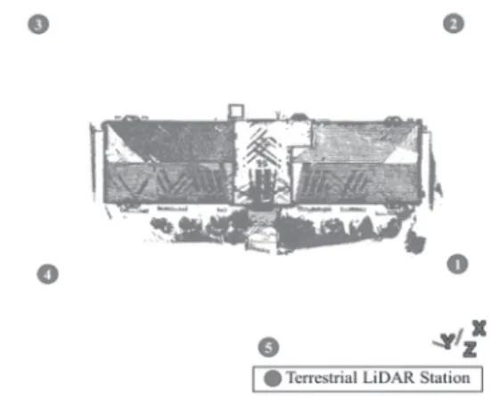
Since the single-scanned data cannot cover every side of the building, the multiple scanning process and registration process to convert the relative coordinate systems of the multi-scanned data to a common coordinate system are required. The registration can be classified into the target-free method and the target-based method. The target-free method based on the ICP algorithm can automatically perform the registration, but the accuracy cannot be guaranteed. Thus, the target-based method using artifacts, such as sphere, paddle, and paper targets and natural point features is generally applied for as-built BIM due to its accuracy and efficiency. In this study, natural point features in overlapped areas were manually extracted and used for the target-based registration. In addition, target-free method was applied to improve precision of registration.
A model for the registration of point clouds with an absolute scale factor can be conducted on the basis of 3D rigid body
transformation, which includes a rotation matrix (
cos sin sin cos
cos sin sin cos
cos sin sin cos
≥ ),and translation vector (
cos sin sin cos
cos sin sin cos
cos sin sin cos
≥
). The model equation can be represented by Eq. (1):
(1)
cos sin sin cos
cos sin sin cos
cos sin sin cos
≥ where
cos sin sin cos
cos sin sin cos
cos sin sin cos
≥ ,
cos sin sin cos
cos sin sin cos
cos sin sin cos
≥ and
cos sin sin cos
cos sin sin cos
cos sin sin cos
≥
are the 3D coordinates of the converted points,
cos sin sin cos
cos sin sin cos
cos sin sin cos
≥ ,
cos sin sin cos
cos sin sin cos
cos sin sin cos
≥
and
cos sin sin cos
cos sin sin cos
cos sin sin cos
≥
are the original 3D coordinates of the observed points, and is the rotation matrix.
This can be calculated as follows:
cos sin sin cos
cos sin sin cos
cos sin sin cos
≥
(2)
cos sin sin cos
cos sin sin cos
cos sin sin cos
≥
where,
cos sin sin cos
cos sin sin cos
cos sin sin cos
≥ ,
cos sin sin cos
cos sin sin cos
cos sin sin cos
≥ and
cos sin sin cos
cos sin sin cos
cos sin sin cos
≥
are the rotation angles about X-axis, Y-axis, and Z-axis, respectively.
The 3D rigid body transformation requires at least two matching points to estimate the six transformation parameters. However, it is difficult to extract the accurate 3D coordinates of common point features in overlapped point clouds. To overcome the locational ambiguity of matching points, the ICP algorithm can be additionally applied for a robust registration. The ICP algorithm iteratively finds the closest points in a pair of point clouds and automatically estimates transformation parameters for the minimization of locational inconsistency between a pair of point clouds (Besl and McKay, 1992). After the target-based registration using the point features is conducted, the ICP algorithm can be additionally conducted to improve precision of the aligned point clouds.
2.3 Image-based 3D reconstruction
The Structure-from-Motion (SfM) technique-based on the integration of the principle of photogrammetry and computer vision- is known as the most practical solution to generate a point cloud from hundreds or thousands of images of which camera parameters and orientations are unknown (Golparvar-Fard et al., 2011; Brutto and Meli, 2012). Since the interior orientation parameters of a focal length and lens distortion are estimated relatively in the SfM process, the process for estimating camera parameters distortions can be omitted (Golparvar-Fard et al., 2011).
The flowchart of image-based 3D reconstruction is Table 2. Specification of the utilized smartphone and
DSLR cameras Specification Smartphone
camera DSLR camera
Model Samsung
Galaxy S II Canon EOS Rebel T3i
Sensor type CMOS CMOS
Sensor format 1/3.2″ APS-C
Sensor size 4.54mm × 3.42mm 22.30mm × 14.90mm
Pixel Pitch 1.39 μm 4.30 μm
Focus mode Autofocus Autofocus
Image size 3264 × 2448 5184 × 3456
Focal length 4 mm 17 mm