http://doi.org/10.14347/kadt.2017.39.1.35
CAD/CAM 밀링 시스템을 활용한 단일 치관과 3본 교의치의 3D 적합도 평가
김소리, 김총명*, 김웅철, 김지환
고려대학교 대학원 보건과학과 치의기공전공, 고려대학교 보건과학연구소
*Three-dimensional evaluation of the internal adaptation of single and three- unit fixed dental restoration by CAD/CAM milling system
So-Ri Kim, Chong-Myeong Kim*, Woong-Chul Kim, Ji-Hwan Kim
Department of Dental Laboratory Science & Engineering, College of Health Science, Korea University*
Institute for Health Science, College of Public Health Science, Korea University
[Abstract]
Purpose: The purpose of this paper was to evaluate the occurrence of errors regarding adaptation by conducting a three-dimensional assessment comparing the bridge type dental restoration after the cutting process, which has multiple abutments, with a single type dental restoration.
Methods: By using ten identical files obtained by scanning the master model, thirty designs were created consisting of ten maxillary right first premolars and ten maxillary right first molars with single crown abutments, along with ten bridge designs with the identical abutment. A 5-axis milling machine was used to produce the design file. The produced denture prostheses were scanned using a silicone replica for a STL file. An evaluation was conducted using 3D analysis software on the master model and each of the thirty data files.
Results: The RMS value of the pre-molar (14) was 38.4 ± 4 µm for single and 54.7 ± 6 µm for bridge abutment;
therefore, a statistically significant difference was observed for single and bridge designs although both shared the same abutment form (P<.05). Also, the RMS value of the molar (16) was 47.6 ± 2 µm and 56.6 ± 5 µm for the single and bridge designs, respectively, thereby presenting a statistically significant difference (P<.05).
Conclusion: As a result, dental prosthesis fabricated using the single method presented better internal adaptation outcomes.
Key words: CAD/CAM system; Milling system; Three-dimensional evaluation; Gap; Three-unit fixed dental restorations
교신저자 성 명 김 지 환 전 화 010-6270-0341 E-mail [email protected]
주 소 서울시 성북구 안암로 145 고려대학교 보건과학대학 치기공학과
접 수 일 2016. 10. 31 수 정 일 2017. 3. 2 확 정 일 2017. 3. 13
Ⅰ. 서 론
캐드캠 (Computer-aided design / Computer- aided manufacture) 시스템은 수십 년 동안 많은 산 업 분야에서 중요한 부분으로 이용되어 왔다. 특히 복잡 한 형상을 제작하는 산업분야에서 주로 사용 되고 있으 며 (Tinschert at al, 2004; Ng at al, 2014), 최근에는 기술이 더욱 개선되어 치과분야에 적용되기 시작했다 (Beuer at al, 2008).
치과분야에 도입되어 사용되고 있는 캐드캠 시스템 은 모델의 3차원 스캔과 보철물의 설계, 그리고 가공으 로 나눌 수 있다 (Tinschert at al, 2001). 3차원 스캔은 환자의 구강이나 모형을 스캐너로 스캔하여 디지털 데 이터로 변환시키는 과정이고, 보철물의 설계는 캐드 프 로그램으로 보철물을 환자에 맞게 디자인하는 과정, 그 리고 가공은 디자인된 데이터를 보철물에 알맞은 재료 로 제작하는 과정으로 구분할 수 있다 (Rekow, 1987;
Samet at al, 1995; Beuer at al, 2008; Vafiadis &
Goldstein, 2011).
기존의 연구들에서는 절삭 가공 장비 (Milling system)로 제작 된 고정성 보철물이 임상에서 허용 가능한 범위에 있다고 제시한 바가 있다 (Kim et al, 2014; Kim at al, 2015; Pradies at al, 2015). 하지만 단일 치관이나 단일 코핑과 같은 하나의 지대치를 가지 고 연구한 경우가 대부분이고 (Anadioti at al, 2014;
Kim at al, 2014; Pradies at al, 2015; Kim at al, 2015), 여러 개의 지대치를 가지고 있는 교의치 형태의 보철물을 단일 형태의 보철물과 적합도를 비교한 연구 는 부족한 실정이다. 또한 단일 치관 보철물과는 다르게 3본 교의치 형태의 크라운 보철물은 절삭하는 공구의 각도가 보철물의 형태나 지대치 축 방향에 따라서 절삭 각도와 밀링 과정 등이 달라지기 때문에 내면의 적합도 에 영향을 미칠 수 있다 (Kim at al, 2003). 하지만 이 러한 차이를 명확하게 조사한 연구도 많이 부족한 실정 이다.
단일 치관 보철물과 지대치와의 오차를 평가하기 위해 서는 주로 마진 적합도와 내면 적합도를 직접 확인하는 방법이 사용 되어왔다 (Park at al, 2015; Pradies at
인 형태를 평가하기에는 한계가 있다. 이러한 단점을 보 안 하기 위해 3차원 방법을 통하여 평가한다면 어느 부 분에 얼마나 오차가 있는지 시각적으로 평가할 수 있을 뿐만 아니라 최종 보철물을 임상적으로 적용하기 앞서 수정도 가능하다 (Tinschert at al, 2001; Shah at al, 2004).
따라서 본 연구의 목적은 캐드캠 밀링 시스템으로 제 작 된 단일 치관과 3본 교의치 고정성 보철물의 내면적 합도를 3차원으로 평가하고자 한다.
Ⅱ. 연구 방법 1. 지대치 제작
본 연구에 사용된 모델은 상악 우측 제1 소구치와 상 악 우측 제1 대구치가 있고 상악 우측 제2 소구치가 없는 형태의 모형 (Model #3017, Viade products, California, U.S.A)을 선택하였다.
지대치 형성 (preparation)은 1.5mm로 교합면을 삭제하고, 1.2mm로 360°의 chamfer margin을 형 성한 후, 5°의 축벽 각도를 주어서 제작하였다. 주 모 형을 제작하기 위해서 아크릴 지대치로 10개의 실 리콘 (Dublisil, Dreve Dentamid GmbH, Unna, Germay) 몰드를 제작하였고, 에폭시 (Modralit ® 3K, DentamidDreve, Unna, Germany)를 실리콘 몰드에 주입하여서 최종적으로 10개의 주모형을 제작하였다.
2. 스캔 및 밀링
1 0 개 의 주 모 형 은 치 과 용 블 루 라 이 트 스 캐 너
(Identica ® BLUE, Medit, Seoul, Korea)로 스캔 하였
다. 스캔 된 지대치 파일로 단일 치관과 3본 교의치 고
정성 보철물을 제작하기 위해 주모형에서 스캔하여 얻
어진 10개의 동일 한 파일을 이용하여 상악 우측 제1 소
구치, 상악 우측 제1 대구치의 단일 치관을 디자인하였
다. 그리고, 같은 스캔 파일을 이용하여 상악 우측 제
1 소구치와 상악 우측 제1 대구치가 지대치로 되어 있 는 교의치 형태의 3본 교의치 고정성 보철물 디자인 하 였다. 디자인은 치과용 CAD 프로그램 (Dent CAD,
Delcamplc., Birmingham, UK)으로 디자인하였고, 크라운 디자인을 동일하게 제작하기 위해서 수정을 하 지 않고 프로그램 내에 저장되어 있는 형태를 그대로 사
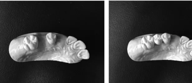
Figure 1. Single and three-unit fixed model.
Figure 2. Schematic design of study workflow chart
GO2cam International, Terreaux, Lyon, France)으 로 공구 가공 경로를 생성하였다. 공구 가공 경로의 생 성이 완료 되면 각각 NC 파일로 저장하여 5축 밀링 장 비 (DWX-50, Roland DG Corporation, Shizuoka, Japan)에 적용 시켜 상악 우측 제1 소구치, 상악 우 측 제1 대구치 단일 치관을 각각 10개씩, 3본 교의 치 크라운 10개를 밀링 하였다 (Fig. 1),(Fig. 2). 크라 운 제작에 사용된 블럭은 PMMA 재료 중의 하나인 우 레탄 블록 (innoBlanc ®model, innoBlanc GmbH, Gewerbepark, Engelsbrand)을 사용하였다.
3. 3차원 측정
밀링된 보철물은 실리콘 인상재 (Aquasil Ultra XLV, Dentsply DeTrey GmbH)를 보철물 내면에 주입한 후 주모형 지대치에 적합시켰다. 10분동안 50N의 동일 한 힘으로 실리콘이 완전히 중합 될 때까지 압축장비 로 압축 시켰다. 완전히 중합 된 후 보철물을 제거하고 지대치 위에 있는 실리콘의 얇은 막을 치과용 블루 라 이트 스캐너로 스캔하여서 STL 파일을 얻었다. 보철
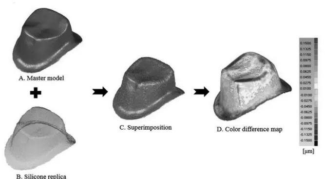
(Geomagic Verify 2015; Geomagic GmbH, Leipzig, Germany)를 사용하여 측정하였다. 주모형과 각각 실 리콘 스캔 데이터를 Auto Alignment로 배열을 한 후, Align Best Fit을 통해 다시 한번 배열을 해주었다. 그 리고 Whole Deviation을 통해 color-map으로 나타 내었다 (fig. 3). 중첩을 통하여 얻은 적합도의 차이는 root mean square (RMS)값으로 표현하였다.
4. 통계분석
주모형과 단일 치관과 3본 교의치 스캔데이터를 각각 RMS값, 표준편차, 95% CI 등의 통계량을 제시하였다.
정확한 검증을 위하여 먼저 Levene test를 통하여 그룹 간의 분산이 같다고 가정할 수 있었다. t-test를 시행하 고 측정 오차를 산출하였으며, 통계적 유의수준은 0.05 로 하였다. 측정된 결과들은 통계적 유의성을 검증하 기 위하여 통계 프로그램 (SPSS Statistics 20.0, IBM, Chicago, IL, USA)를 이용하여 분석하였다.
Figure 3. Three-dimensional measurement for internal gap. A, Master model: scanning epoxy model with dental scanner;
B, Silicon replica: point cloud data from digital replica; C, Superimposition: master model data and digital silicone
replica data was measured by superimposing the two; D, Color difference map.
Ⅲ. 결 과
Table 1에서 소구치의 RMS의 값은 단일 치관일 때, 38.4±4 µm이고, 3본 교의치일때 54.7±6 µm으 로 같은 지대치의 형태를 가지고 있더라도 단일치관 과 3본 교의치일 때 통계적으로 유의한 차이를 보였다 (p<0.05). 대구치의 RMS의 값은 단일 치관일 때 47.6
±2 µm이고, 3본 교의치일 때 56.6±5 µm으로 같은 지대치의 형태를 가지고 있더라도 단일 치관과 3본 교
의치일 때 통계적으로 유의한 차이를 보였다(p<0.05).
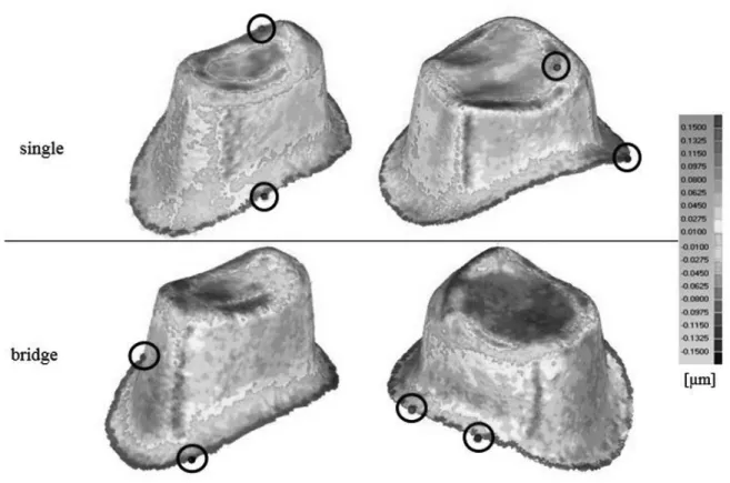
Color-difference map에서는 단일치관과 3본 교의 치를 비교하면 소구치와 대구치 모두 동일하게 3본 교 의치가 단일치관에 비해 양의 오차와 음의 오차가 더 진 하고 넓게 펴져있는 것을 확인 할 수 있기 때문에 오차 가 더 크다는 것을 확인 할 수 있다. 빨간점은 가장 많이 차이 나는 한 점을 표시한 것이고, 파란점은 가장 적게 차이 나는 한 점을 표시한 것이다. 대부분 변연 부위에 서 파란점을 볼 수 있으므로 변연 쪽이 가장 적합이 좋
Table 1. RMS(µm) of three-dimensional gaps associated with single and three-unit fixed dental fabricated with CAD/CAM milling system
RMS, root mean square ; CI, confidence interval
*Statistically significant difference (p< 0.05).
Three-dimensional evaluation of internal Gap (µm)
Single Bridge
RMS±SD 95% CI RMS±SD 95% CI
Pre-molar(14) 38.4±4 34.9–42.0 54.7±6* 50.1–59.3
Molar(16) 47.6±2 45.7–49.5 56.6±5* 52.3–60.9