Vol.18, No.1, (2016), pp.50~54 http://dx.doi.org/10.9714/psac.2016.18.1.050
Hybrid design method for air-core solenoid with axial homogeneity
Li Huanga, Sangjin Lee*,a, and Sukjin Choib
a Uiduk University, Gyeongju, Republic of Korea
b Institute for Basic Science, Republic of Korea
(Received 29 January 2016; revised or reviewed 22 March 2016; accepted 23 March 2016)
Abstract
In this paper, a hybrid method is proposed to design an air-core superconducting solenoid system for 6 T axial uniform magnetic field using Niobium Titanium (NbTi) superconducting wire. In order to minimize the volume of conductor, the hybrid optimization method including a linear programming and a nonlinear programming was adopted. The feasible space of solenoid is divided by several grids and the magnetic field at target point is approximated by the sum of magnetic field generated by an ideal current loop at the center of each grid. Using the linear programming, a global optimal current distribution in the feasible space can be indicated by non-zero current grids. Furthermore the clusters of the non-zero current grids also give the information of probable solenoids in the feasible space, such as the number, the shape, and so on. Applying these probable solenoids as the initial model, the final practical configuration of solenoids with integer layers can be obtained by the nonlinear programming. The design result illustrates the efficiency and the flexibility of the hybrid method. And this method can also be used for the magnet design which is required the high homogeneity within several ppm (parts per million).
Keywords: air-core solenoid, axial uniformity, hybrid method, linear programming, nonlinear programming
1. INTRODUCTION
Many methods have been used in the solenoid design.
The classical approach is to specify the dimension of solenoid with the maximum Fabry factor [1]. However, it is not suitable to deal with the complex constraints of the practical design. Other methods such as Genetic Algorithm can involve the nonlinear problem and have the obvious advantage at the engineering design [2]. The requirements of design can be easily described as nonlinear inequality or equality constraints, and it enhances the flexibility and readability of optimization problem. The nonlinear optimization methods are powerful but relatively slow. There is often no guarantee that the computed solution is the most optimal. Recently, several methods using the linear optimization have been applied to solve the solenoid design problem [3]. These methods are very efficient and can get an optimal solution theoretically. Whereas the rounding layers and turns of winding are considered, the constraints of optimization may be violated seriously.
In this paper, a hybrid optimization method was presented to design a 6 T solenoid magnet to generate a uniform magnetic field of 0.4% within 600 mm along z- axis. The solenoid can be used in an electron beam ion source (EBIS) to compress the electron beam from an electron gun [4]. The hybrid optimization method is composed of a linear programming and a nonlinear programming [5]. The linear programming is employed to obtain a global optimal current distribution in a feasible space of solenoid. And the nonlinear programming is used to improve the current distribution
to satisfy the requirement of design and revise its size to practical solenoids with rectangular cross-section. The process of hybrid optimization method was described in section 2. Using the hybrid optimization method, the design result of superconducting solenoid magnet was presented in section 3.
2. OPTIMIZATION METHOD 2.1. Process of optimization method
The purpose of design in this paper is to obtain a minimum volume electromagnet, which can generate uniform magnetic field on a straight line. Air-core solenoid is used in the design. And the whole process of the hybrid optimization method can be divided into three stages:
A. Analysis stage:
Solenoids in the design are located in a cylindrical coordinates (𝜌, 𝜑, 𝑧) and symmetric about the z-axis.
For the sake of convenience, it is assumed that the current density is uniform across the cross-section of solenoid. The designed magnetic field at center point is 𝐵0, and the uniformity is better than 𝜀 within a certain range 𝐿𝑚𝑎𝑥 on the z-axis.
Beside the constraints of the magnetic field at center point and the uniformity, the sizes of solenoids are restricted by the bobbins, the gap, and other equations.
When the superconducting wire is used in solenoid design, the critical current depending on the maximum magnetic field also should be considered in the design.
*Corresponding author: [email protected]
B. Linear programming stage
The feasible space of solenoids is divided into many grid elements. The magnetic field generated by each grid element can be approximated to the field generated by an ideal current loop which is located at the center of grid.
Using the linear programming, a global optimal current distribution in several grid elements can be obtained. The clusters of non-zero current grids can indicate the number and size of solenoids.
C. Nonlinear programming stage
The result of linear programming provides an initial point for the nonlinear programming. Using the nonlinear programming, all clusters of non-zero current grids are revised into practical solenoids with rectangular cross- section.
2.2. Linear programming
Assume the inner radius of solenoid should be greater than 𝜌𝑚𝑖𝑛 and the outer radius should be less than 𝜌𝑚𝑎𝑥, the height of solenoid should be less than 2𝑍𝑚𝑎𝑥. Considering in the design, the solenoid is symmetric about the plane 𝑧 = 0 , only 1/2 feasible space is calculated in the optimization as shown in Fig. 1.
The feasible space is divided into 𝑀𝑠× 𝑁𝑠 grid elements, which 𝑀𝑠, 𝑁𝑠 are the number of segments on the radial direction and the axial direction, respectively.
Each grid element represents an ideal current loop 𝐼𝑖 which is located at center point (𝜌𝑖, 𝑧𝑖) of the grid element.
The design variables for linear programming are the current flowing through each grid, [𝐼1, 𝐼2, ⋯ , 𝐼𝑀𝑠×𝑁𝑠].
The maximum current 𝐼𝑚𝑎𝑥 in each grid can be calculated by
s max s
min max
max N
z J M
I
(1)
where, 𝐽 is the current density in each grid.
For the simplification, the design variables are normalized by 𝐼𝑚𝑎𝑥 and became [𝑒1, 𝑒2, ⋯ , 𝑒𝑀𝑠×𝑁𝑠],
Fig. 1. Half of feasible space of solenoids and current grid elements.
where 𝑒𝑖=𝐼𝐼𝑖
𝑚𝑎𝑥, 𝑖 = 1,2, ⋯ , 𝑀𝑠× 𝑁𝑠. Then all design variables are between 0 and 1.
The objective function is the volume of solenoids, and it can be calculated by
MsNs
i i i
max e
J Vol I
1
2 (2)
where 𝐼𝑚𝑎𝑥 is the maximum current in each grid, 𝐽 is the current density, 𝜌𝑖 is the radius of the center point of 𝑖th grid, and 𝑒𝑖 is the normalized current in 𝑖th grid.
Considering the axial component of magnetic field is much larger than the radial component in the solenoid, the uniformity of magnetic field can be verified by the 𝐵𝑧 component of magnetic field at 𝑁𝑡 target points in the specific range on the z-axis. According to the Biot- Savart law, the magnetic flux density at target point (𝜌𝑗, 𝑧𝑗) generated by the ideal current loop 𝐼𝑖 can be calculated by
()
) ( ) (
) ) (
( ) ( ) (
1 ) 2
,
( 2 2
2 2
2 2
2
0 Ek
z z
z k z
K z z z I
B
i j i j
i j i j i
j j i i j j
z
(3)
() ()
) ( ) (
) ( )
( ) 2 (
) ,
( 2 2
2 2 2 2 2
0 Ek Kk
z z
z z z
z z I z
z B
i j i j
i j i j i j j i j
i i j
j
j
(4)
where 𝜌𝑖 and 𝑧𝑖 are the coordinates of 𝑖th ideal current loop, 𝜌𝑗 and 𝑧𝑗 are the coordinates of 𝑗th target point, the function 𝐾 and 𝐸 are the first and the second kind complete elliptic integrals, and
2
2 ( )
) (
4
i j j i
j i
z k z
(5)
Furthermore, according to the characteristic of superconducting wire, for a given temperature, the highest magnetic field in the solenoid should under the critical field 𝐵𝑐 . Considering the maximum axial component of magnetic field in solenoid appears on the inner surface of solenoid, the magnetic fields at 𝑀𝑡 target points (𝜌𝑚, 𝑧𝑚) on the inner surface can be calculated by (3).
The linear programming problem can be expressed as
Objective function:
MsNs
i i i
max e
J Vol I
1
2 (6)
Subject to
s s i
t c
m m
t j
z
N M i
e
M m
B z B
N j
B B z B
, , 2 , 1 , 1 0
, , 2 , 1 , ) , (
, , 2 , 1 2 , ) , 0
( 0 0
(7)
Solving the problem, the non-zero current grid elements are obtained by the result. These grids give a global optimal result for the solenoid configuration.
z
maxρ
minρ
maxρ z
O
½ L
maxM
sN
s ith gridith coil
However, it is normally not able to produce a really solenoid magnet. Because the clusters of these grids are not rectangular and the magnetic field calculated in the linear programming is an approximate value.
2.3. Nonlinear programming
According to the optimal result from the linear programming, the number of solenoids in the feasible space, 𝑁𝑐, can be determined by the number of the clusters of the non-zero current grid elements. And the dimension of solenoids can be approximated by the size of clusters.
The design variables for nonlinear optimization are the dimension of solenoids, [𝑎1(𝑝), 𝑎2(𝑝), 𝑏1(𝑝), 𝑏2(𝑝)], where 𝑎1(𝑝) and 𝑎2(𝑝) are the inner and outer radius of the pth solenoid, 𝑏1(𝑝) and 𝑏2(𝑝) are the bottom and top height, 𝑝 = 1,2, ⋯ , 𝑁𝑐. Considering the current in the solenoid can be changed to satisfy the constraint of uniformity, the operating current also should be a design variable in the nonlinear optimization.
The objective function is still the volume of solenoids and can be calculated by
Nc
i
p p p
p a b b
a Vol
1
2 1 2 1 2
2 2 (8)
The magnetic flux density at the target points can be calculated with the controllable accuracy using rzBI() program [6]. Considering solenoids are winded by the superconducting wire, the thickness and the height of each solenoid should be the integer multiple of the diameter of wire, 𝐷𝑤.
The nonlinear programming problem can be expressed as
Objective function:
Nc
i
p p p
p a b b
a Vol
1
2 1 2 1 2
2 2 (9)
Subject to
integer D
b b
integer D
a a
z b b
a a
B z B
B z B z
B
w p p
w p p
max p p
max p p min
c m m
j z j
z
1 2
1 2
2 1
2 1
0
0
) , ( max
) , 0 ( min ) , 0 ( max
(10)
The nonlinear programming problem can be solved by several methods, such as genetic algorithm, simulated annealing, evolution strategy, and so on. In the design, the optimization result is obtained using the genetic algorithm.
3. CASE STUDY 3.1. Analysis of design
In the case study, we want to design a 6 T solenoid system to generate a uniform magnetic field within 600 mm along z-axis. The uniformity should be better than 0.4% and can be calculated by
0
min max
B B
Uniformity Bz z (11)
TABLE I REQUIREMENTS OF DESIGN.
TABLE II
SPECIFICATIONS OF NBTI SUPERCONDUCTING WIRE.
TABLE III
PARAMETERS FOR LINEAR PROGRAMMING.
where 𝐵𝑧 is the axial component of magnetic flux density in the uniform range, 𝐵0 is the magnetic flux density at the center point of solenoid. Here, the value of 𝐵0 was set as 6 T.
Considering the diameter of warm bore, the thickness of bobbin, and some gaps between equipment, the inner radius of designed solenoid should be greater than 100 mm, and the total height of solenoid should be less than 1000 mm.
The requirements for the designed solenoid have been listed in Table I.
The solenoid is made with NbTi superconducting wire.
And the specifications of wire are listed in Table II.
3.2. Result of optimization
The parameters for the linear programming are listed in Table III.
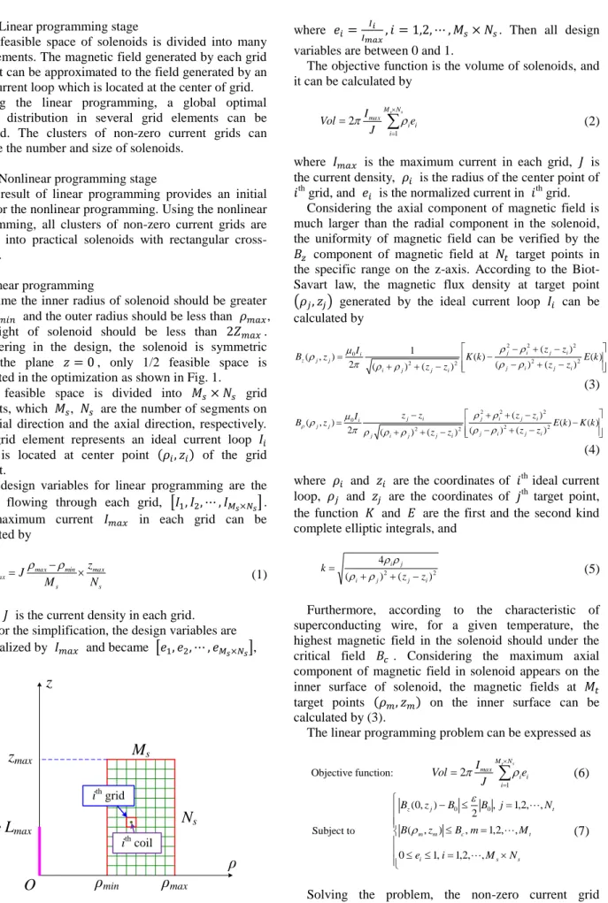
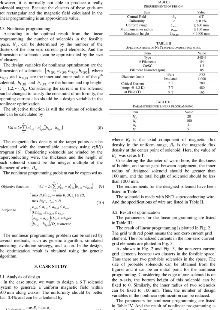
The result of linear programming is plotted in Fig. 2.
The grid with red point means the non-zero current grid element. The normalized currents in the non-zero current grid elements are plotted in Fig. 3.
As shown in Fig. 2 and Fig. 3, the non-zero current grid elements became two clusters in the feasible space.
Thus there are two probable solenoids in the space. The size of probable solenoids can be obtained from the figures and it can be an initial point for the nonlinear programming. Considering the edge of one solenoid is on the 𝜌-axis, the bottom height of this solenoid can be fixed to 0. Similarly, the inner radius of two solenoids can be fixed to 100 mm. Thus, the number of design variables in the nonlinear optimization can be reduced.
The parameters for nonlinear programming are listed in Table IV. And the result of nonlinear programming is plotted in Fig. 4. The magnetic flux density at the center
Item Value
Central Field 𝐵0 6 T
Uniformity 𝜀 ≤ 0.4%
Uniform range 𝐿𝑚𝑎𝑥 ≥ 600 mm
Minimum inner radius 𝜌𝑚𝑖𝑛 ≥ 100 mm
Maximum height 2𝑧𝑚𝑎𝑥 ≤ 1000 mm
Item Value
Type 54S43
# Filaments 54
Cu:SC 1.3
Filament Diameter (μm) 85
Diameter (mm) Bare 0.95
Insulated 1.000
Critical Current (Amps @ 4.2 K) at Field (T)
5 T 780
7 T 480
9 T 165
Item Value
𝑀𝑠 20
𝑁𝑠 100
𝑁𝑡 31
𝑀𝑡 51
Fig. 2. The optimization result of linear programming.
Fig. 3. The normalized current in each grid in the feasible space.
point is 5.9993 T, and the uniformity along the z-axis is less than 0.38% within 600 mm. At last, we can get the parameters of designed solenoids. The design result is listed in Table V.
TABLE IV
PARAMETERS FOR NONLINEAR OPTIMIZATION.
Item Value
𝑁𝑐 2
𝐷𝑤 1.000 mm
Fig. 4. The optimization result of nonlinear programming.
TABLE V
PARAMETERS OF DESIGNED SOLENOID.
Item Coil
1 2
𝑎1 (mm) 100 100
𝑎2 (mm) 142 150
𝑏1 (mm) 0 252.35
𝑏2 (mm) 246 463.35
Layers in radial direction 42 50
Layers in axial direction 246 211
Diameter of wire (mm) 1.000
Operating current (A) 116.02
Central field (T) 5.9993
Maximum field (T) 6.2589
Uniformity along z-axis 0.380%
Length of wire (km) 32.28
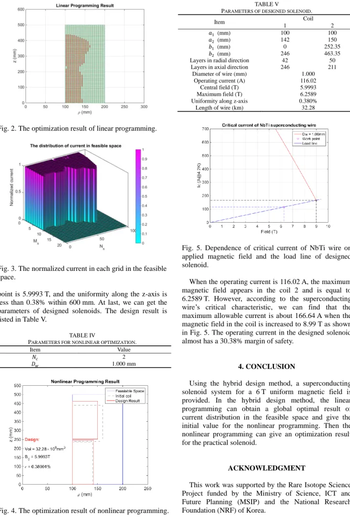
Fig. 5. Dependence of critical current of NbTi wire on applied magnetic field and the load line of designed solenoid.
When the operating current is 116.02 A, the maximum magnetic field appears in the coil 2 and is equal to 6.2589 T. However, according to the superconducting wire’s critical characteristic, we can find that the maximum allowable current is about 166.64 A when the magnetic field in the coil is increased to 8.99 T as shown in Fig. 5. The operating current in the designed solenoid almost has a 30.38% margin of safety.
4. CONCLUSION
Using the hybrid design method, a superconducting solenoid system for a 6 T uniform magnetic field is provided. In the hybrid design method, the linear programming can obtain a global optimal result of current distribution in the feasible space and give the initial value for the nonlinear programming. Then the nonlinear programming can give an optimization result for the practical solenoid.
ACKNOWLEDGMENT
This work was supported by the Rare Isotope Science Project funded by the Ministry of Science, ICT and Future Planning (MSIP) and the National Research Foundation (NRF) of Korea.
REFERENCES
[1] D. B. Montgomery, Solenoid Magnet Design, Wiley-Interscience a Division of John Wiley & Sons, New York, 1969.
[2] N. R. Shaw and R. E. Ansorge, “Genetic algorithm for MRI magnet design,” IEEE Transactions on Applied Superconductivity, vol. 12, no. 1, pp. 733-736, 2002.
[3] H. Xu, et al., “Homogeneous magnet design using linear programming,” IEEE Transactions on Magnetics, vol. 36, no. 2, pp. 476-483, 2000.
[4] S. Kondrashev, et al., “Development of electron beam ion source charge breeder for rare isotopes at Californium Rare Isotope Breeder Upgrade,” Rev. Sci. Instrum., vol. 83, pp. 02A902, 2012.
[5] Z. Ni, et al., “Globally optimal algorithm for design of 0.7 T actively shielded whole-body open MRI superconducting magnet system,” IEEE Transactions on Applied Superconductivity, vol. 23, no. 3, pp. 4401104, 2013.
[6] L. Huang and S. Lee, “A study on the effect of the condition number in the magnetic field mapping of the Air-Core solenoid,”
Progress in Superconductivity and Cryogenics, vol. 17, no. 2, pp.
31-35, 2015.